-
Featured Gallery Photo
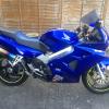
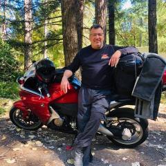
 CLASS at Infineon 2007

In 2007 I attended one of Reg Pridmore's CLASS days at Infineon and it was a blast. A sunny mid-May track day in NorCal is damn hard to beat.
photo used with permission, credit: Ian Donald - http://iandonald.com/
Copyright
© Ian Donald
All Activity
- Past hour
-
Certainly sounds like you set the cams correctly. But you can check by physically rotating the crank and observing the cams. If you start with #1 (left rear) with the intake cam bearing on the valve, then rotate the engine 450 degrees, #2 (front left) should now be pressing on the intake valve. If the cam timing is correct then maybe you have a VTEC problem? The VTEC actuation is around the 6800rpm mark.

- Today
-
Given your weird scenarios there had to be some strange wiring going on! Here's your original three abnormal issues. 1. Engine will not stop when I hit the kill switch - Not normal 2. Engine will not stop when switched off at the ignition - Not normal 3. Engine stops when I hit the kill switch AND turn the ignition off. 1. Finding a wire going from the switched Red/Black Ignition Switch wire to the Brown means the whole EFI is now powered by two sources. The ESR and the closed contacts of the FCR. Keeping the system and FCR in a power loop!. This explains situation 1. 2. Switching Ignition Off alone won't work because the added wire is getting a continuous feed back from the ESR closed contacts. 3. Equals a combination of 1 and 2! Both switches need to be off to break the power loop. Good luck, get that Fuel Pump wiring properly sorted. Keep us posted.
-
I am on my third set of Verge 011, really like the tires but only get 3000 miles on front and rear. Only ride backroads. While the center is still good the sides are gone.
-
Bank angle sensor location with pics 94 VFR 750?
Wald replied to racerreid's topic in Third and Fourth Generation VFR's
LOL! Took me a while to get it! -
 matmat joined the community
 -
I talked to my mechanic friend. There was no spark - because computer blocked the normal start sequence. When pushed, the computer omits those blockades apparently. This is how he explained this.
-
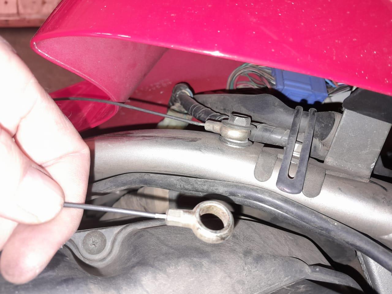
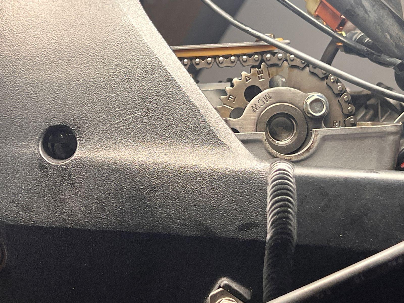
There's a hole in between the two bolts on the tank that it gets attached to with a screw/bolt.
-
I think one would need to call Barnett and place the order via telephone, since the website has a glitch.
-
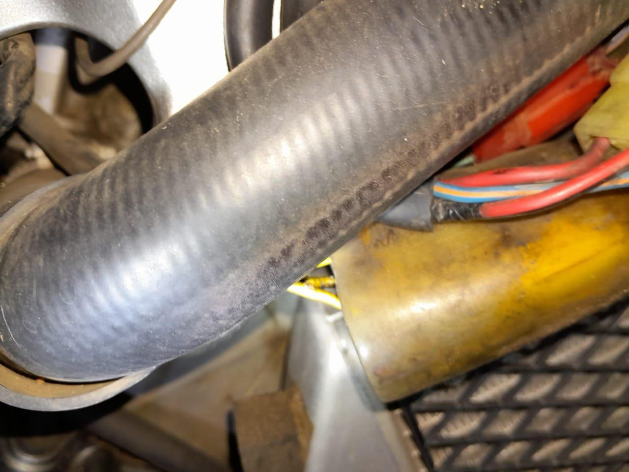
Time just doesn't seem on my side. At last got the a gap to get the right fairing off and immediate found non factory cabling. There is a wire running from my red&black ignition wire to the brown wire on the fuel pump. Looks like it was done long ago as the glue on the insulation tape has started to turns into dandruff. Hopefully I will get a gap to disconnect and see what happens this weekend, but I suspect it was a emergency repair to get power to the fuel ump and in the meanwhile the "broken" brown cable fixed itself and now the fuel ump is supplying power to the system after I switch of the ignition. I also found a cable that looks to be connected to something to stop it moving too far - at first thought it was supposed to attach the tank to the frame, but saw no missing/empty bolts. I have a karate competition Saturday, so again time away from the garage and Sunday morning has already been booked by the wife as well.
-
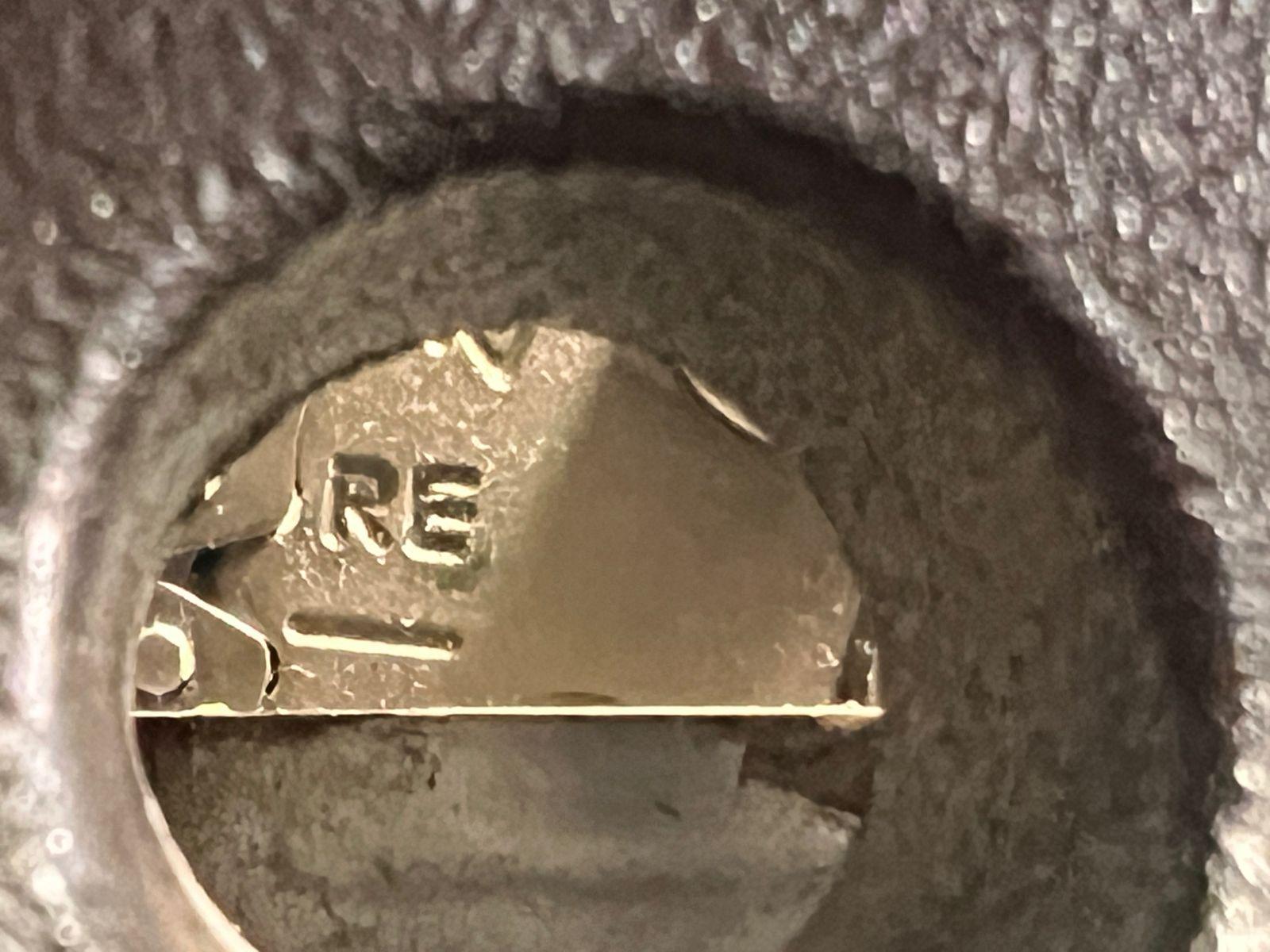
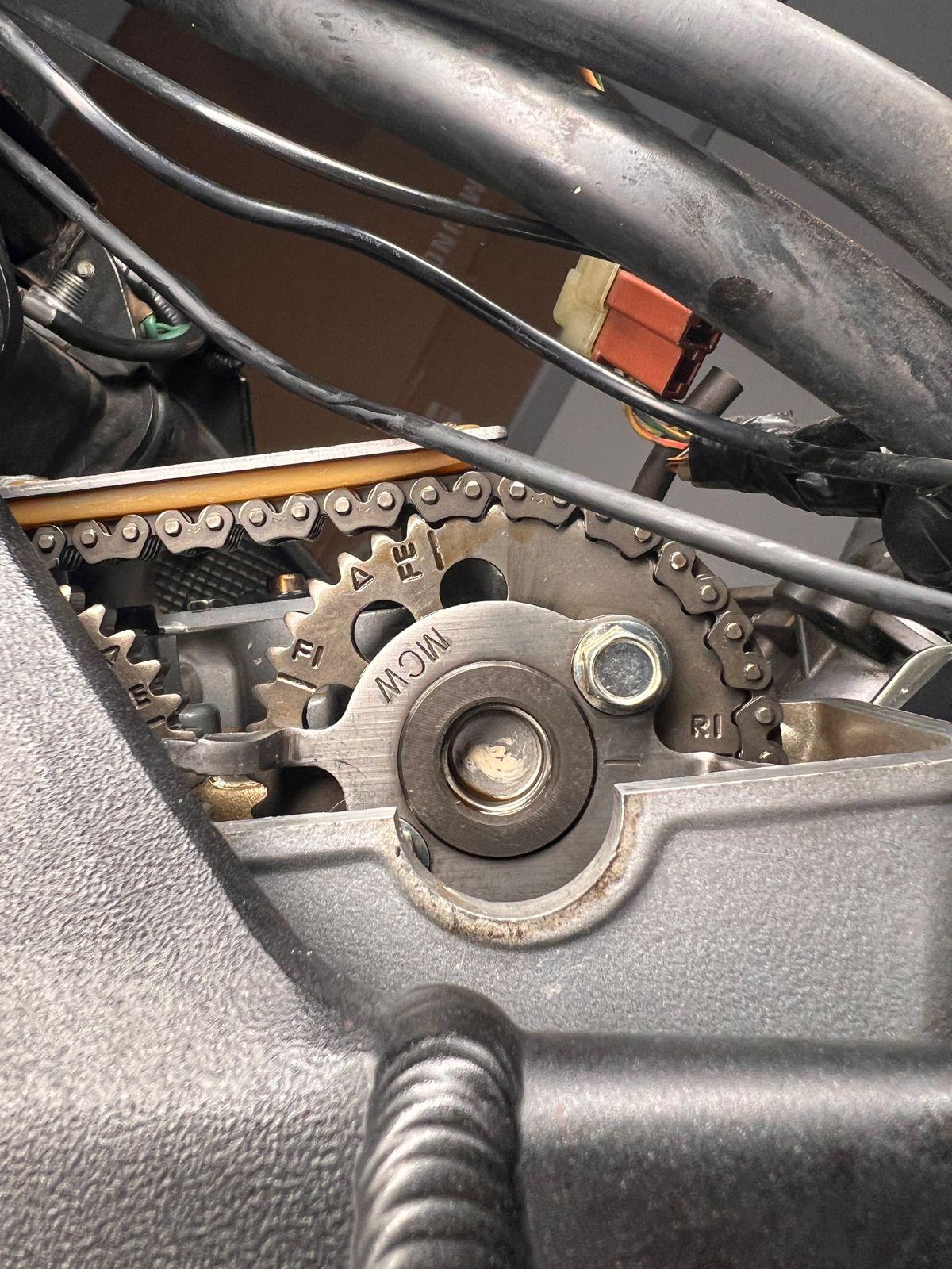
Just to visualise the position of the rear camshafts.
-
Yeah, right.
-
But you started it by push starting! If that was the case then push starting wouldn't work.
-
Yes, there was no spark. Maybe I'm wrong but It kinda does makes some sense to me... It looks like in this position of the cam shafts, the computer does not allow the bike to start by not sparking. That's the question. I think the computer is not initiating the start when cam shafts are in bad position = bad timing from the computer perspective? Not sure, we can check. We just replaced the battery so it's new. No, I asked if at every turn of the crankshaft the pistons are in the same position, but it was stupid question... As in the manual, when setting the timing, you set the crankshaft to 3T, set the rear, move the crankshaft clockwise by 450 degrees and set the front. It's hard to mess up... But something is wrong anyways.
-
Bit of a side issue, but reviewing your old post you had a No Spark situation. Now what got the bike going was to push start it! Have you confirmed again that when cranking you don't have a spark? This is not making sense unless the battery is bad, or some form of voltage drop on the EFI 12v Supply wire being the Black/White wire while cranking. If the voltage on this wire drops badly while cranking it could effectively disable the ECM = No Spark. If you had a spark issue, how could changing cam chains have any effect of having a spark or not? What does the battery voltage drop to while cranking? Did you ever get to replace the battery? And with engine running have you measured your charging voltage? Camshaft rotates at half the crankshaft. So 360deg of crankshaft movement will mean the camshaft has moved 180deg. Which would mean your cam index marks would be pointing inwards instead of outwards. Someone else might confirm this! Guess your asking what would happen if the cams were set correctly but at TDC of exhaust stroke? That could be interesting, not sure of the outcome! Think you may end up with closed valves while the crank is in the induction stroke.
-
Hi Terry, I have an idea... What would happen if after removing the cam chains, the crankshaft would be rotated 360 degrees and then set as in the manual? Would it start? How would it behave? Any idea?
-
Hey Terry. Over to you, are you able to confirm his crank to cam alignments, I'm out of my comfort zone as Cams and Cranks don't have elektrikery going through them!
-
Grum might be onto something here. I know with the VTR1000F engine, it was possible to set the cams in the front and rear heads correctly with respect to the crank/marks, but out of time between the front and rear heads. This meant that instead of the rear cylinder firing 270 degrees after the front, the rear missed another 360 rotation and so fired at 630 degrees. In that engine it started and ran fine but was reluctant to rev. The manual has some very specific instructions about the sequence of cam reinstallation so that this is accounted for. I'm not saying this is the issue for you but it won't be hard to check.
-
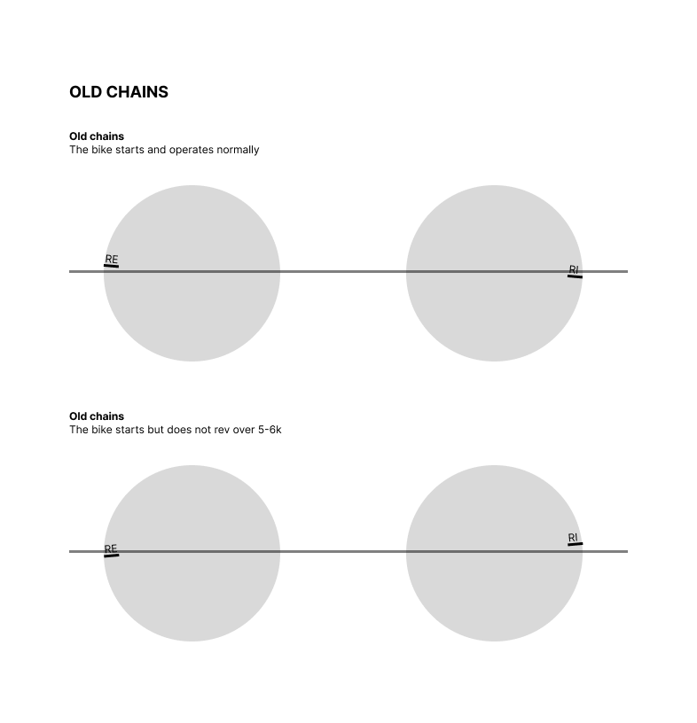
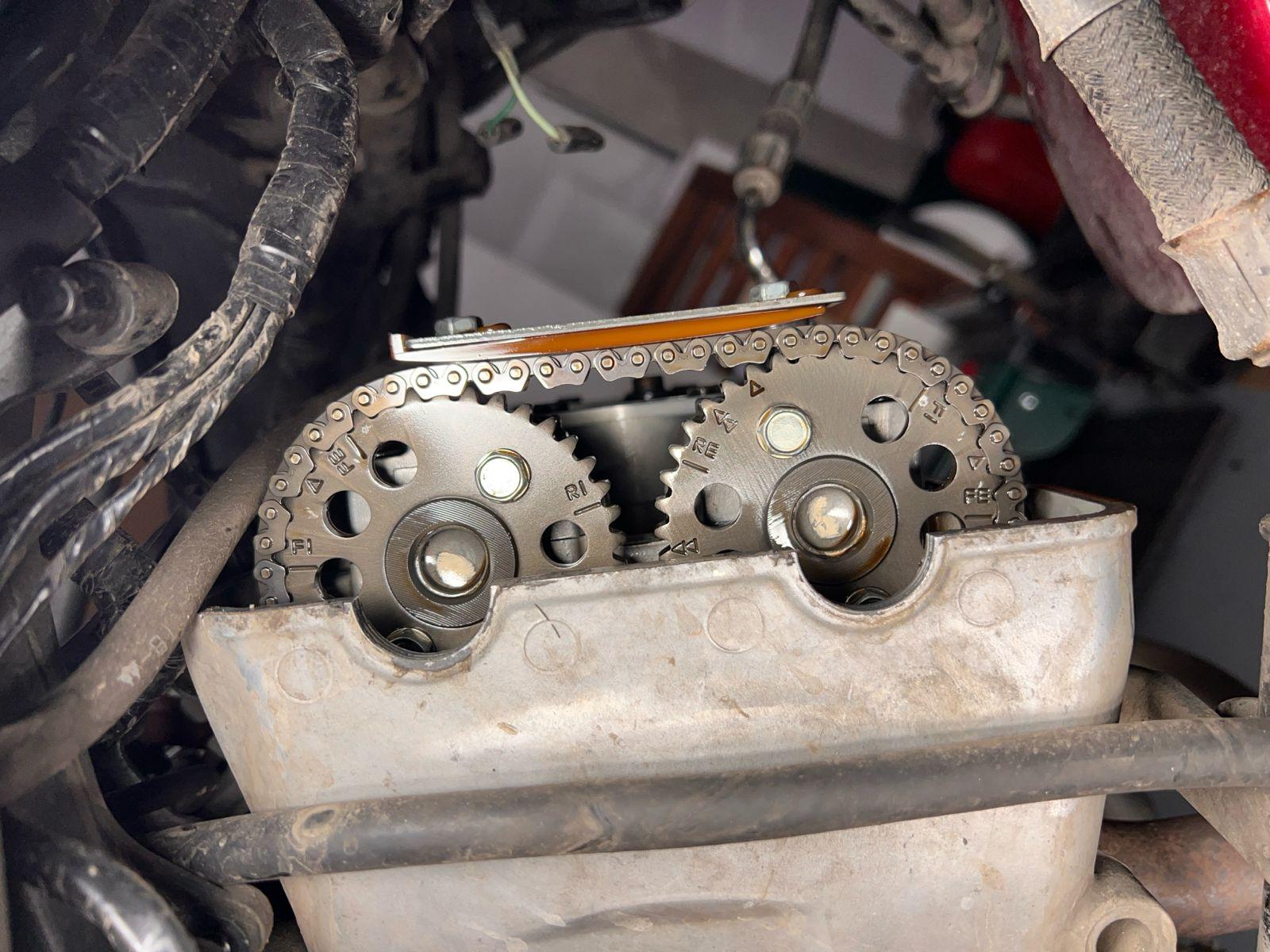
No, the crankshaft was in the correct positions 3T/4T during replacement and was not moved... The only thing that affects this position is chains. The old chains are slightly more loose, the new ones are bit more tight. On the old chains (the bike starting and working properly) On the new chains (the bike starts, but does not rev over 5k): WhatsApp Video 2024-04-19 at 08.56.56.mp4 When we move the cam shafts slightly forward, then the bike does not start but when push-started, revs over 5k... Loosing my mind here... 🙈
-
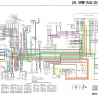
Have you possibly slightly upset the alignment between crankshaft and camshaft? Was the crankshaft 4T mark aligned with the index mark Before determining the Cams weren't positioned correctly? Did you disturb the crankshaft position while trying to fit new chains and aligning the Cam indexes? Might be worth rechecking this being sure that firstly the crankshaft 4T index is set correctly, or has this already been thoroughly checked? Attached is info from 5gen Service Manual, Technical Features section.
-
Do you run the vfrd headers with 2 bungs in the collectors? What protrusion? RapidBike right?
-

Replace VTEC lifters with normal lifters
Renan replied to Renan's question in Modification Questions
Thanks guys, I think I got enough information now. -
Based on what I have seen from the leds on the controller and the fact that it is showing afr values after 30 sec I suspect you are right on this. Many aftermarket LSU controllers use their own algorithm and hardware. The BOSCH controller are Superior afaik. If i blow another set I will try a timer as well. I tried getting answers to the heat procedure but they gave me a pretty standard answer with no specifics.
-
Hi @Grum, thank you for the quick answer. The valves adjustment was just done so they are all in spec. I'm not sure about the other things... Because the behaviour depends purely on the position of the cam shafts. If they're aligned correctly, by the book - the bike starts but does not rev over 5k - which indicates wrong timing. When the position is adjusted by one sprocket tooth forward, as on the old chains (when the bike was starting and operating fully) the bike does not start by itself but when push-started, it revs fully indicating the correct timing... Indicating the problem with start sequence Is it possible that the computer somehow "learns" the position of the cam shafts vs crankshaft?
-

Replace VTEC lifters with normal lifters
gropula replied to Renan's question in Modification Questions
What's the difference? This achieves your desired goal in a simple way. Your way can't work without an unknown amount of machining and/or mixing and matching parts. There's no place for a shim as it's usually a part of the VTEC bucket. The retainer sits very low. Experimenting with valve clearance trough lapping could achieve desired clearance but further adjustment as the valve recedes into the seat would be more complicated than the usual way of replacing the bucket with a thinner one, thus totally defeating the purpose of having a simpler adjustment procedure. If you want 4 valves all the time and easier clearance measurment follow the thread mohawk posted. Adjustment will be the same - replace the VTEC bucket. Yes it's more expensive than shimming but a 100$ for three buckets every 5 years is better than reinventing the valvetrain. -
You don't have to buy the sensor from Rapidbike. It's an of the shelf part with Bosch part number 0 258 017 025, 5 wire sensor. It is used in some OEM applications, BMW I think. When I killed it I replaced it with a part number 0 281 004 157, 5 wire sensor from my Peugeot car which has the o2 sensor disabled in ECU so it didn't mind. Worked well before it died. I guess any 5 wire bosch 4.9 sensor with appropriate connector will work. The only difference I can see is the length of the wire and some heat shielding that may or may not be present on the sensor wiring. I killed the second one as well so I will wire in a timed relay which will wait for a set amount of time, say 5 minutes, before it gives 12V to the wideband. This way the exhaust will have time to heat up and any water condensation will evaporate before the sensor starts heating up. I found the timed relay on aliexpress for a few bucks and I'll install it under the seat. I'll buy another Bosch 4.9 wideband that has the same connector and 5 wires but a different part number. I think the rapid bike wideband controller has a bad heating strategy. It heats up too soon so when a droplet of condensation hits the sensor it dies.
-

Replace VTEC lifters with normal lifters
Presson replied to Renan's question in Modification Questions
Your idea has been discussed before. It doesn't seem like anyone has done the deep dive along the lines you propose. From the look of the parts diagram it appears you would need to change the VTEC valves for standard ones together with springs, collets etc. Lap in the new valves, experiment with valve clearances and possibly remap the ECU parameters. I doubt it would be straightforward.


.jpeg.cf54f219f587e933a73443b8dbc884c8.jpeg)
.jpeg.194b93ea49e01fa3d94432d8460c9e03.jpeg)


-
VFRD Mission Statement
For owners of the Honda Interceptor and related Honda V4 motorcycles, for the purpose of mutual help concerning safe riding, maintenance, and performance of their motorcycles.
Contributions - VFRD is a member supported website with no commercial advertising

-
Forum Statistics
-
Total Topics25.6k
-
Total Posts355.3k
-
-
Who's Online (See full list)
-
Member Statistics
-
Upcoming Events
-
Latest Classifieds
-
-
Top Downloads
-
-
Popular Contributors
-
Blog Statistics
-
Total Blogs116
-
Total Entries345
-
-
Gallery Statistics
-
Blog Entries
-
-
Blog Comments
-

-
By interceptor69 · Posted
Oops. I do believe I know how to post YT videos or they wouldn't be on YT. However I may have screwed up copying the link to the playlist. Thanks for the helpful comment. -
 I think that you might not know how to post videos. You're in your YT studio in these links. You need the link to the actual video.
 -
-
-
-
Most Contributions
-