MadScientist
-
Posts
642 -
Joined
-
Last visited
-
Days Won
6


MadScientist's Achievements
")


-
Absolutely the same reasons I change my own tires. For anyone else using the Harbor Freight changer, check out mojoblocks. I also have the mojolever. Good tools, if a bit expensive. Can't recommend them enough. Not sure what he uses, but I've been using a Marc Parnes balancer for years. I had the balance checked the first couple times and they were inconsequentially close. Takes a bit of time to check, add weights, then check again, but at least I know it is done right. I've made a set of "weights" that I tape on to do the balancing, then remove and stick the "permanent" weights on.
-

What did you do to your VFR Today?
MadScientist replied to weee06's topic in Eighth Generation VFR's
Just out of curiosity, was the wire soldered (either tinned or to the connector)? -
Not sure overall how motorcycle prices in Washington compare to Wisconsin, but my local dealer has a a new red 2015 deluxe for $6987 + ttl. No delivery/setup. I wouldn't call $8700 a good deal. Brand new 2014 non-deluxe under $6k.
-
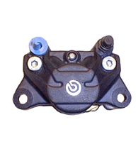
Any reason not to use a caliper with the side bleed and banjo? Like this: If it matters, I'm running 83 degree Bridgeport valve stems.

-
Yeah, so sounds like you know the problem and you want someone to tell you how to rig it up in a potentially improper manner. If one of those relays overheats and fuses "closed" or the wiring is not done properly, I'm not going to be the one responsible for burning your bike to the ground or killing you/others. Even if I say "do this at your own risk", it does not necessarily absolve me of responsibility. This may sound harsh, but you will get plenty of advice here how to do it the right way. I wouldn't, not would I recommend that you ride your bike on public roads in it's current condition - what if you have an accident and emergency personnel can't turn off your bike. The only thing I will say is that the usual current draw for a relay is about 160mA. One of your relays is probably connected to a circuit not controlled by the key or kill switch since this is in the neighborhood of your current draw.
-
I've also heard of people mounting a magnet into the heel of riding boots for this reason. Sounds like an idea for a product right there, maybe a velcro-on magnet strap. Would have to find a way to do it without interfering with the grip of the footwear on the pegs or ground though. This is hearsay, of course. I don't know if even a small, high powered magnet is capable of tripping the sensor loops.
-
Brake question. Can someone try it for me please?
MadScientist replied to SportTouringCZ's topic in Fifth Generation VFR's
The rear middle piston is not controlled by either brake lever. There is a master cylinder in the mounting bracket of the left side brake caliper - bleeding instructions can be found for this circuit starting on page 15-11 in the manual. You will have to squeeze the brake caliper mount toward the fork tubes to pressurize this circuit. -
07 R1 Racecar Project Cranks but Won't Start
MadScientist replied to paulmeisterpk's topic in OTHER Motorcycle Talk (non vfr)
Unfortunately not, the panel is required because they are actually printed out on an LCD display rather than light flashes. Shame about the dash, unfortunately they are damn expensive on ebay too. If the wires and connectors are gone, it might be more work and money than the time it might save to re-wire the OEM dash. I see an immobilizer on the schematic also. Do you still have it wired in or did you figure out a bypass? My other possible suspects are wiring (as always) and 12. Starting circuit cut-off relay. Can you do me a favor and check the voltage at any ignition coil from red/black to chassis ground and at any injector from Red/Violet(?) to ground with the key on (no cranking)? -
New 5th/6th/8th gen performance header now in production in USA
MadScientist replied to sfdownhill's topic in Exhaust Systems
PCV requires an ignition module. Not sure if it is even compatible with the VFR800 PCV either - doesn't show up as an additional purchase option. -
07 R1 Racecar Project Cranks but Won't Start
MadScientist replied to paulmeisterpk's topic in OTHER Motorcycle Talk (non vfr)
Do you have the R1 dashboard? If so, check if there are any error codes: https://www.youtube.com/watch?v=z1mNYU0Zr2M Report back if you do. Seems other people have no problems starting their R1s with broken fan or headlight relays; at least individually, they don't appear to be required for startup. That said, the ECU provides ground signal to energize both of these relays. You could check the cam and crank position sensors for proper function with an oscilloscope; you won't get any truly meaningful information with a regular multi meter. -
New 5th/6th/8th gen performance header now in production in USA
MadScientist replied to sfdownhill's topic in Exhaust Systems
Yeah, I was concerned about this too when I saw it. I think it will be ok, but I can't say for sure. Some of the pictures look worse than others, but the one looking forward from the rear tire edge (picture 5) is reassuring. The lower O2 sensor appears to be above the pipe midline and at a slight downward angle toward the tip, even on the sidestand. It is close either way, that's for sure. Standing upright, it looks like there should be no issues. Just have to be careful with left lean until the exhaust is warmed up. Also, don't fill the exhaust with water when washing... -
New 5th/6th/8th gen performance header now in production in USA
MadScientist replied to sfdownhill's topic in Exhaust Systems
They are most likely 180 degree cranks like the VFR, NC13-NC24 had 180 degree cranks, NC30 & 35 had 360 degree (like the RC30/45 and early VFxxxF). Of course they could have later motor swaps or crank/cam swaps. IDK if the earlier engines are compatible with the later parts though. -
A small tip on the loudness - I find that the baffles are a little too quiet, but open is too loud. I usually cut down and drill holes in the baffle insert until I get the volume level where I like it - cut/drill a little at a time and test until you find the volume level that you like. I don't have a Delkevic, but this has worked out on a bunch of other brands so there shouldn't be any difference.
-
New 5th/6th/8th gen performance header now in production in USA
MadScientist replied to sfdownhill's topic in Exhaust Systems
Whoops, I just sent you and Lance a PM in case I missed something. Should have checked here first. I still can't believe this is actually happening. Thanks for all your hard work! -
Vibrations (possible spark plugs)
MadScientist replied to SweViffer's topic in Sixth Generation VFR's
The traces of fine white dust are almost definitely old dried up dielectric grease.