Mohawk
-
Posts
2,132 -
Joined
-
Last visited
-
Days Won
54
Content Type
Forums
Profiles
Gallery
Blogs
Downloads
Events
Everything posted by Mohawk
-
The simple answer here would be to fit 2-stoke reed valve blocks into the plenum, thus if at any point the plenum chamber is at less than atmospheric pressure then they will open & allow air in !
-
Vtec has a narrower valve included angle.
-
You are s braver man than me to even consider that desth trap in motion 😂
-
In the V
-
I just found the wax unit on my Y2K model was fine if allowed to warm up before riding, but if I set off with it on, it would get too hot to soon & disengage, then when you slowed for a junction the bike would die as still to cold and fast idle was already off. Much better now with manual fast idle lever, wait until display says 60C then turn it off 👍
-
So I did a load of digging into this when I did mine. 4 hole from many car tests are much better than single hole, but 12 hole is more the norm, but the step up is not the same as 1-4 when compared with 4-12 but 1-12 is better. Some newer injectors are 16 hole. CBR600F4 & CBR929 injectors are the same 4 hole units with the same connector as 5th gen, just use the 5th gen mounting washers & remove the plastic orientation stub, which 5th gen does not have. But are designed for higher pressure. I tried with VFR regulator & had to add loads of fuel. I then tried 4bar, but was to much. So switched to 3bar & its great. I run 14.2 AFR on my RBR + MTB, runs clean, better MPG & no over heating even in silly 33c temps. The early Hayabusa used the same injectors as the 5th gen. You can buy fairly expensive Hayabusa aftermarket units, 12-16 hole. The simplest upgrade is a 6th gen throttle body, plus airbox, bottom half will do, as tops are the same. Just switch the TB harness at the large multi block that you tap for PC3/V or RBR etc. I can't guarantee the pinout is the same so consult a wiring diagram first. 2014+ 8th model looks the same as 6th gen, but I've never compared them in the flesh. YMMV A few people on here with 6th gens with 5th engines installed have reported better mpg with PC or RBR installed. The one advantage of the single hole pintle injector is that its effectively self cleaning & very hard to gum up. The tiny multi hole units are much easier to block. Hope that helps.
-
Why not just add additional bikes to your existing policy ? Got 3 bikes on mine, doesn't cost much more & they work on the principle that you can only ride one at a time.
-
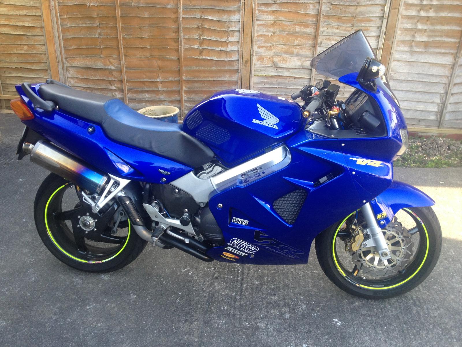
No pics of my early days, but in 1980 first bike was a Honda C90, then;- Honda CB100N Kawasaki Z200 Honda CB400N, died in a crash that crushed a knuckle on my left foot. Yamaha RD250LC, sold to pay for ski trip with love of my life. Where is she now, was a bad decision. Next should have been RD350YPVS, but got written off 2 days before I would have got it😩 Honda XBR500, nearly ripped arm off in bad crash. Honda CBX550F2, crashed into parked car to avoid being crushed by an 18 wheeler. Honda VF500F2 Honda CBR600F4 (FY in UK) Honda ANF125 as a winter bike, The Chicken Chaser. Honda CBF250F first one in UK of the MK2 model. Suzuki DRZ400SM was a blast Kawasaki ZZR250 x2 built next winter bike, now refurbed & modified, too good for winter now. Working on converting to 315cc with Ninja 300 engine. Honda VFR800Fi the one 👍 You all know my baby Kawasaki Versys-X 300, the new SUV of the bike world. Bought as winter bike & used for light off roading, fell off & knackered same arm again, 32 years later😩 Fancy a Guzzi V85TT as an all round universal bike.
-
I think its more 😂
-
Kids are not eligible for Darwin awards, but it appears some adults are so qualified for one they volunteer their kids to join them. I do wonder at the average intelligence of humanity 😩
-
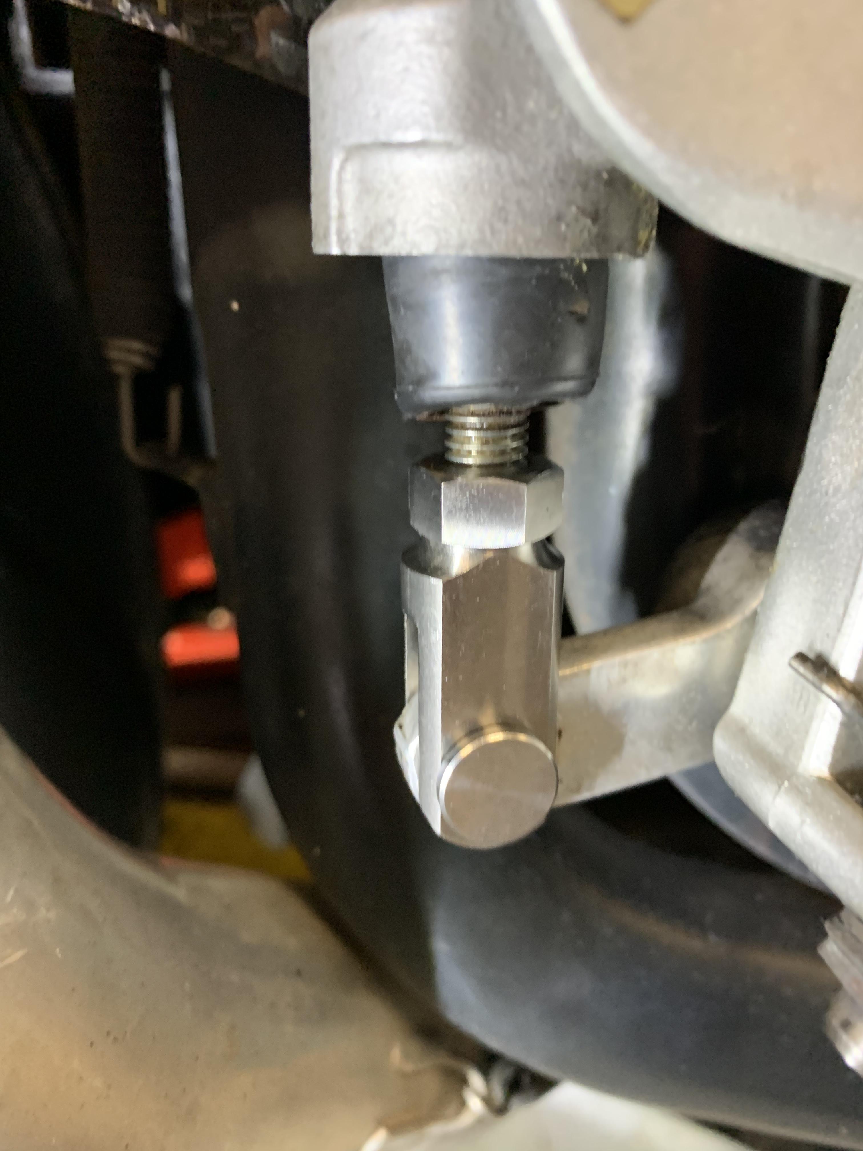
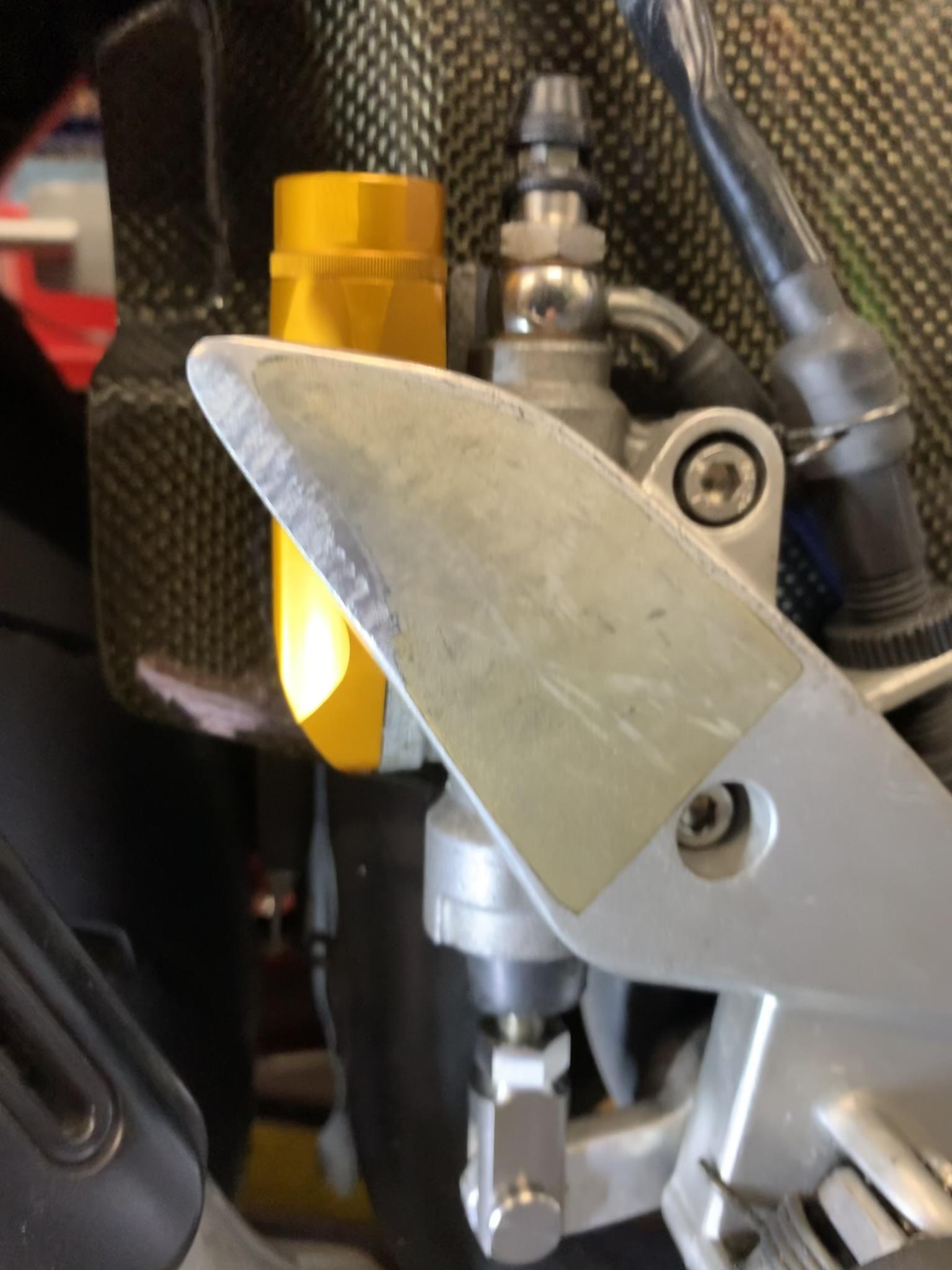
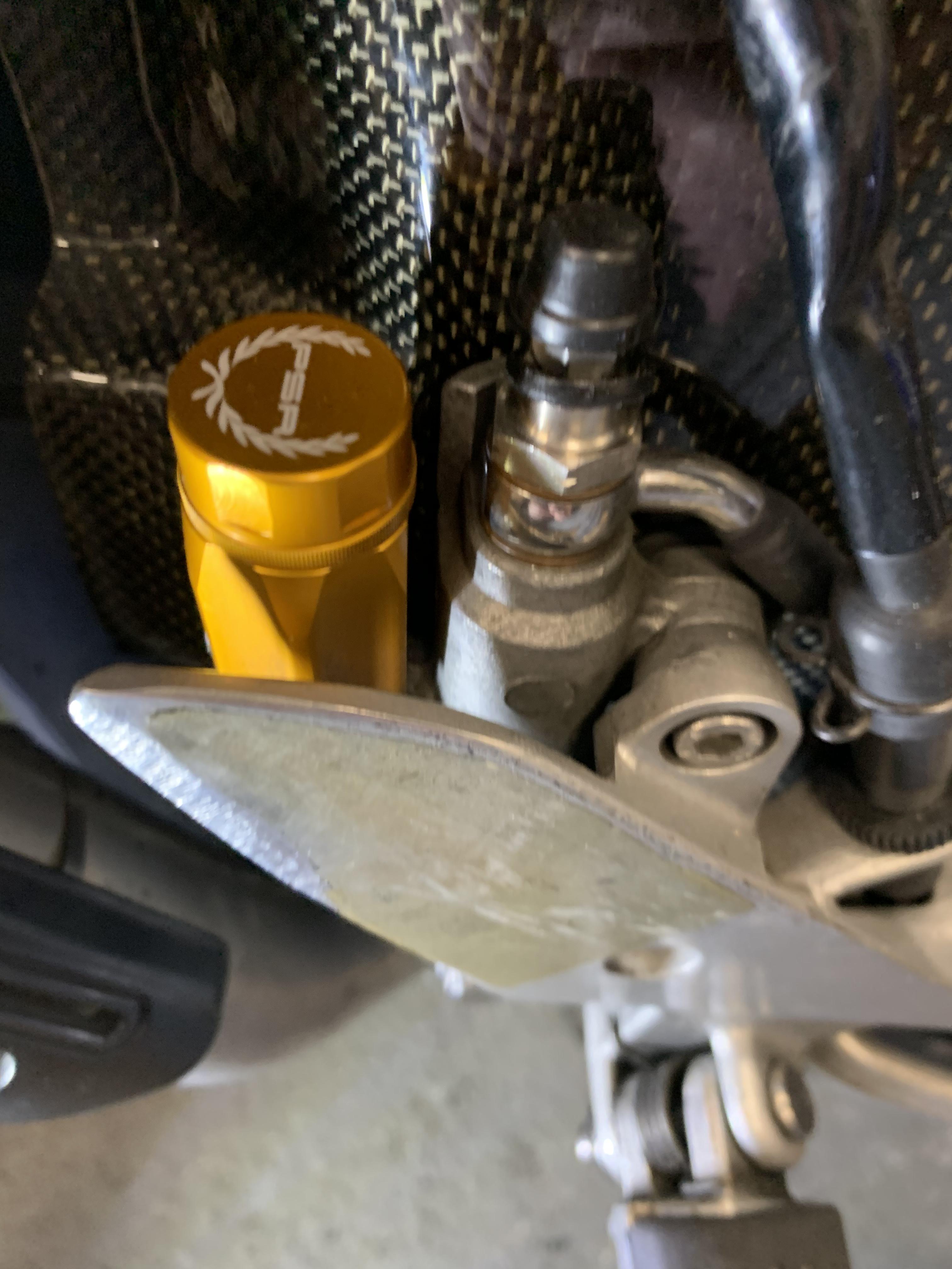
Fitted a nice Ti Rear brake lever clevis with Ti pin an nut. Saved 20grams & goes well with my PSR M/C Reservoir 👍

-
VF500F2 Aka MBD Incubation Period At Least 52 Years
Mohawk replied to Dutchy's topic in Earlier VFRs
That Looks ready to roll, enjoy 👍 -
VF500F2 Aka MBD Incubation Period At Least 52 Years
Mohawk replied to Dutchy's topic in Earlier VFRs
Alternately get those blasted & ceracoted 👍 -
VF500F2 Aka MBD Incubation Period At Least 52 Years
Mohawk replied to Dutchy's topic in Earlier VFRs
If you need a replacement system then predator exhausts in the UK do a single silencer full stainless system. I had one on my 86 model. Made 59HP on the dyno with 56K/miles on the clock 👍 -
I can't see any wear in those pics. The apparent gap looks to be wrong but does not show wear. May be a moulding error. The brake pad should not move front to rear, only up/down inline with the disc rotation direction. If it moved as per the supposed wear then the pad would be contacting the disc bobbins & you would have wear on the disc all the way to its inner diameter. Show a pic of the inside of the right disc.
-
Hi Mohawk, Thank you for your donation of --. We look forward to improving the forums with your donation. Thanks VFRDiscussion
-
- 1
-

-
Quick Poll: Are you using Chain Lube or Chain Paste?
Mohawk replied to VFR80025th's topic in Eighth Generation VFR's
SAE 90 gear oil 👍 -
Not worth it on 5th Gen. I fitted the RBR with the intention of using it. With 98Ron fuel, it will only take a maximum of 3 degrees before pre-ignition, with 95Ron only 2 degrees. And all of that below 6Krpm. Honda took the timing from the RC45 at the end of its production & they had it pretty much spot on.
-
UK gov has changed annual vehicle tax rates 2 years ago for the same reason. Were low emission petrol cars were free, they are now £155pa ($205), only zero emission vehicles are free now. They just dropped the EV grant from £2500 to £1500 the other day. And hilariously reduced the minimum vehicle price from £35K to £32K, I'd love to know what universe they are living in. If you can afford a £35K car you don't need a grant. And if you look at the history of gov grants here, what cost £20K yesterday & then a £5K grant was introduced, then tomorrow it cost £25K 🤔 Never mind buy fuel & enjoy the ride until ya can't no more. UK has sales of approx 47BIllion Litres of petrol/diesel per year. Or 258Million (UK) 40gallon drums. The chart 1.3 on page 3 here shows how much transport consumes Last time I checked (a few years ago) 93% of oil production was used for transport. And 97% of transport was liquid fuelled. The chart 1.3 showing everything above transport is basically gas & electrical consumption. To replace all that liquid fuelled transport would require a doubling of UK electrical generation capacity & we are struggling to keep the lights on now. 😩 Oh and we want to reduce emissions 😗
-
EV's are not expensive to charge, much cheaper than liquid fuels. The link here says approx £16 for 280mile range https://docs.google.com/spreadsheets/d/1k76UKn1ZwqpTzoav7QbglgaiaZBkvhywOWqc88dWJHU/htmlview So for the same range my diesel car costs more than twice that, based on UK fuel costs (which are extortionate). But the car cost just over half what a Tesla would. That's a lot of litres ! The problem is there is NOT enough electrical generating capacity in any country to allow conversion of the whole ICE fleet to electric. And currently most public charge points only support 4-10 vehicles, so of they are all full when you arrive you may have to wait an hour BEFORE you start charging. How do you plan that into your trip ? Battery swapping is an answer, much better than sh!t cheap chargers especially in USA based electric networks where 110v is often less than the battery voltages, thus requiring step up transformers to increase voltage which reduces amps available to charge the battery at home. And reduces charging efficiency.
-
Gel seats are a gimmick IMHO, they do not address the major seat comfort issues, which are usually the seat is to Soft (unsupportive) or to Hard causes pressure points. Gel does not really address either & they are not permeable so cause your butt to sweat. Soft is usually because the foam or its coating are too soft & don't provide support. I fitted a leather seat cover to my 5th gen over the top of the vinyl to avoid water ingress into the seat foam. This improved the weight distribution across the seat & has been great since. My Versys-X 300 is on its 5th seat & still not great. I tried a gel insert, but was no better than the stock seat which is atrocious. Every butt is different, what works for one will be a pain for another. FYI I'm 6'1" 15.5st with a 34" leg.
-
Picking new cylinder wall material need help
Mohawk replied to Vfr800witdawaffle's topic in Eighth Generation VFR's
Without some serious $ this would never fly. Using the CBR rod would mean the piston would reach TDC 3mm below deck height adding over 15cc to the VFR combustion chamber volume, which would reduce CR to approx 8.25/1. So a longer rod would be required. I didn't even factor in the additional head gasket volume from the larger bore. From my calculations the stock combustion chamber volume including the head gasket volume is 18.42cc (swept volume + head volume / head volume) Stock CR is 11.6/1. -
Nah its great I suggested it many years before it was allowed. But I wanted the teams to have variable aero, not an overtaking aid controlled by race control. F1 has run its course nothing new coming out of it from 20years. And the leaving director, just announced that they can't go all electric until after 2050 because they gave that guarantee to Formula-E !
-
So just had a look at battery life for LifePO4 batteries. Based on a perfect charging routine & 75% average discharge. You should get between 4-8K charge cycles, dependant on battery temperature. So if that holds true & your battery has 150mile range to 75% discharge state. Then driven that far every day for 10years the battery should be good for over 500K/miles. So battery longevity should not be a concern, as that is 50-66% more miles than most ICE vehicles cover. The real problem is the charging infrastructure required to replace the fleet. If I meet another EV geek that says "my Tesla can get 80% in 20minutes on a fast charger" I'll enlighten them that I can get my ICE car from 0-100% in less than 5 minutes & it cost HALF what your Tesla does & goes twice as far on a full tank. When you next pull off to charge & find the few charge points occupied, how will that hour wait feel ? 😩
-
I think you will find a combination of factors coming together over time. Like the current surge in secondhand prices due to the lack of sales of new vehicles over the last 2 years to back fill the losses from scrapped vehicles. Prices for secondhand ICE bikes will increase once the sale of new ones is banned. They will stay in demand for as long as fuel is available at reasonable cost. This explains the proposed bans on modifying your own property. By killing the aftermarket then keeping ICE bikes running will become much harder. Personally I'm convinced the whole global warming scam is political cover for peak oil. If they told the public oil was running out there would be panic, so saving the planet makes them feel good. The only way to increase economic activity if killing off oil, is to stage its replacement. Agreed a load of companies are lined up to fleece you. When electric cars are cheaper to make than ICE, why are they LOTS more expensive ? Hmmmm ? Just call be an old conspiracist but the whole thing smells of the Bildeburger's Global plan to keep themselves rich. The world will soon return to surfdom.