Leaderboard


Popular Content
Showing content with the highest reputation on 06/19/2022 in all areas
-
1 point
-
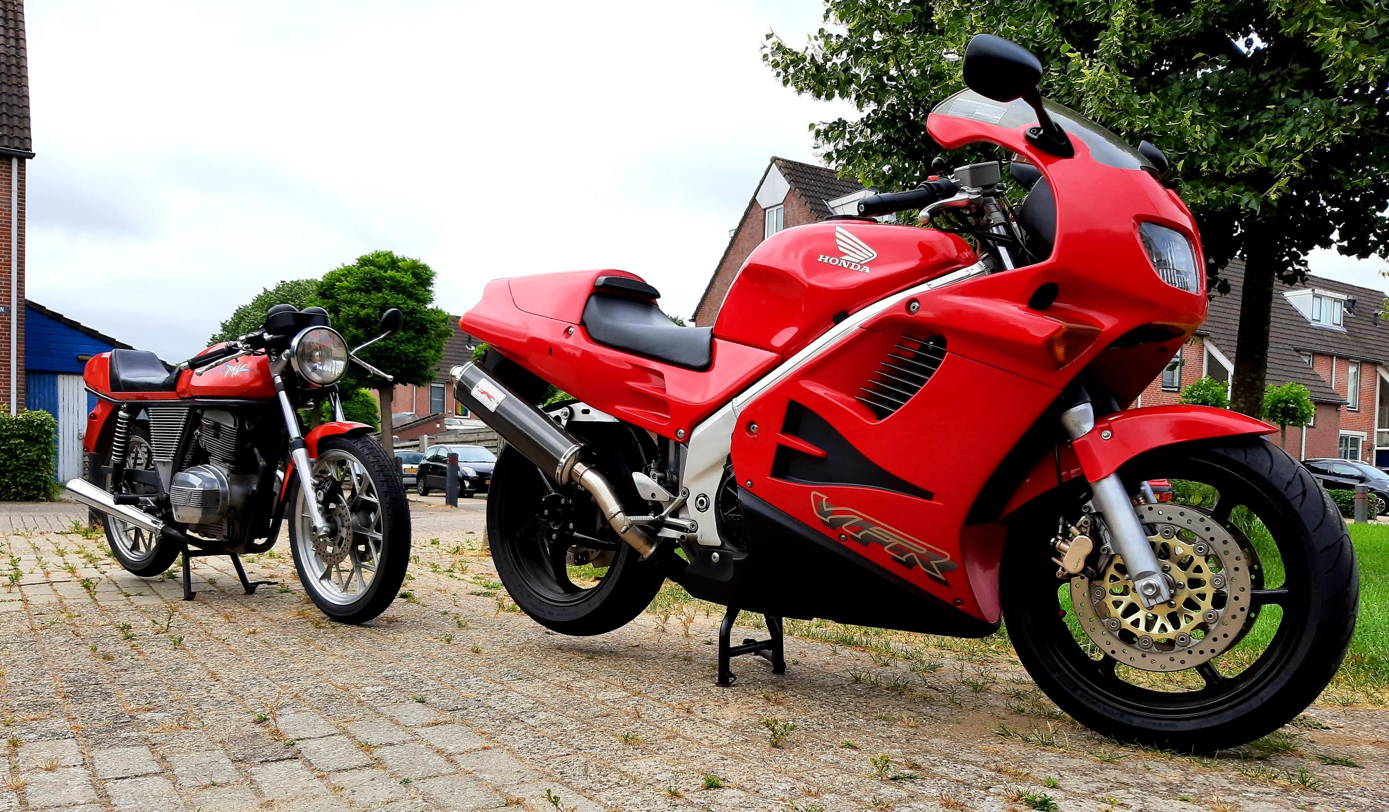
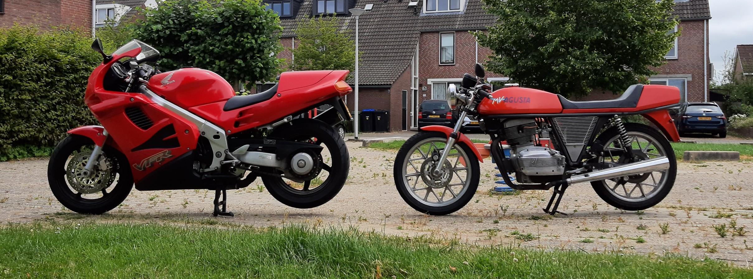
Redheads Galore
 1 point
 -
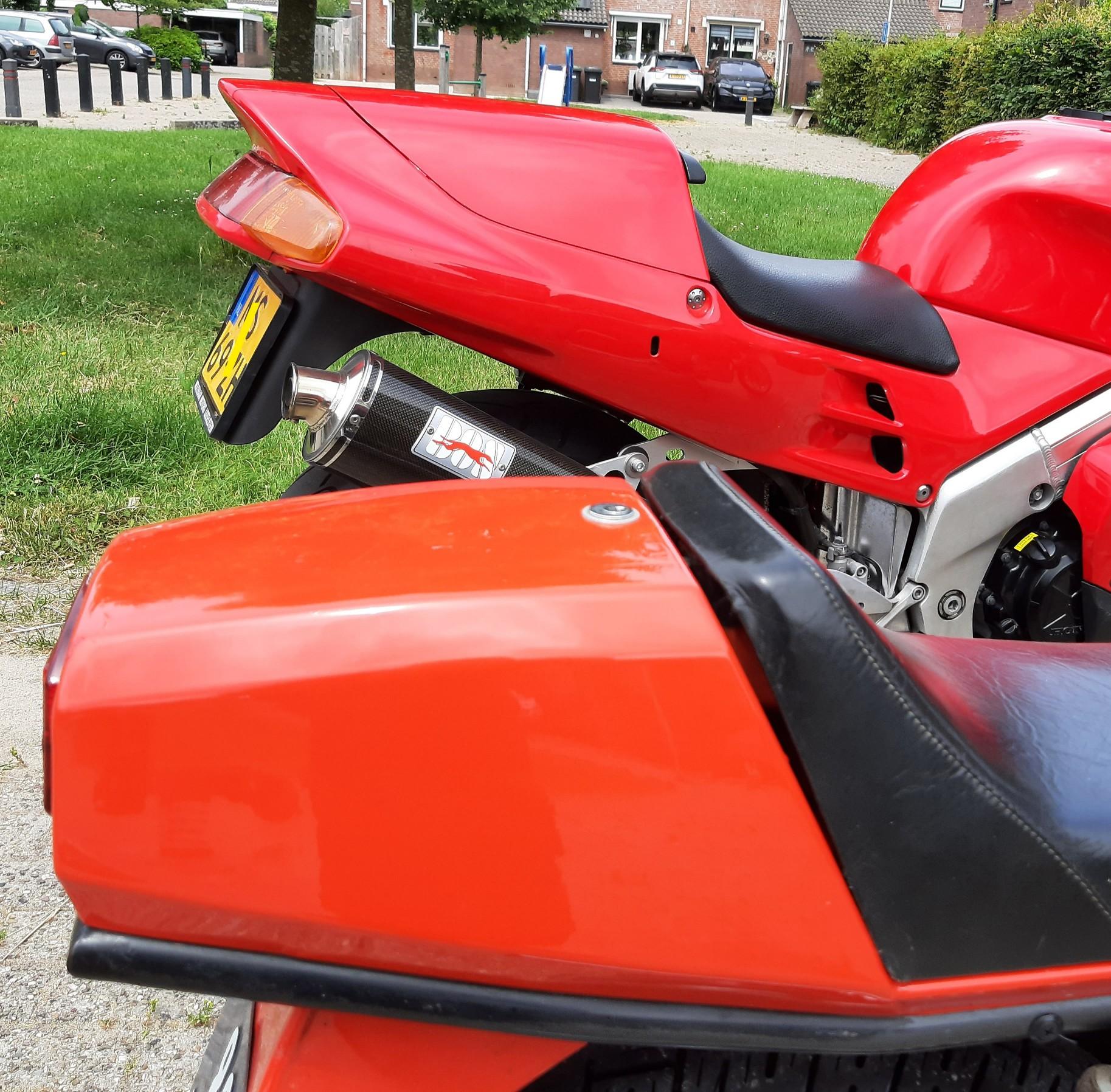
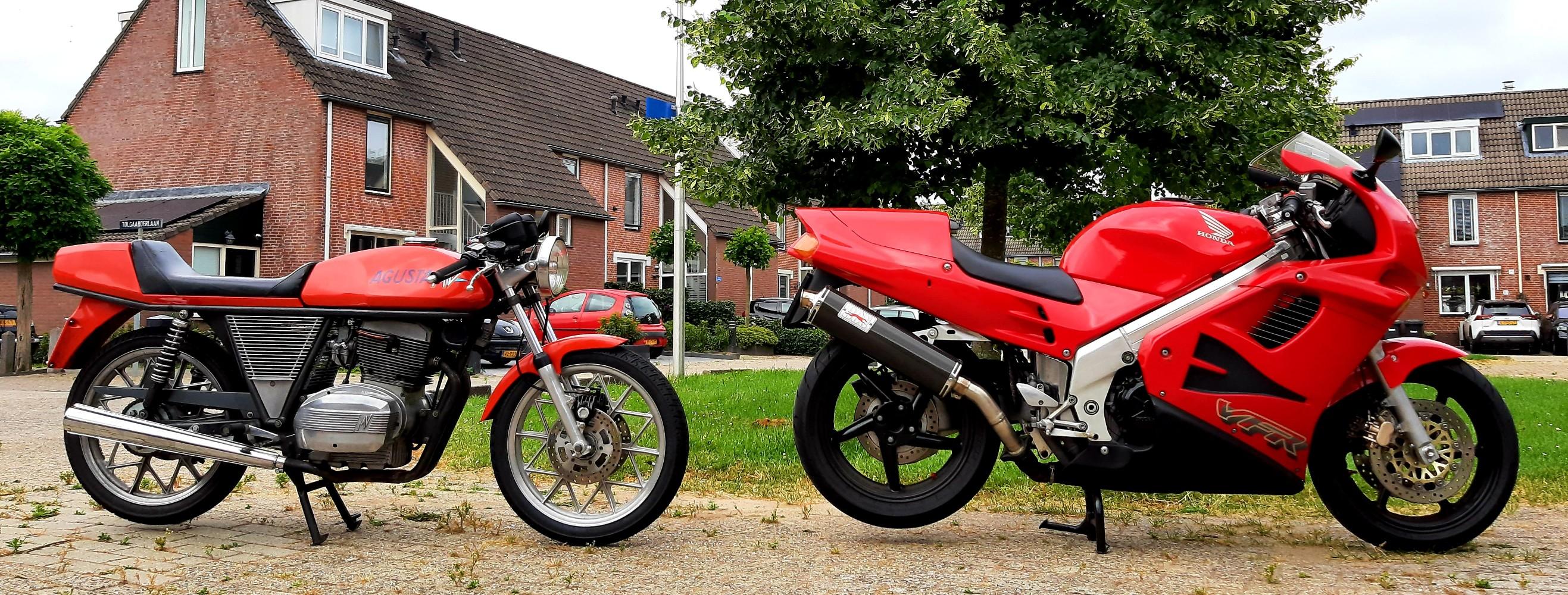
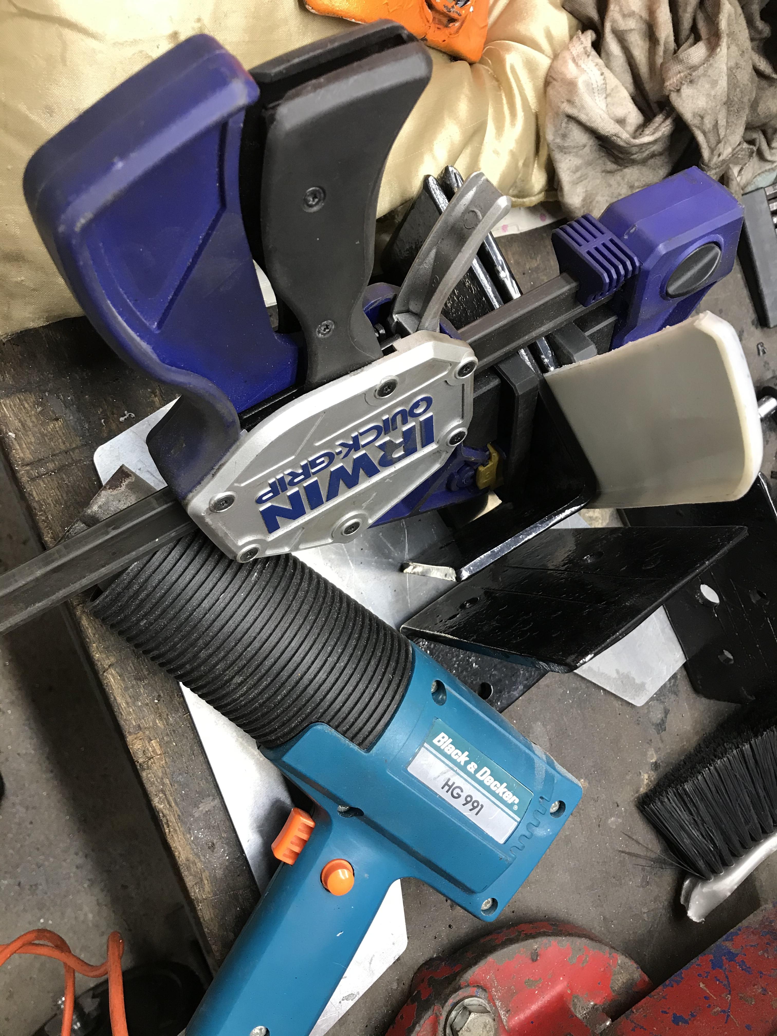
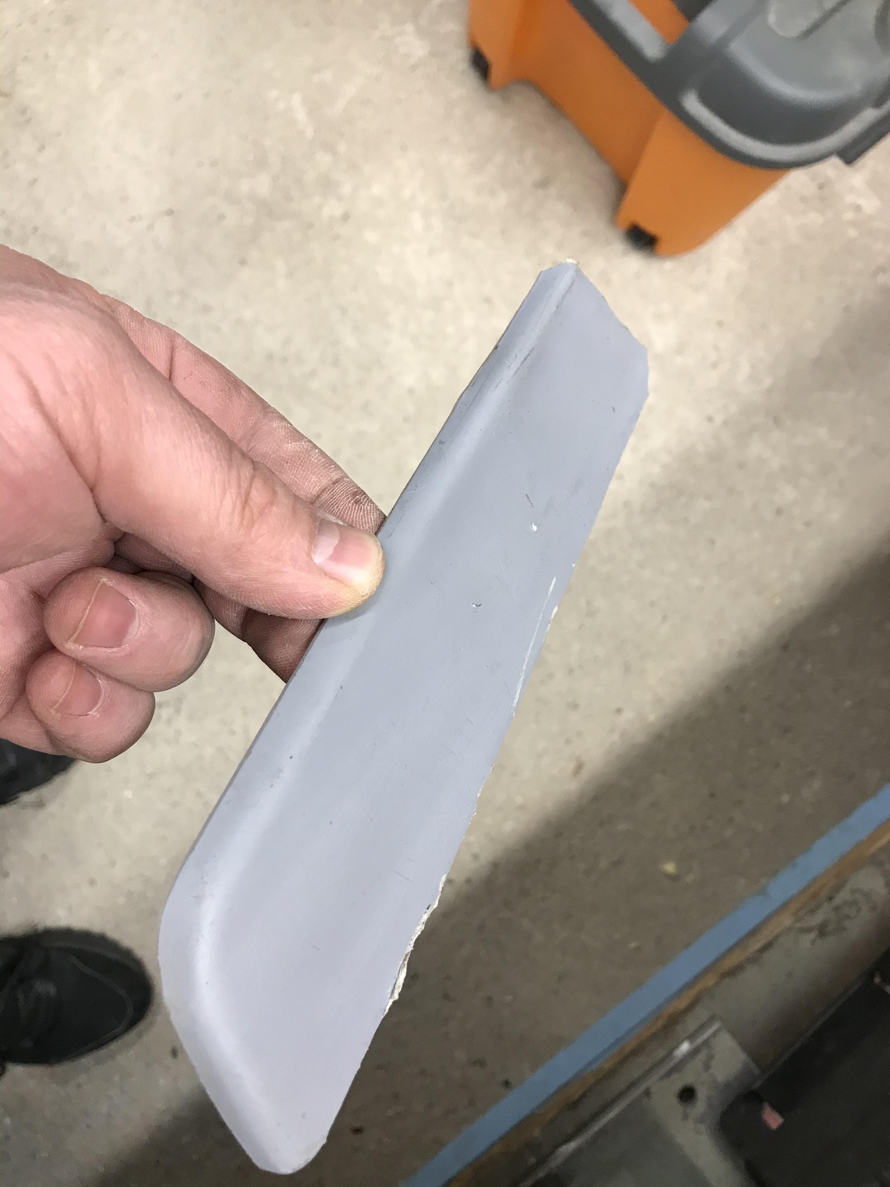
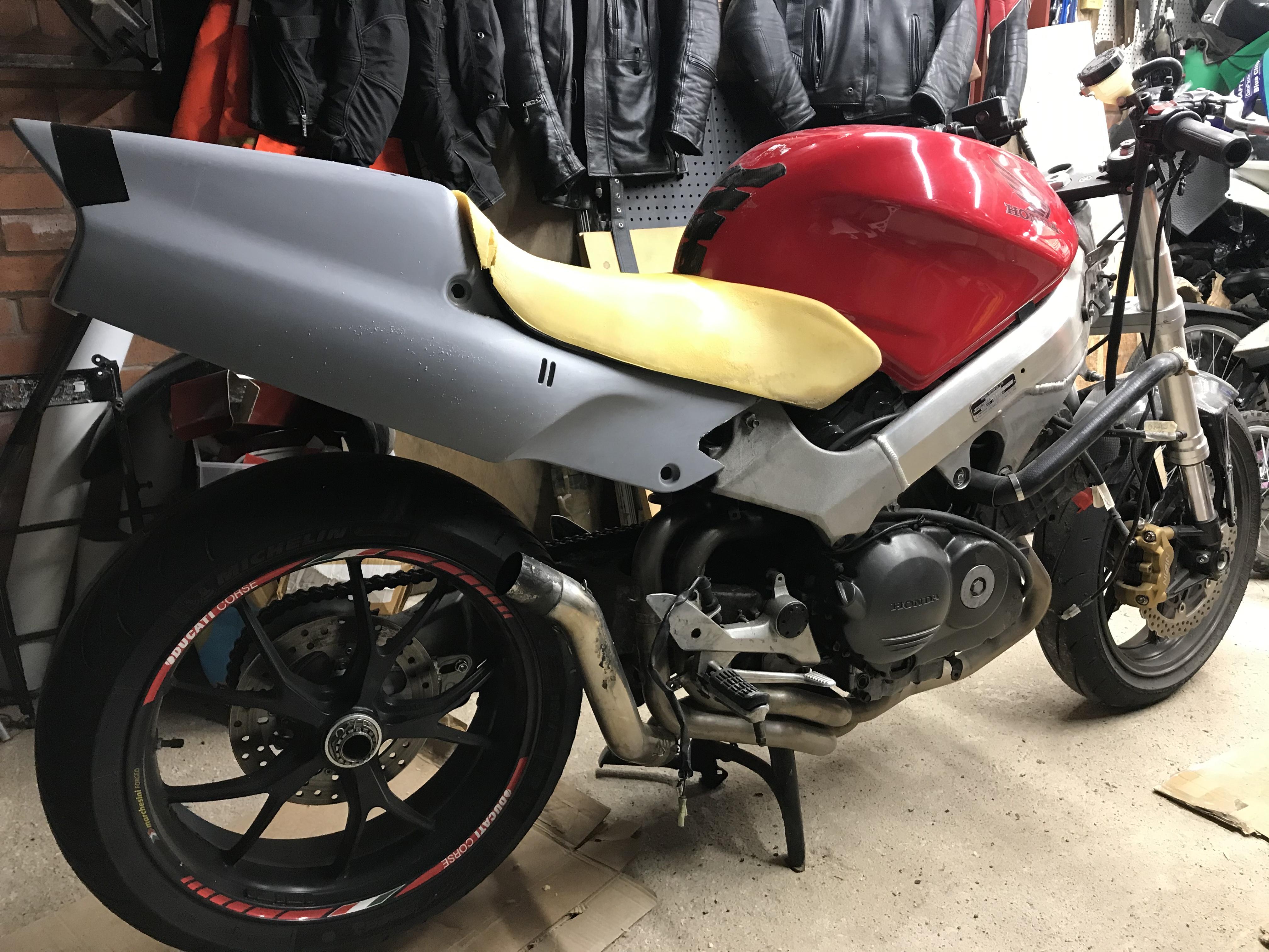
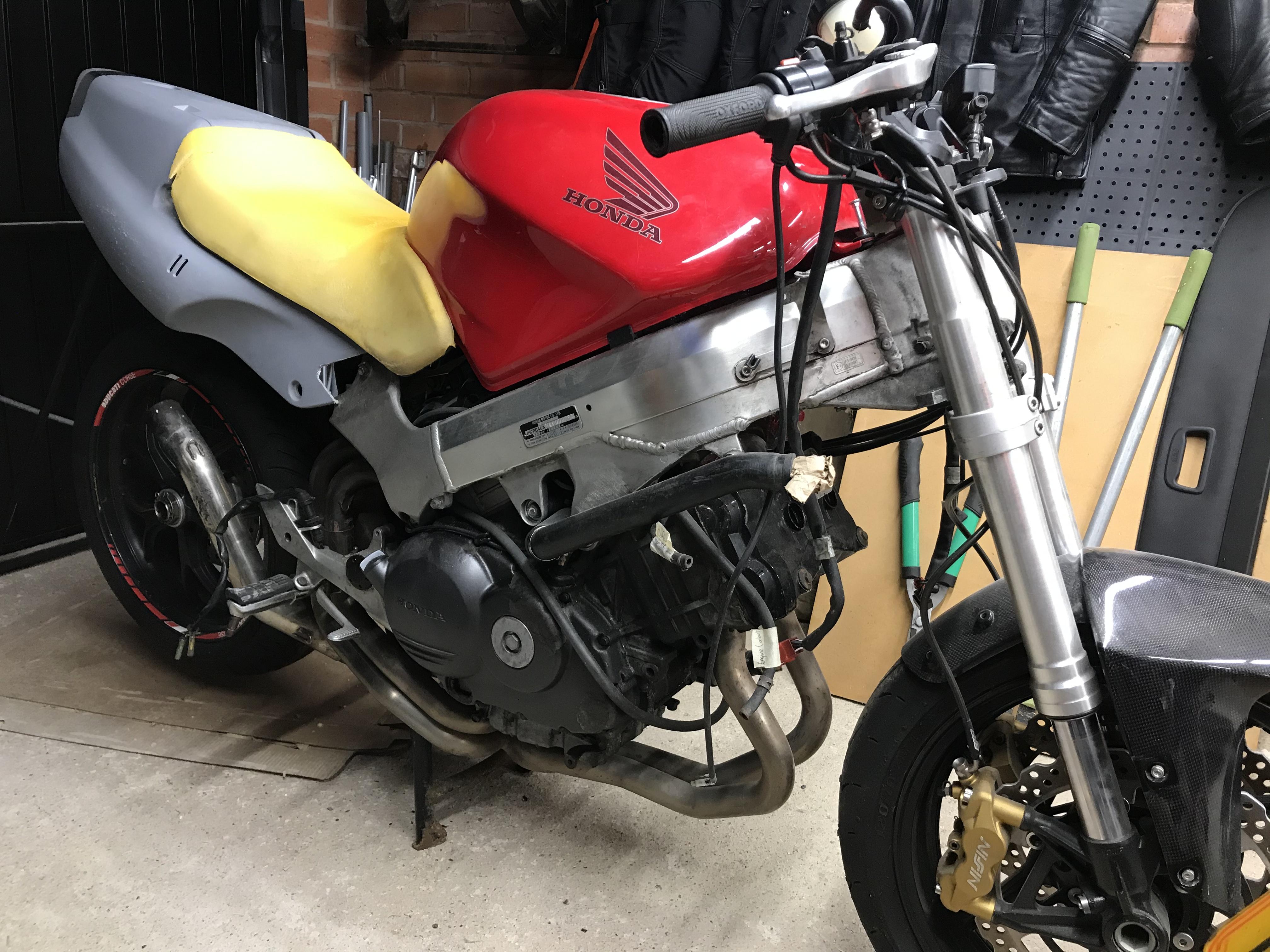
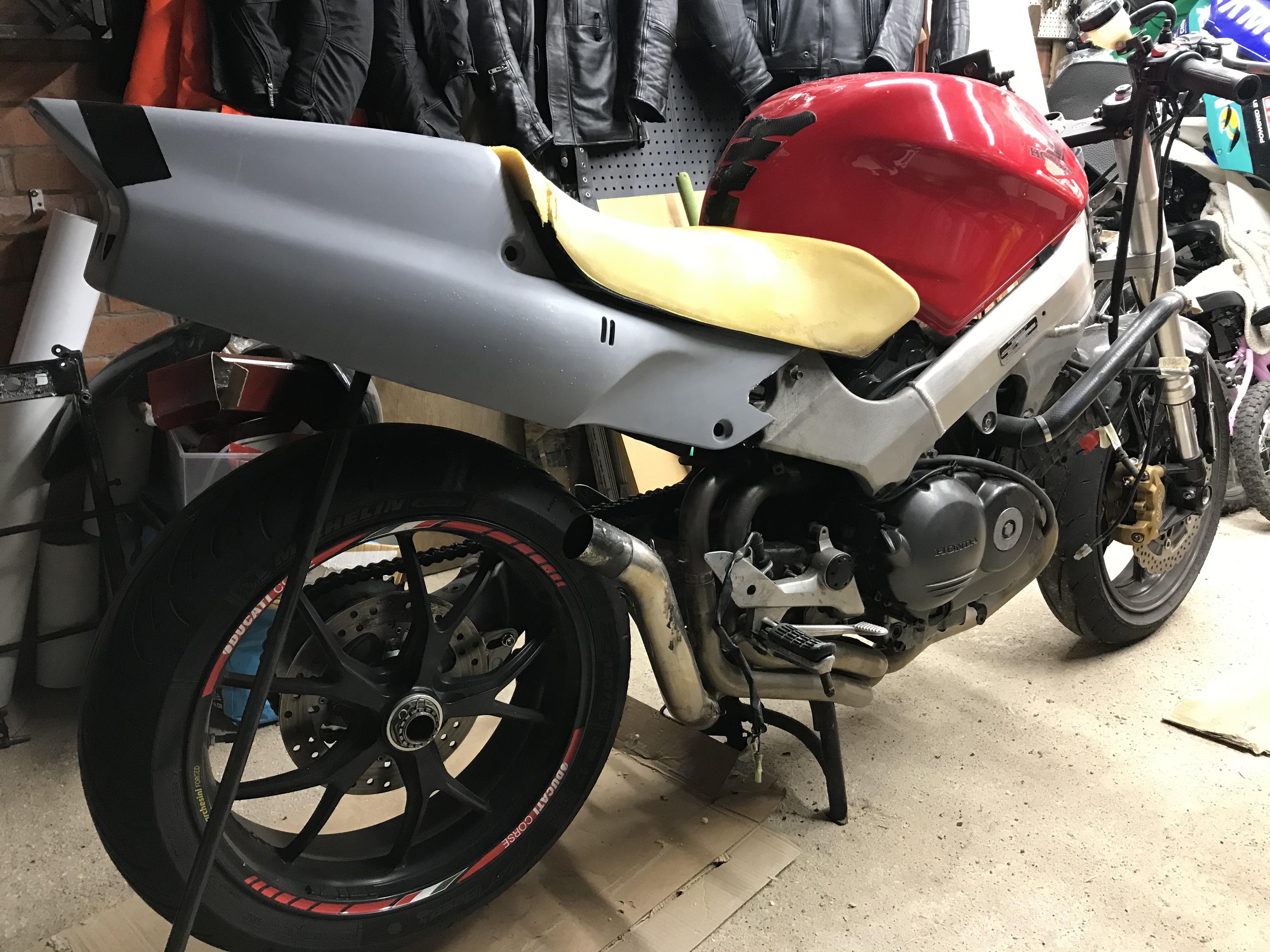
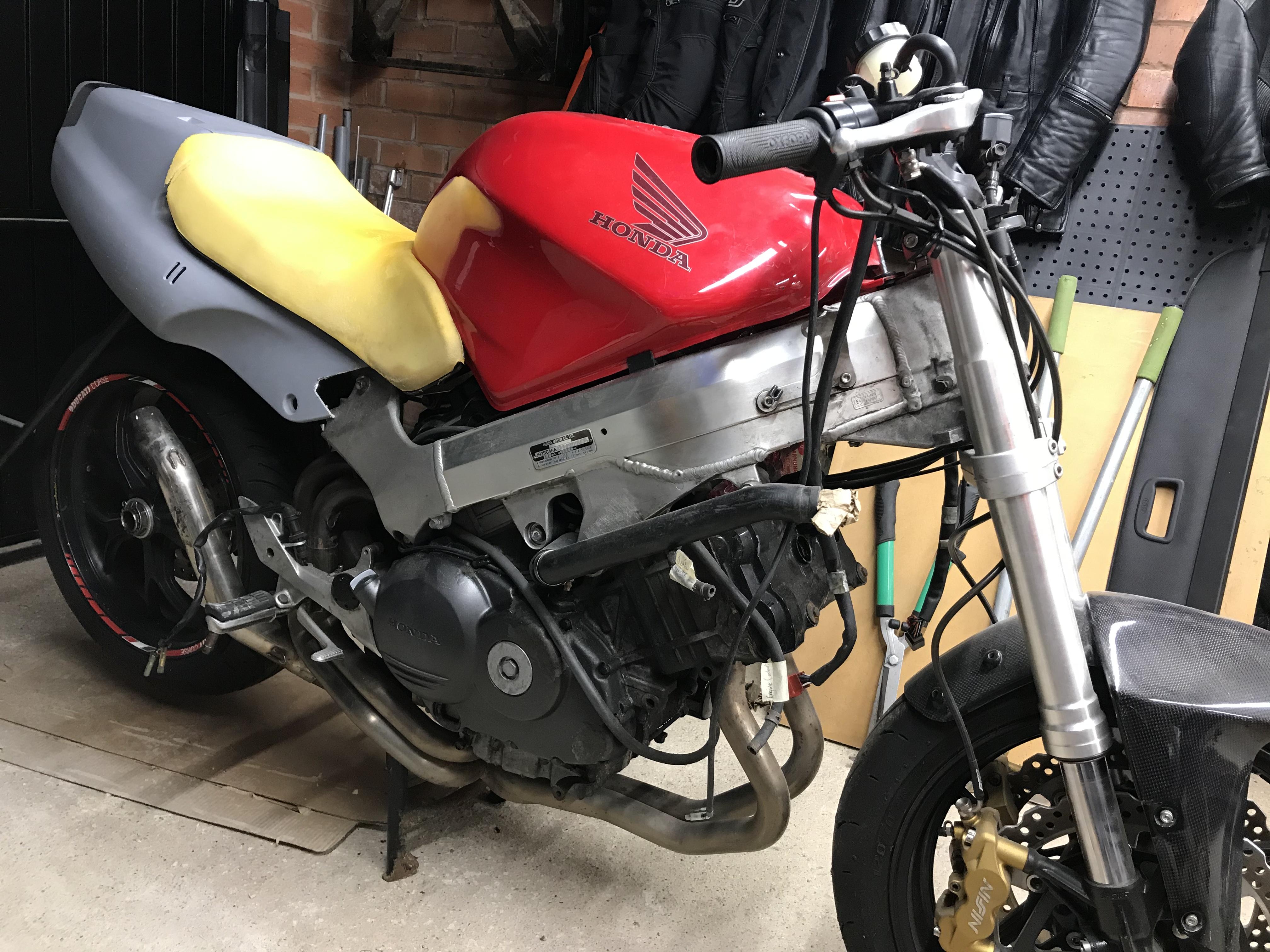
Another minor bit of progress - initial trial fit of NSR 250 MC21 tail fairing (Chinese plastics) and cut down 5th gen seat. Still needs a great deal of sculpting for both seat and fairing, but it’s a cautious start. Now just need to settle on the rear fairing angle and build a subframe. Which one do you prefer? Slightly upward pointing tail: Or slightly lower pointing tail: The MC21 is a much smaller/narrower machine than a 5th gen and the tank is narrower too. The MC21 fairing sculpts inwards at the front and fouls against the 5th gen frame, making it impossible to line things up properly. So I cut the offending pieces off and straightened them with a heat gun, some old angle iron and a clamp. You can see where I cut them off in the previous picture; there’s a gaping hole just where the fairing meets the main frame. Below you can see the grey plastic piece sandwiched between two black angle iron pieces and a blue Irwin clamp. By the way, these Irwin clamps are amongst the most useful tools I’ve ever bought! Came out straight enough with minor ripples that will sand out. Can’t tell it was ever “sculpted” in the photo. The idea is to glue them back on (solvent welding) but if I was doing this again I’d just have bent them on the fairing without cutting them out. Now can somebody please tell me why the MC21 has a NACA duct on the rear fairing cover? What purpose does that serve other than to let rain water in? And one more thing: why does the 5th gen have a sculpted crease on the tank (where the seat meets the tank) and no fairing to go there? It seems like they initially planned to extend the rear fairing and cover that hole where the rear cylinder is visible but then changed their minds. Maybe to let hot air out and stop the rear cylinders overheating?
1 point
-
I bet there was an air bubble trapped in that run. Air bubbles can cause poor cooling. Otherwise distilled water is a better coolant than “coolant”. The only reason we mix water with other stuff is to stop internal corrosion.1 point
-
Well, this may be a long shot, but I do recall a guy who incorrectly assembled the clutch Slave Cylinder. He actually fitted the slave piston back the front! It caused the same effect, he also thought that the push rod was too long. Guess its worth checking.1 point
-
Most likely suspect (culprit) causing your issue is the “rebuilt” slave cyl, wrong parts/kit, piston in there not the correct dimensions, take it apart & compare to original part(s)? Grasping @ straws, but if everything else is correct...1 point
-
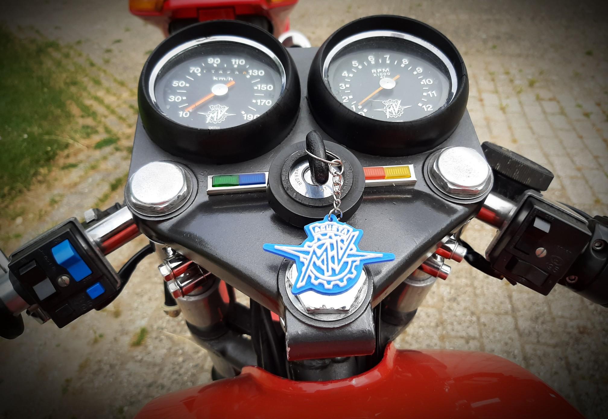
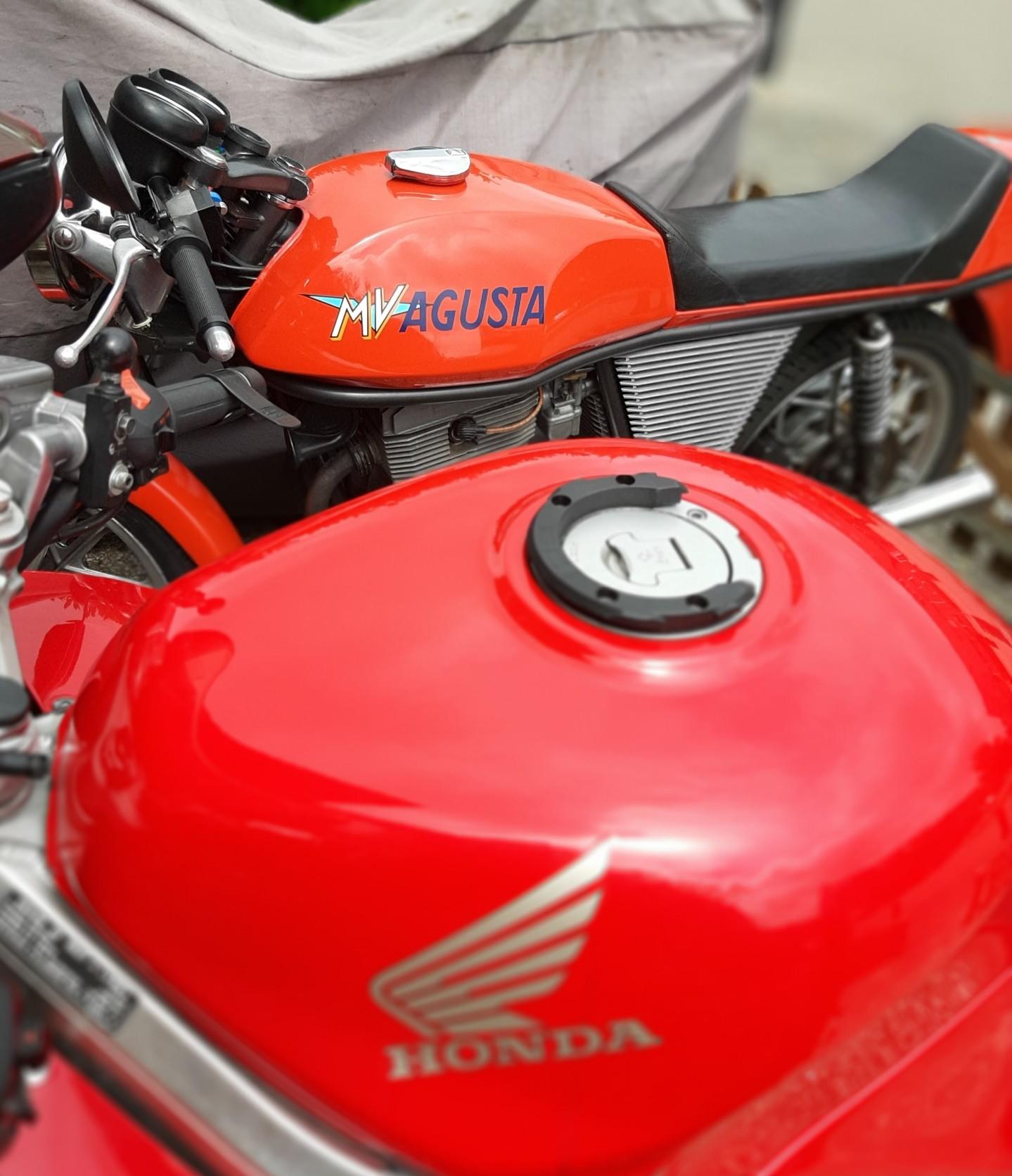
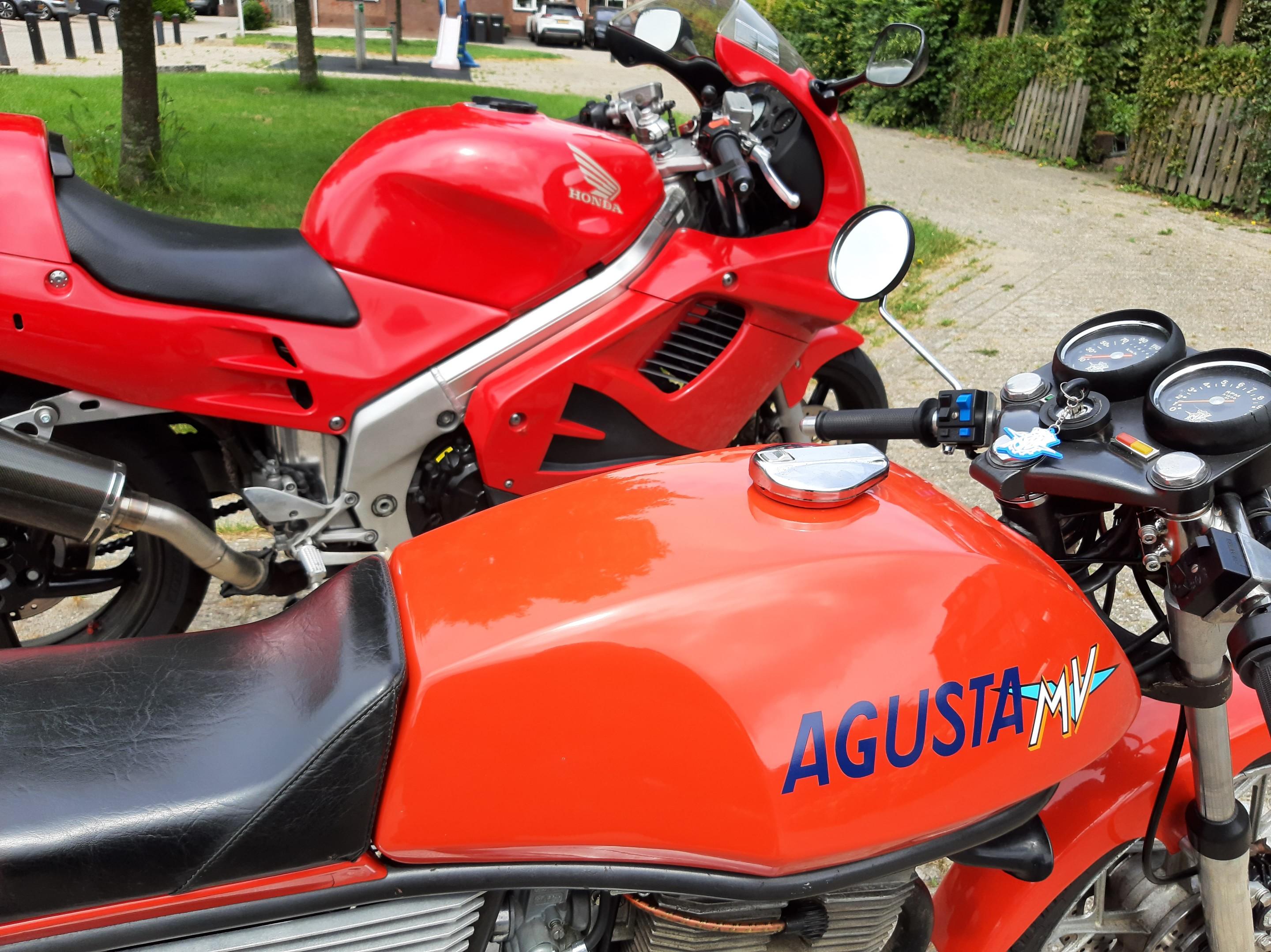
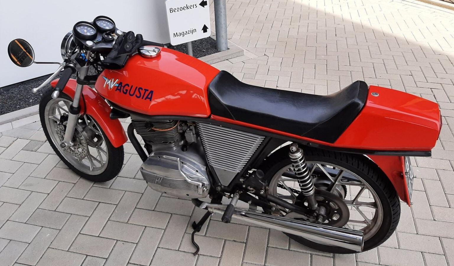
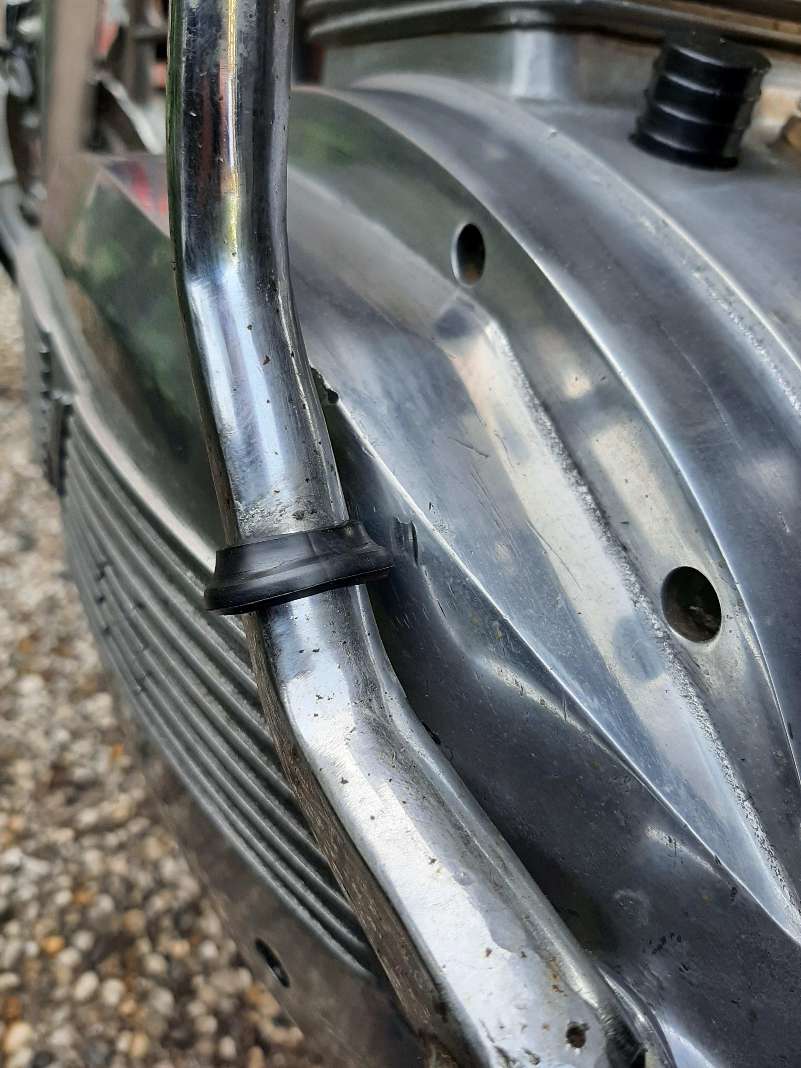
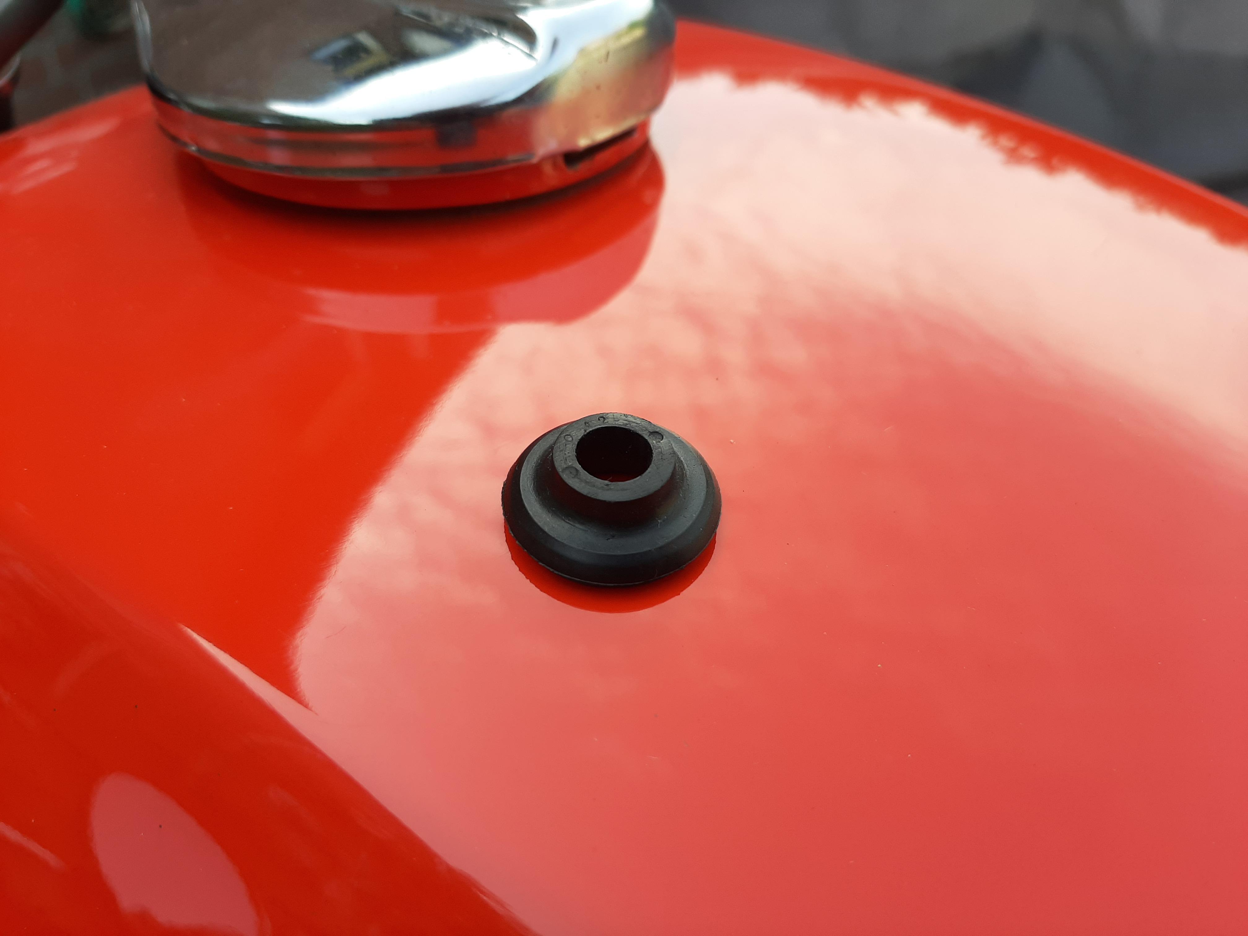
Change is good! Park Gilera, take MV! 'king hot today, but still got a good 3 hours blast.. 🙂 Typical..... Italian design is beautiful, but the kickstarter "cloinks" to the side.. Honda to the rescue! I rummaged through the box labelled "bitskeptfrompriorbikes" and founds this VF valve cover bolt rubber!! TADAAAAAA!!!
1 point
-
I'm not tracking with how this could be a hydraulic master / slave cylinder bleed issue. The default with the clutch lever at rest (out) is for the clutch to be engaged. Air in the system compresses and prevents the clutch rod from applying force to the clutch stack to dis-engage engage the clutch (slip). He's saying the clutch is out and the clutch is slipping, so air in the hydraulics cannot be the problem. If the slave cylinder is maybe partially seized or somehow the master or combination of parts are not allowing the system to release the pressure on the clutch rod, that could be an issue. Since the fluid was nasty when you changed it maybe there are some corroded parts or plugged passages in that could be the source. Since your clutch was slipping before it was serviced, that could warrant further investigation. Just to be clear - I think it's a matter of semantics or language translation, you mentioned clutch "oil". Did you mean hydraulic fluid? The master / slave system requires the correct fluid, an oil is not specified for that application. Once the hydraulics are sorted and known good, then it's probably worth going back over the clutch pack installation. Leaving a disc or steel out of the stack, or getting them out of order could be the problem - I'd be inclined to take it back out and double check your work, comparing to the factory service manual to see that everything is as it should be. I don't believe you mentioned - did you use OEM parts, or aftermarket? If the latter, it would be worth measuring them to be sure they match OEM specs for the components.1 point
-
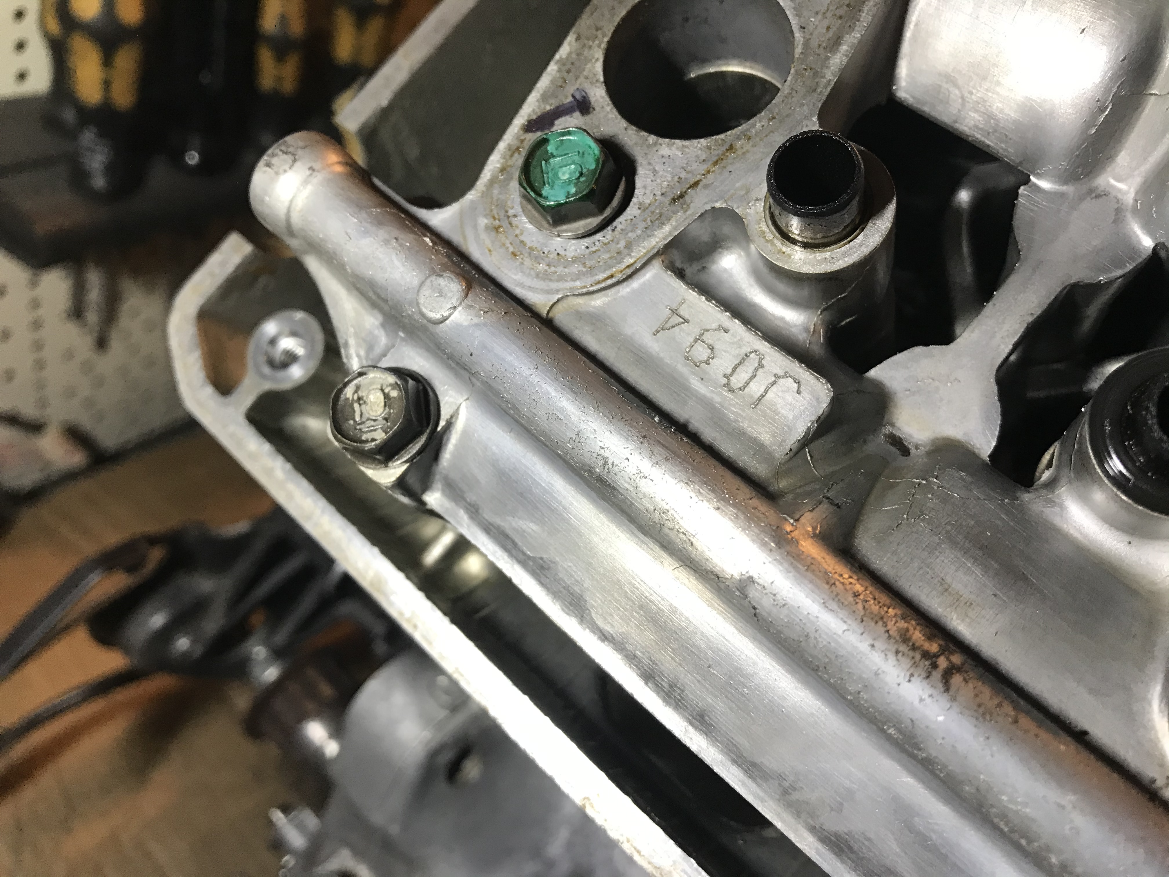
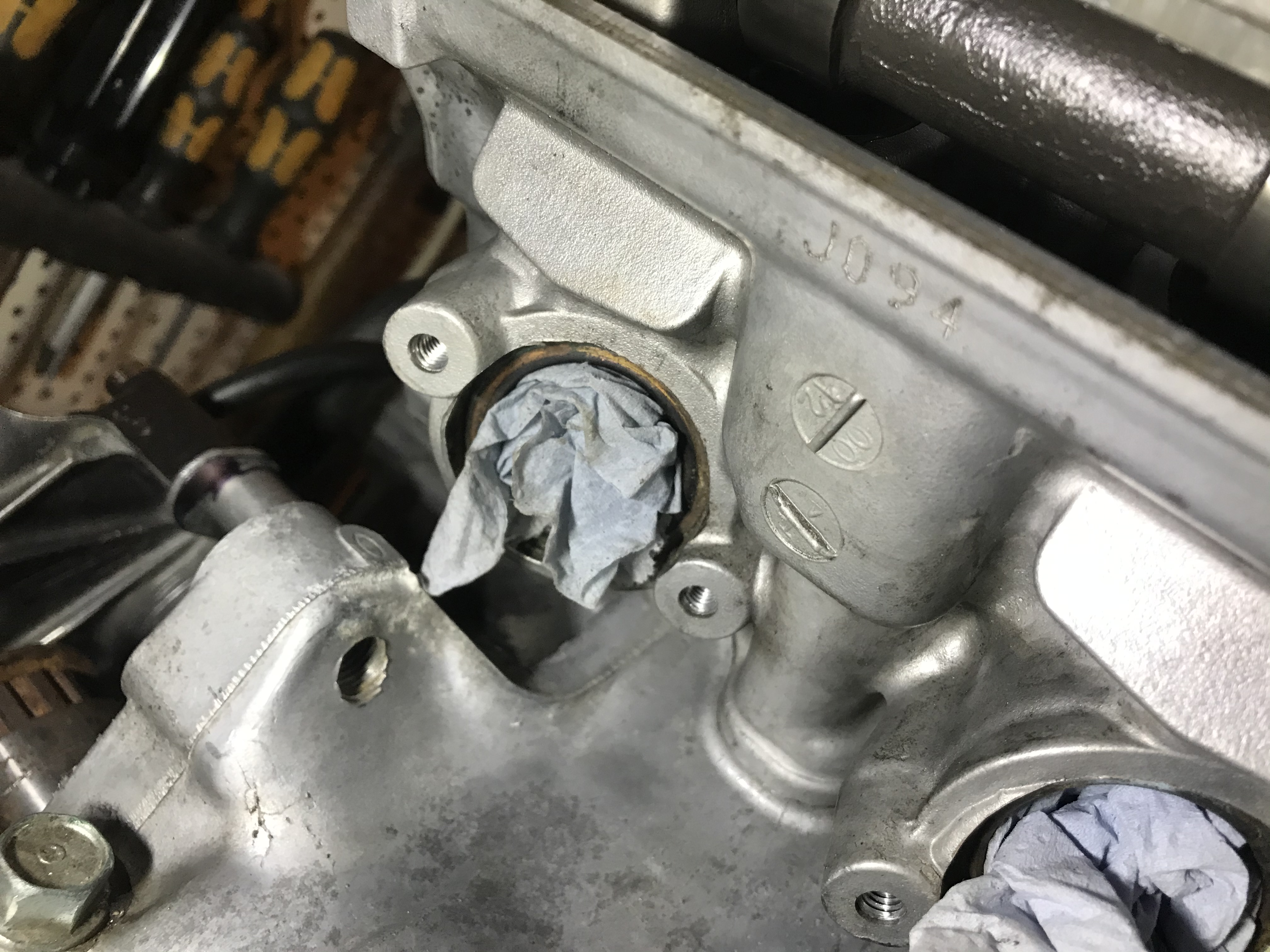
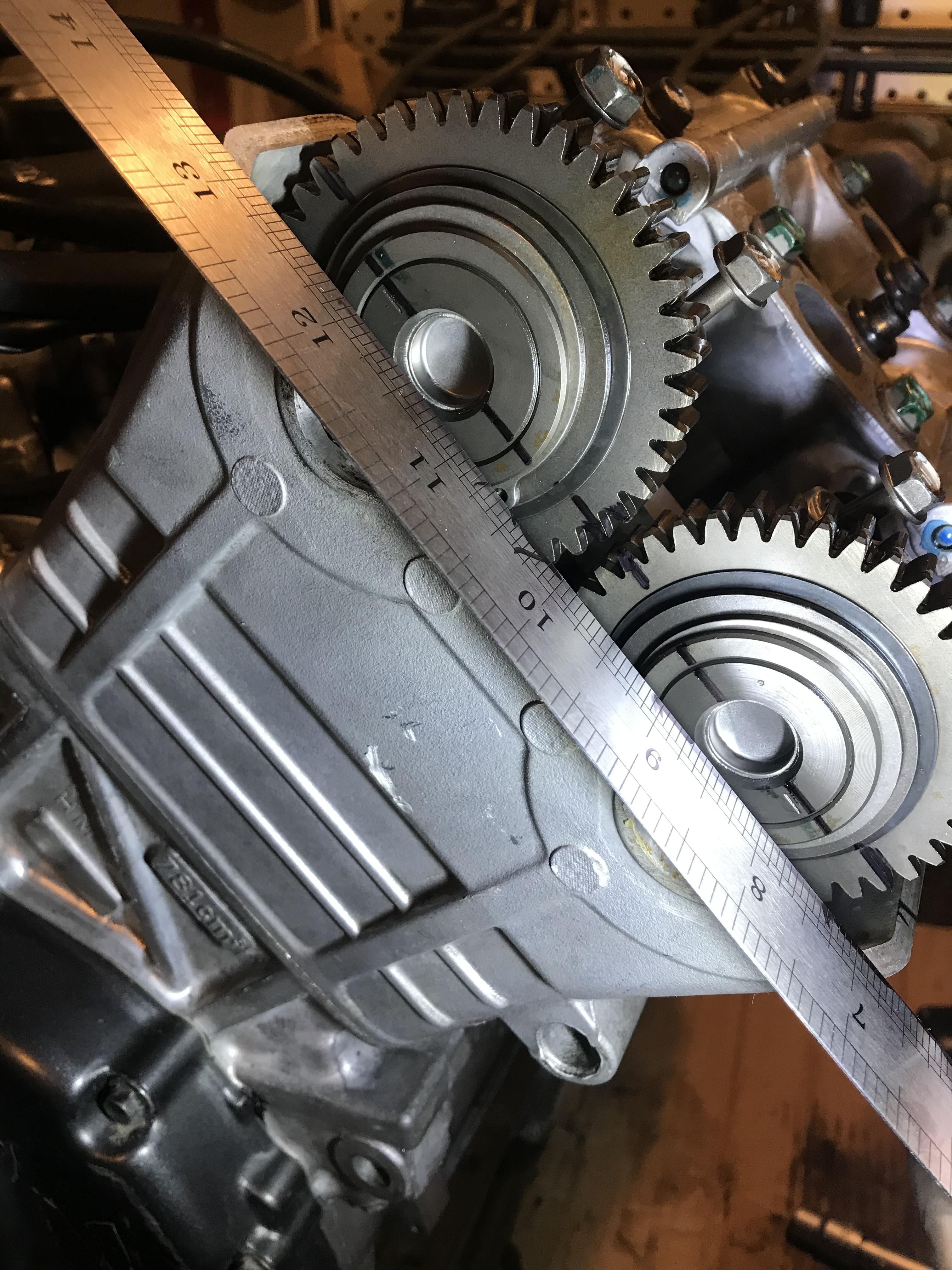
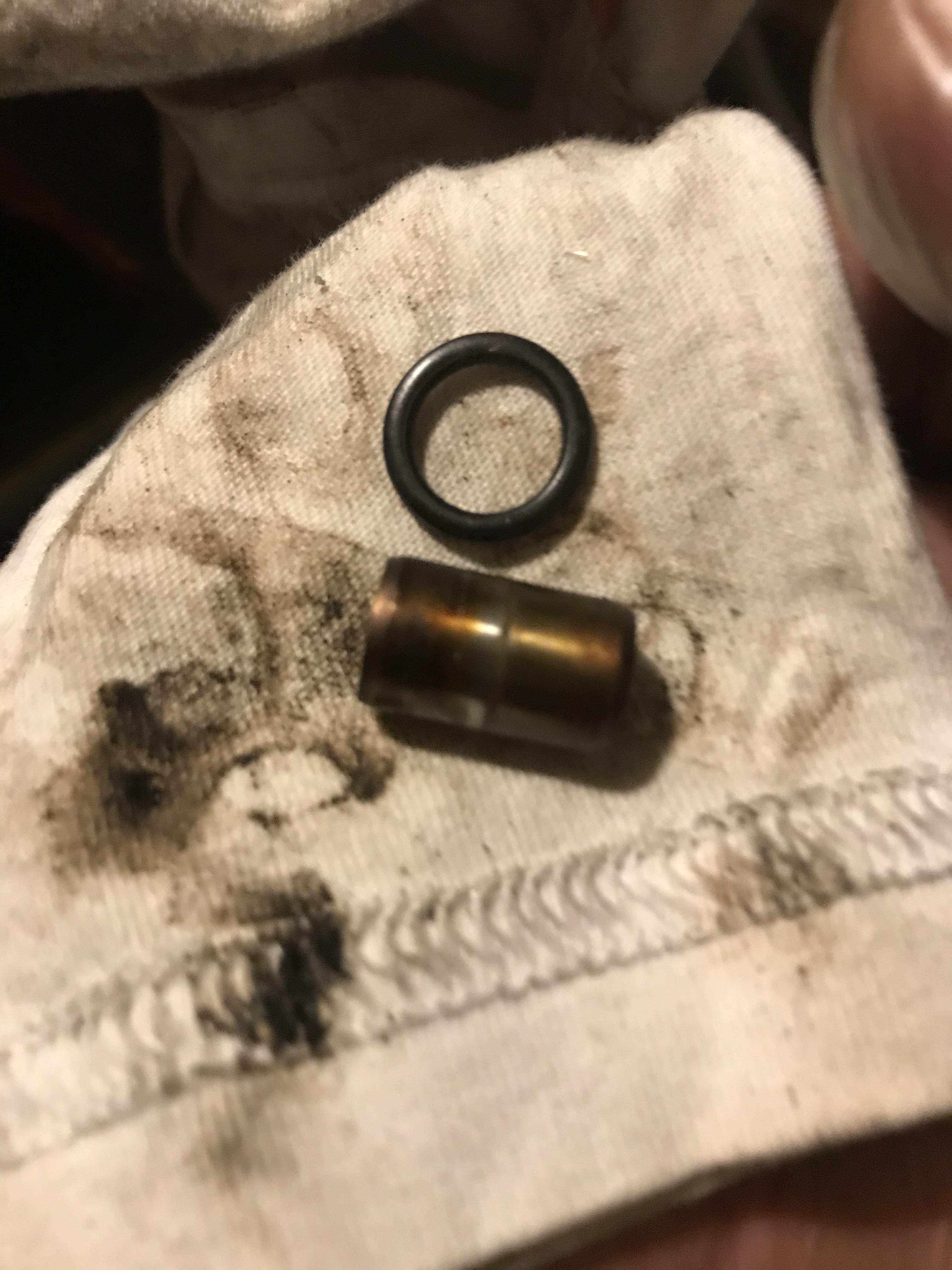
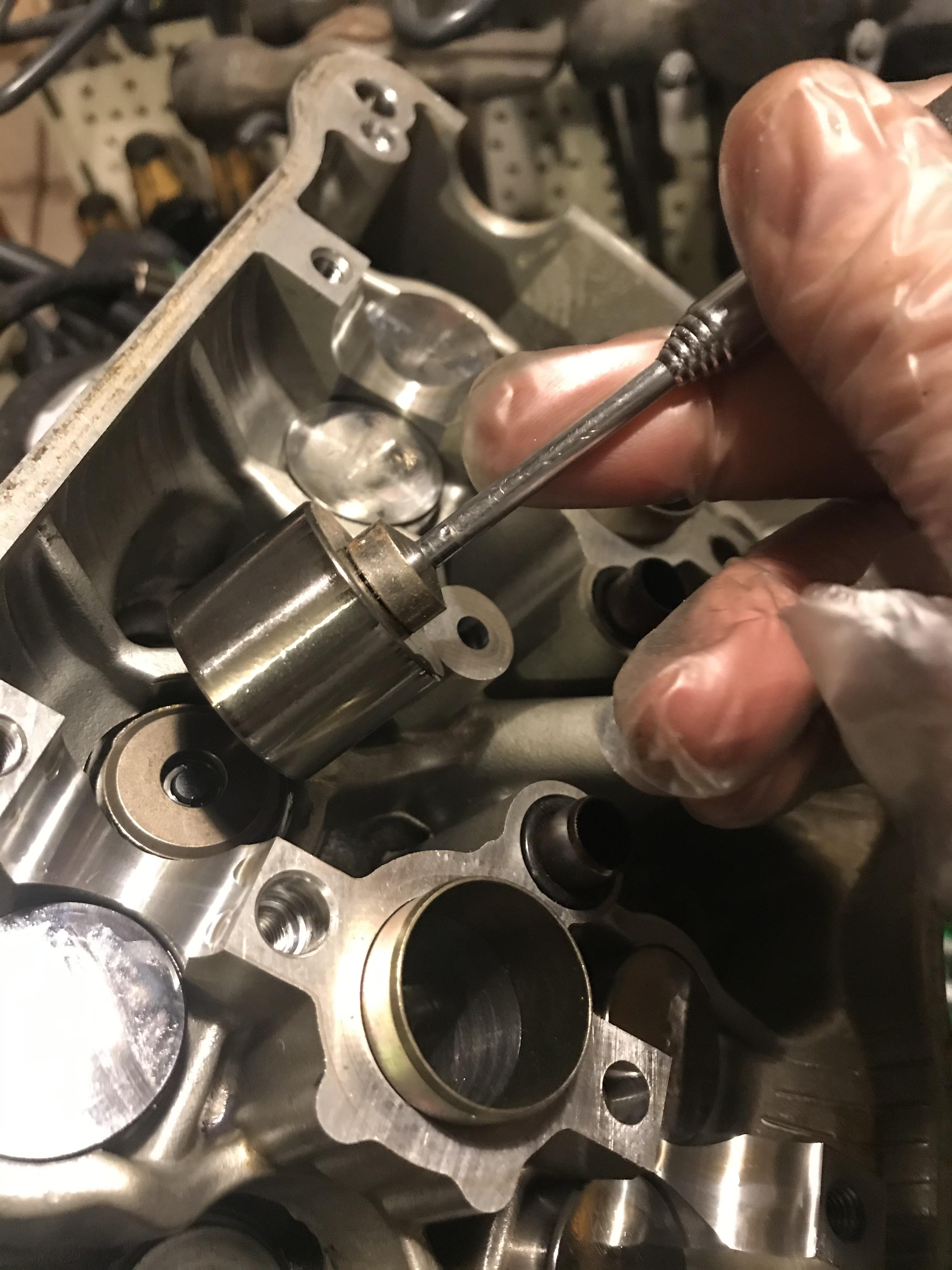
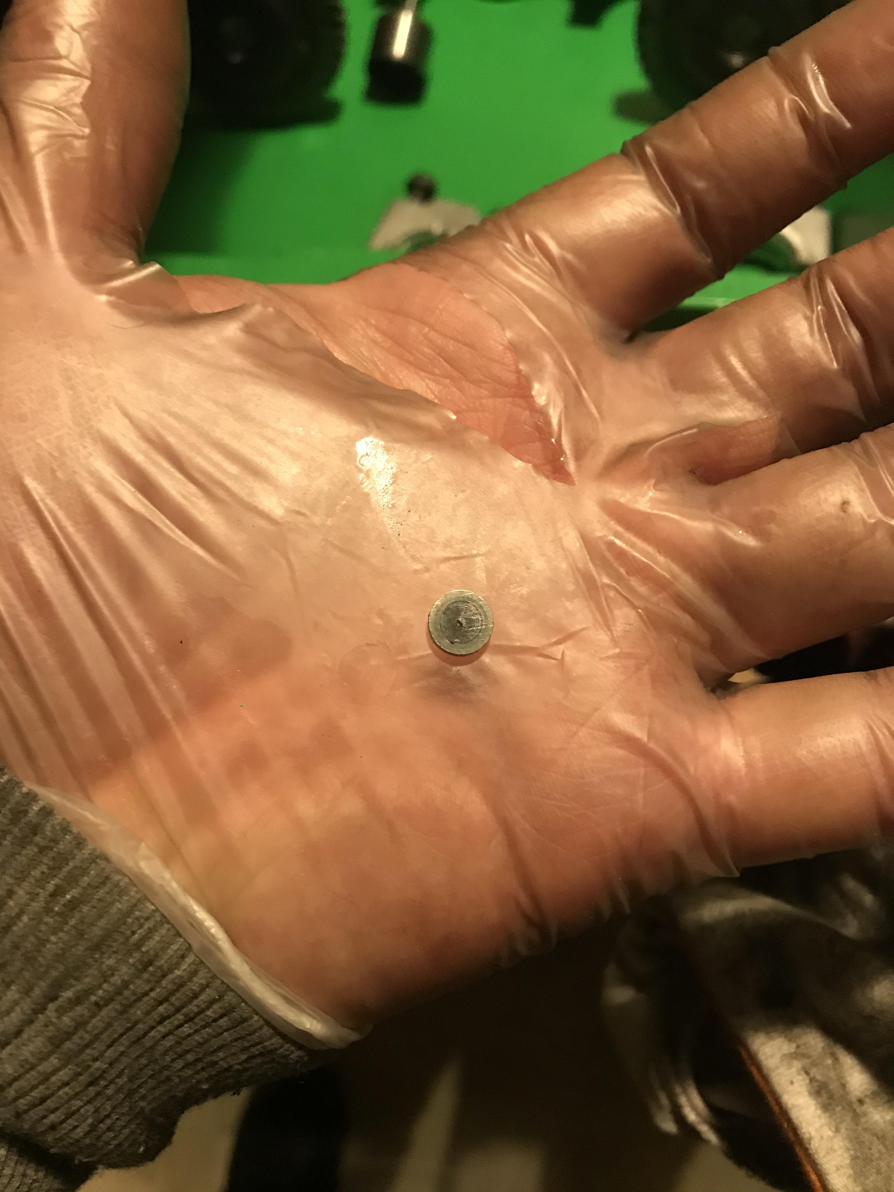
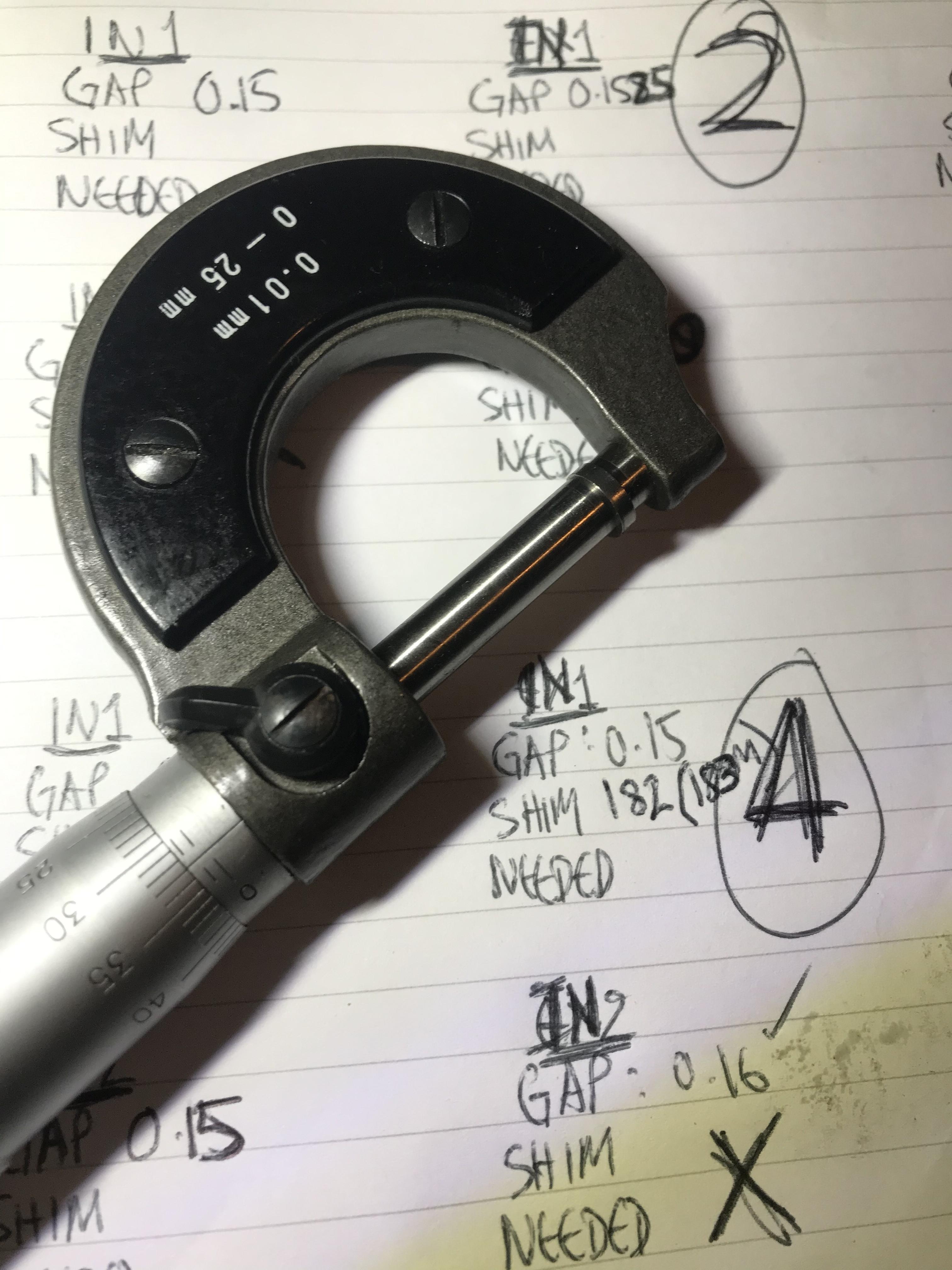
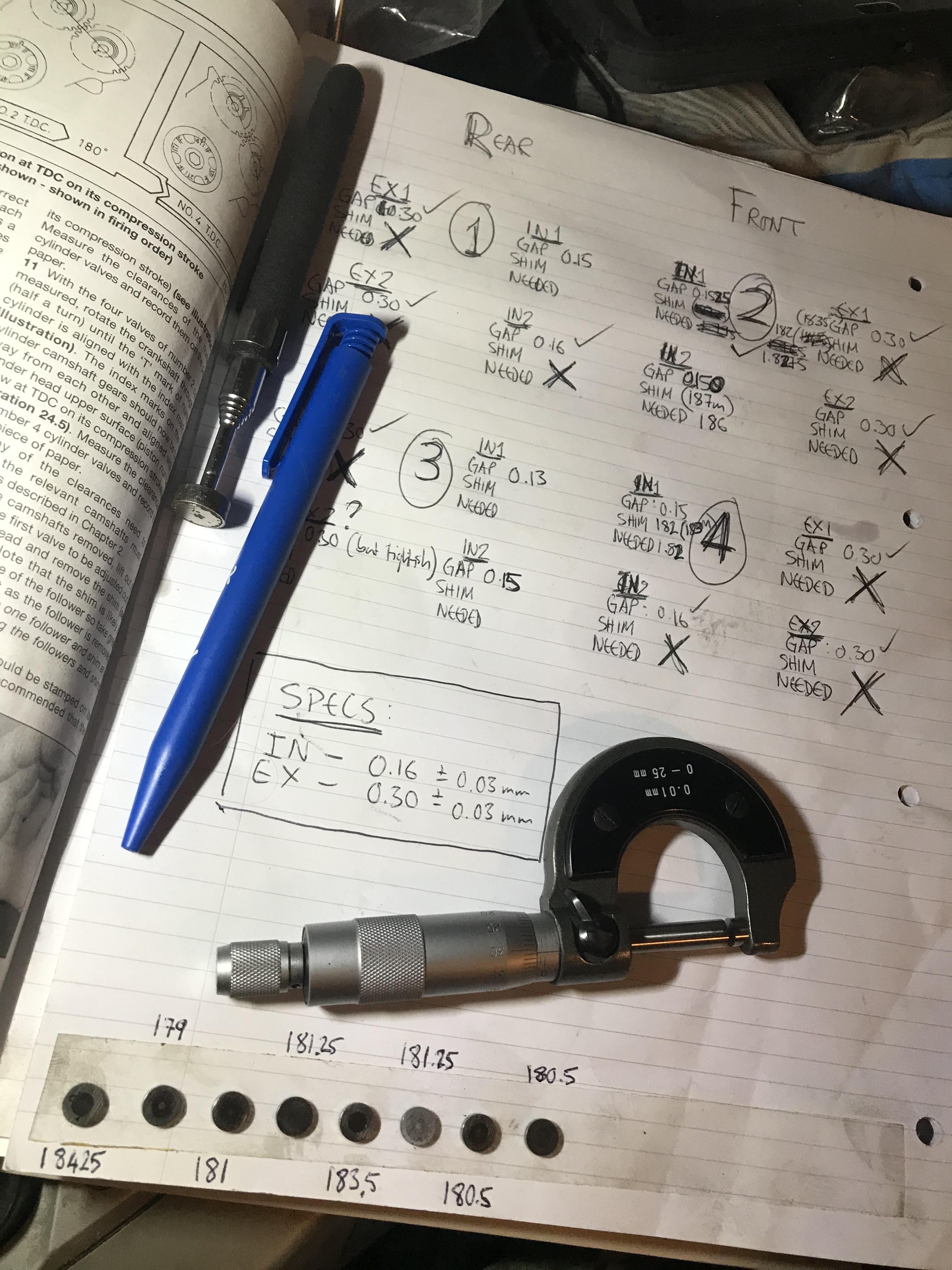
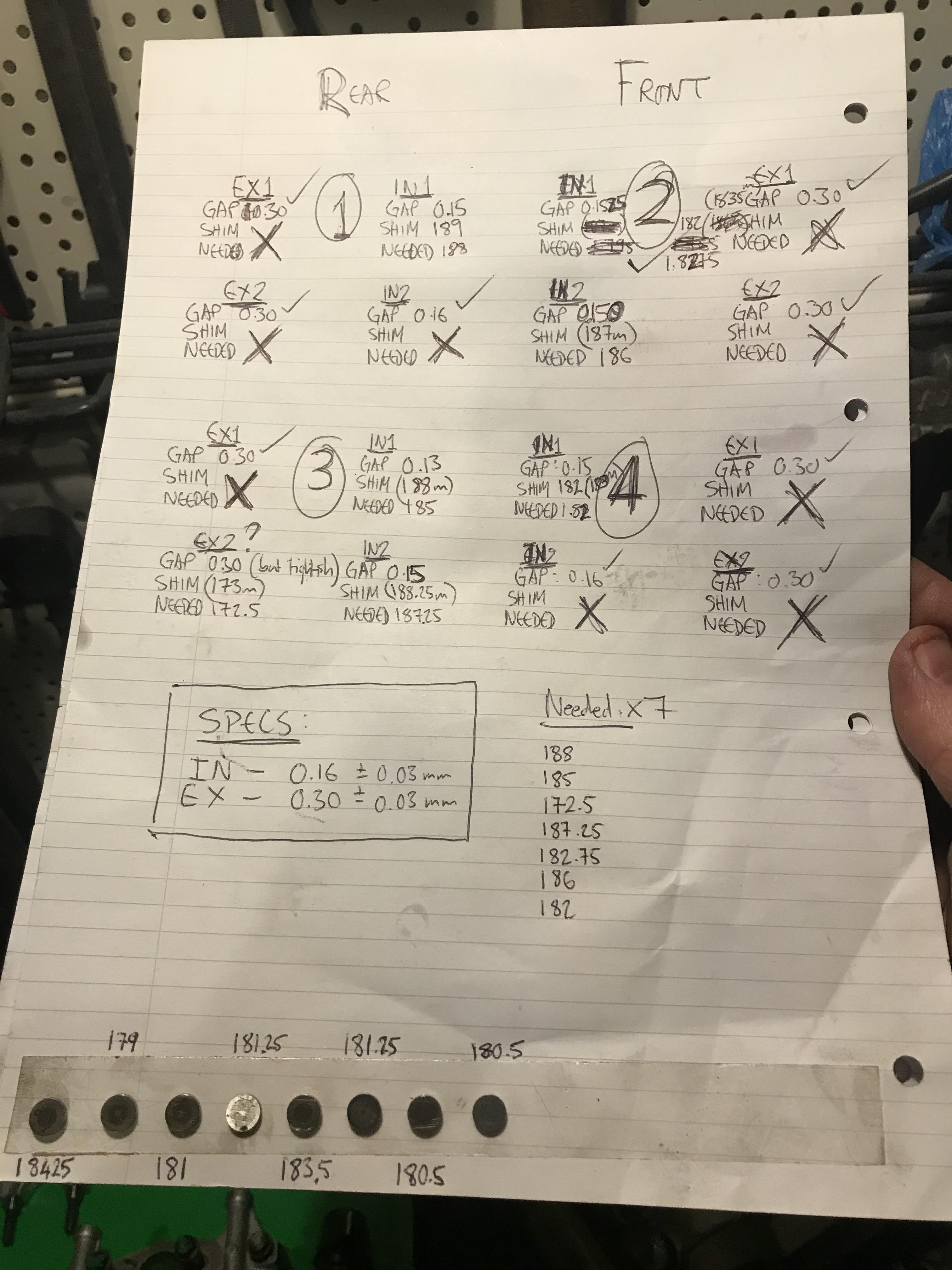
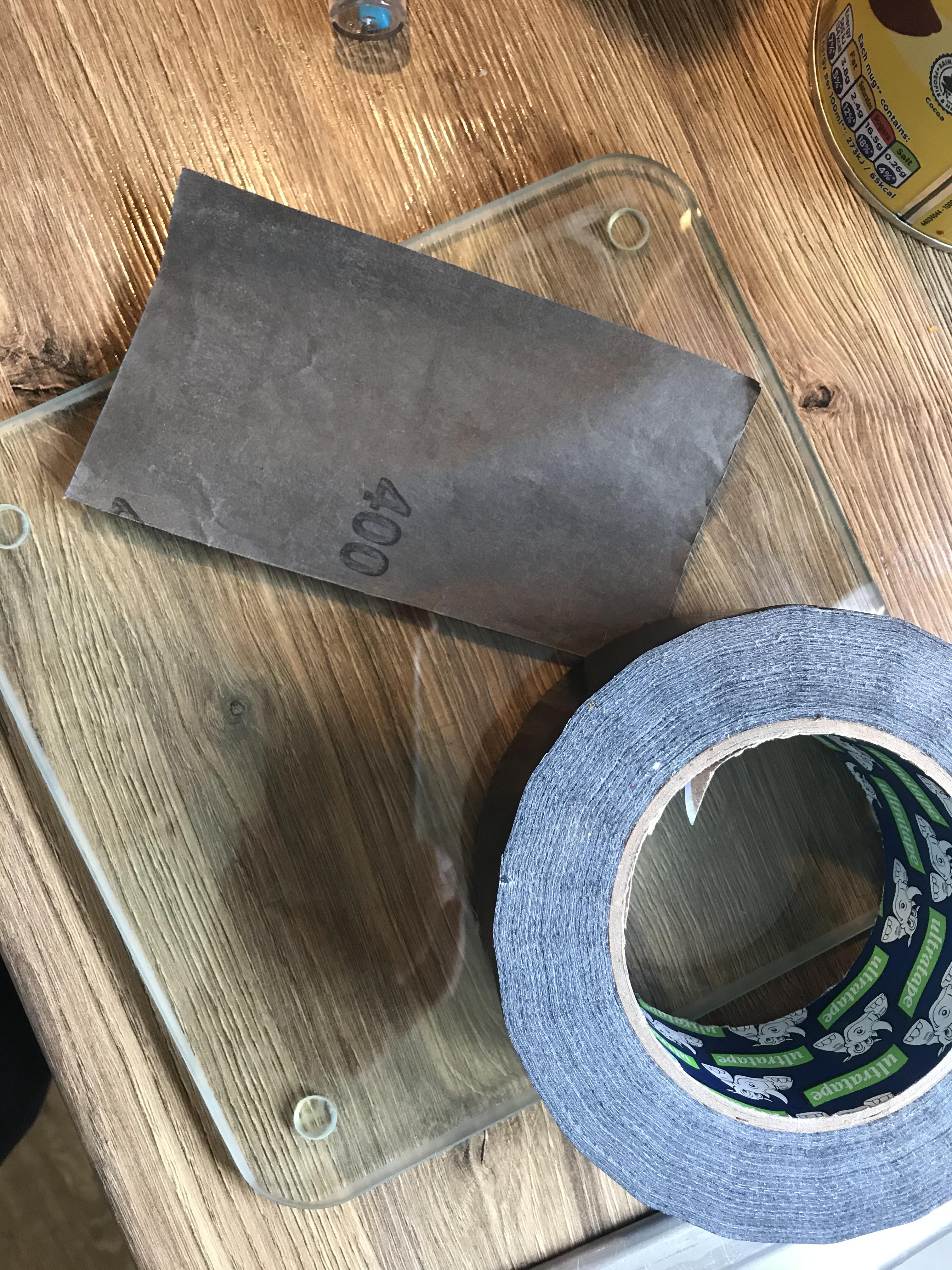
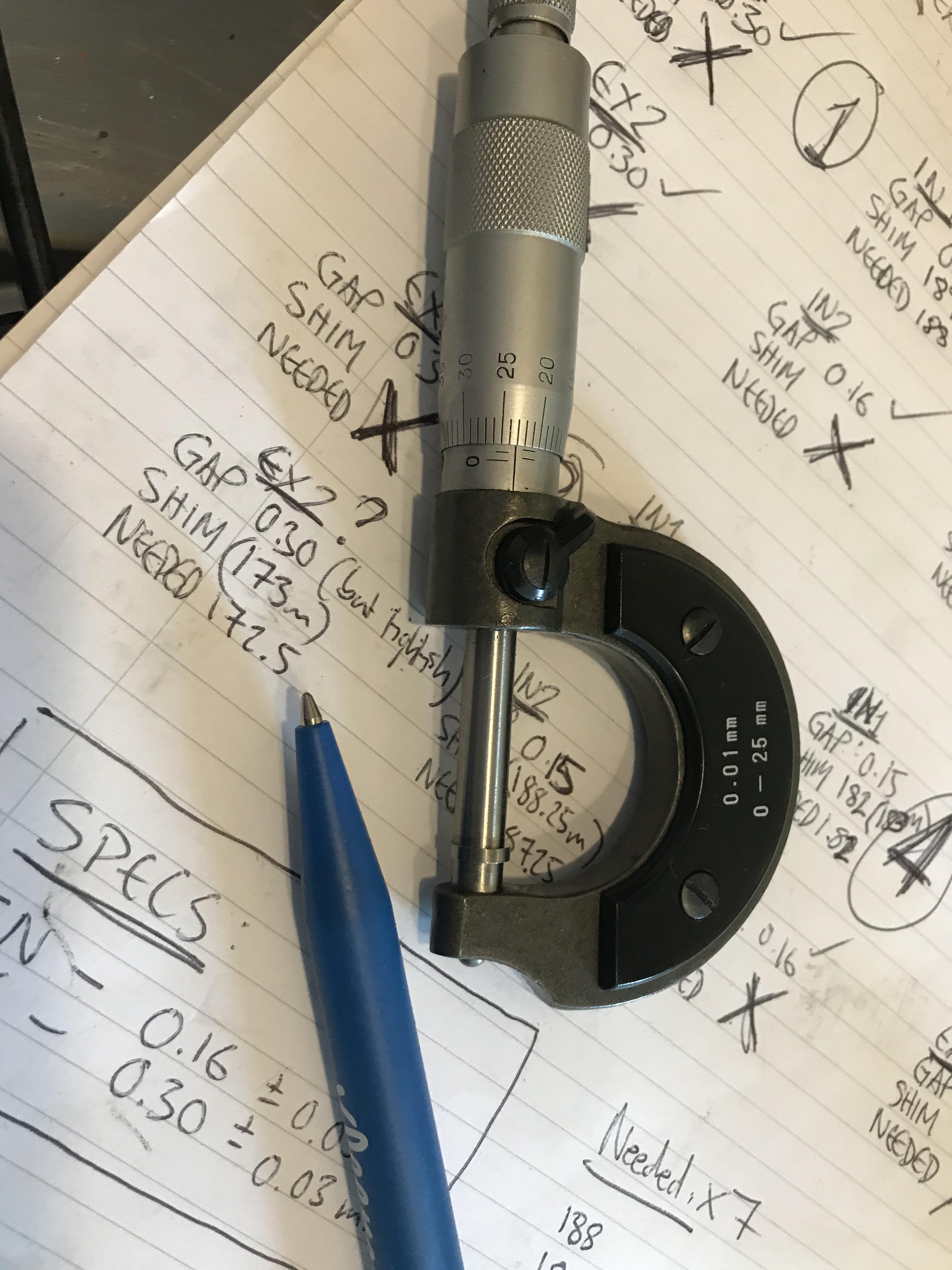
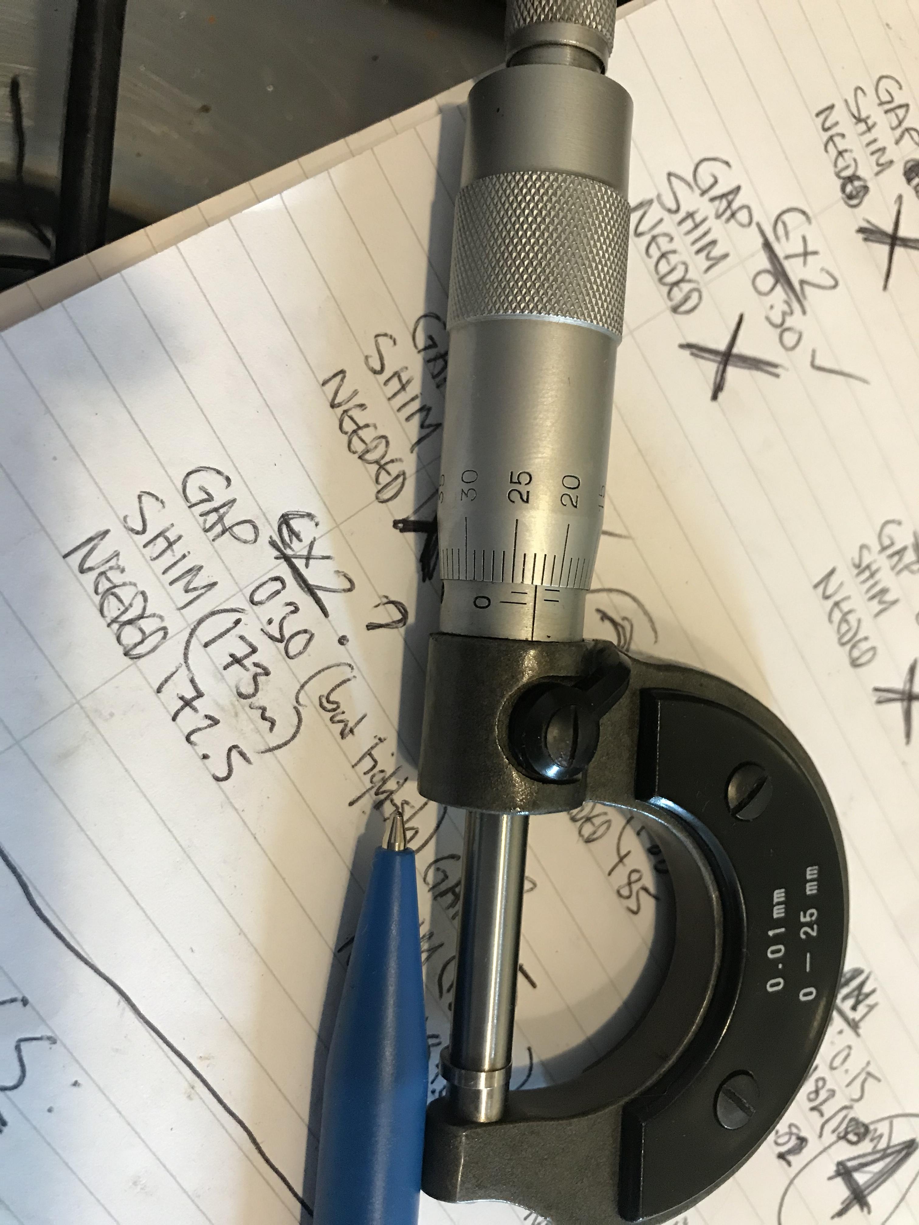
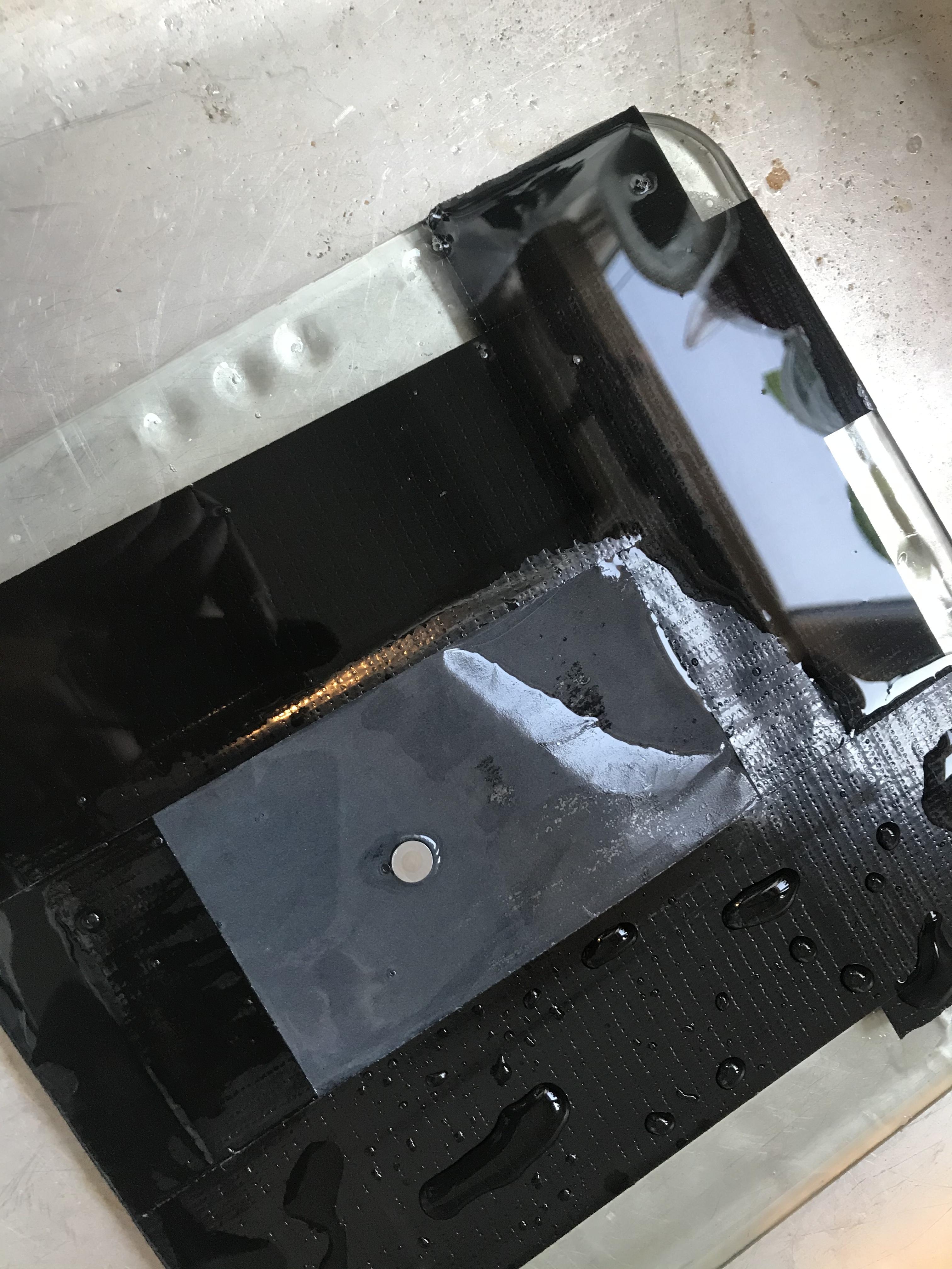
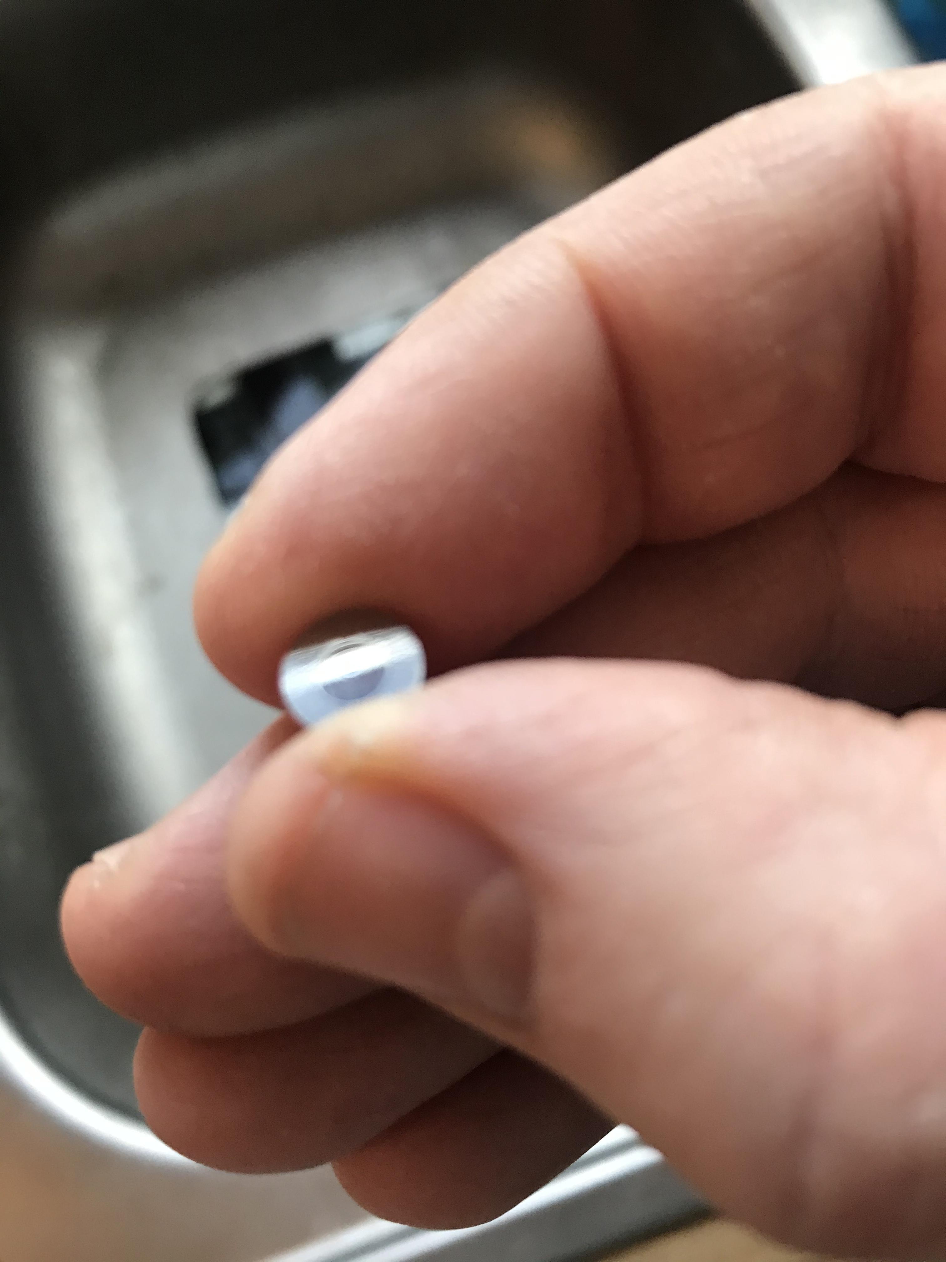
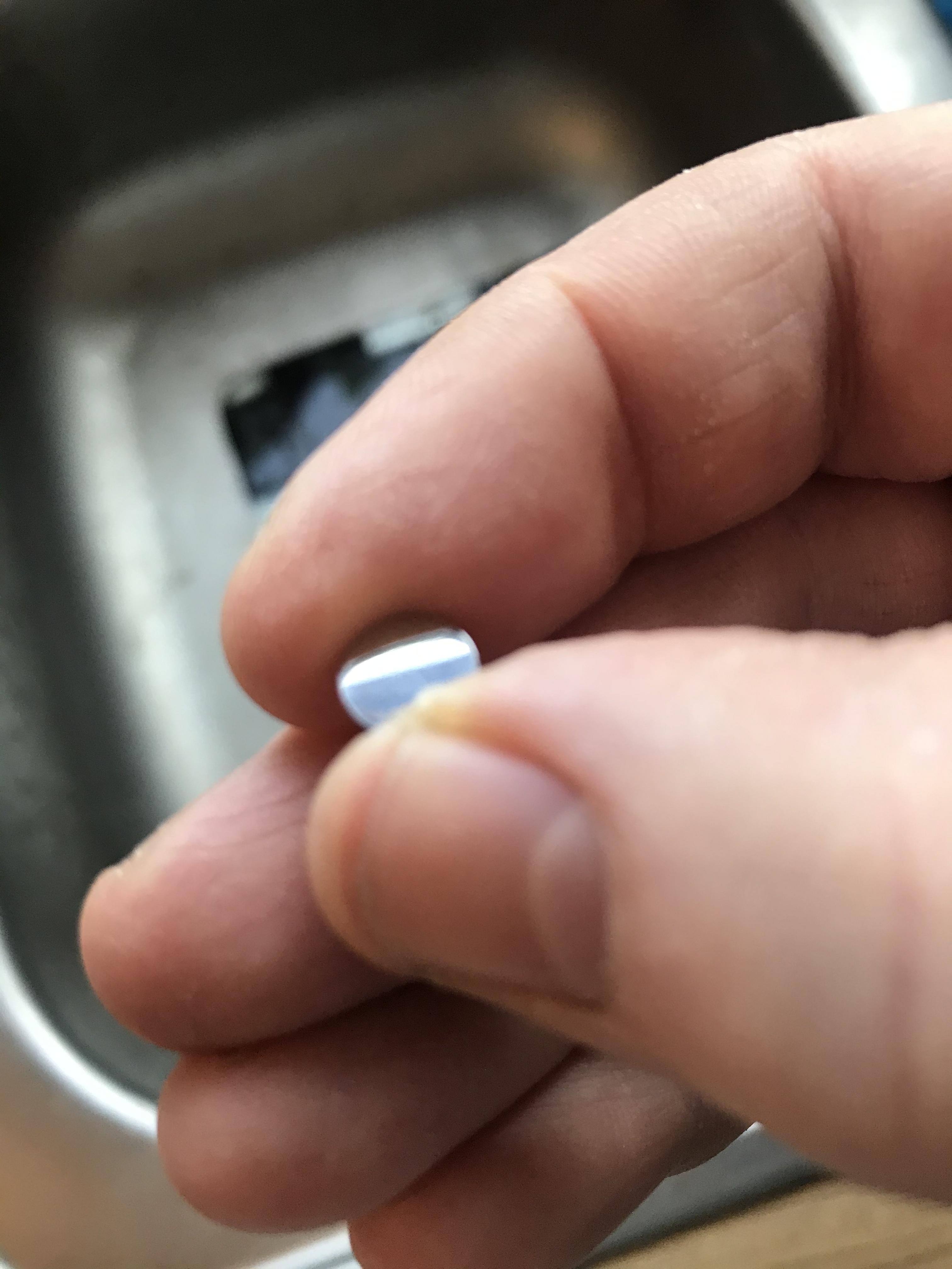
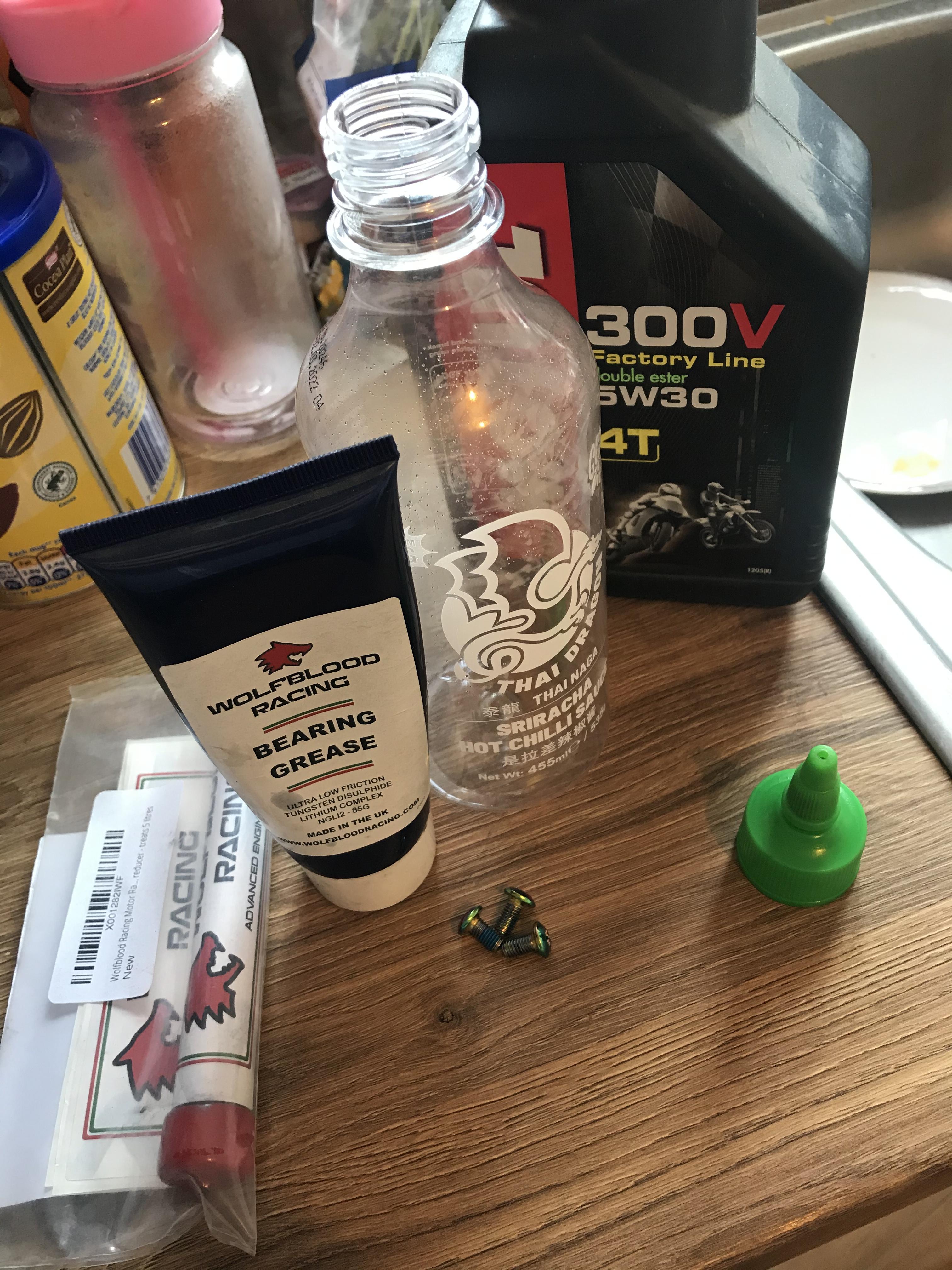
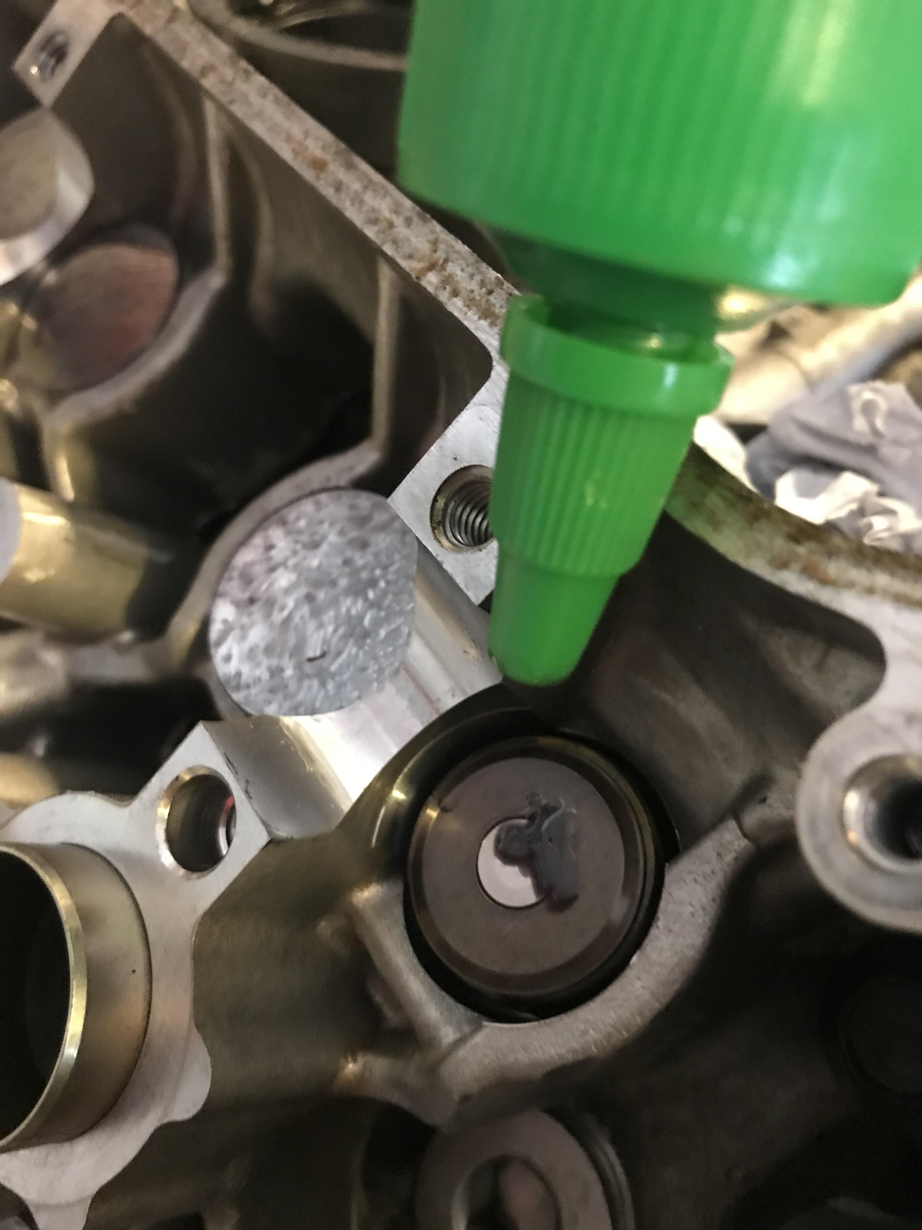
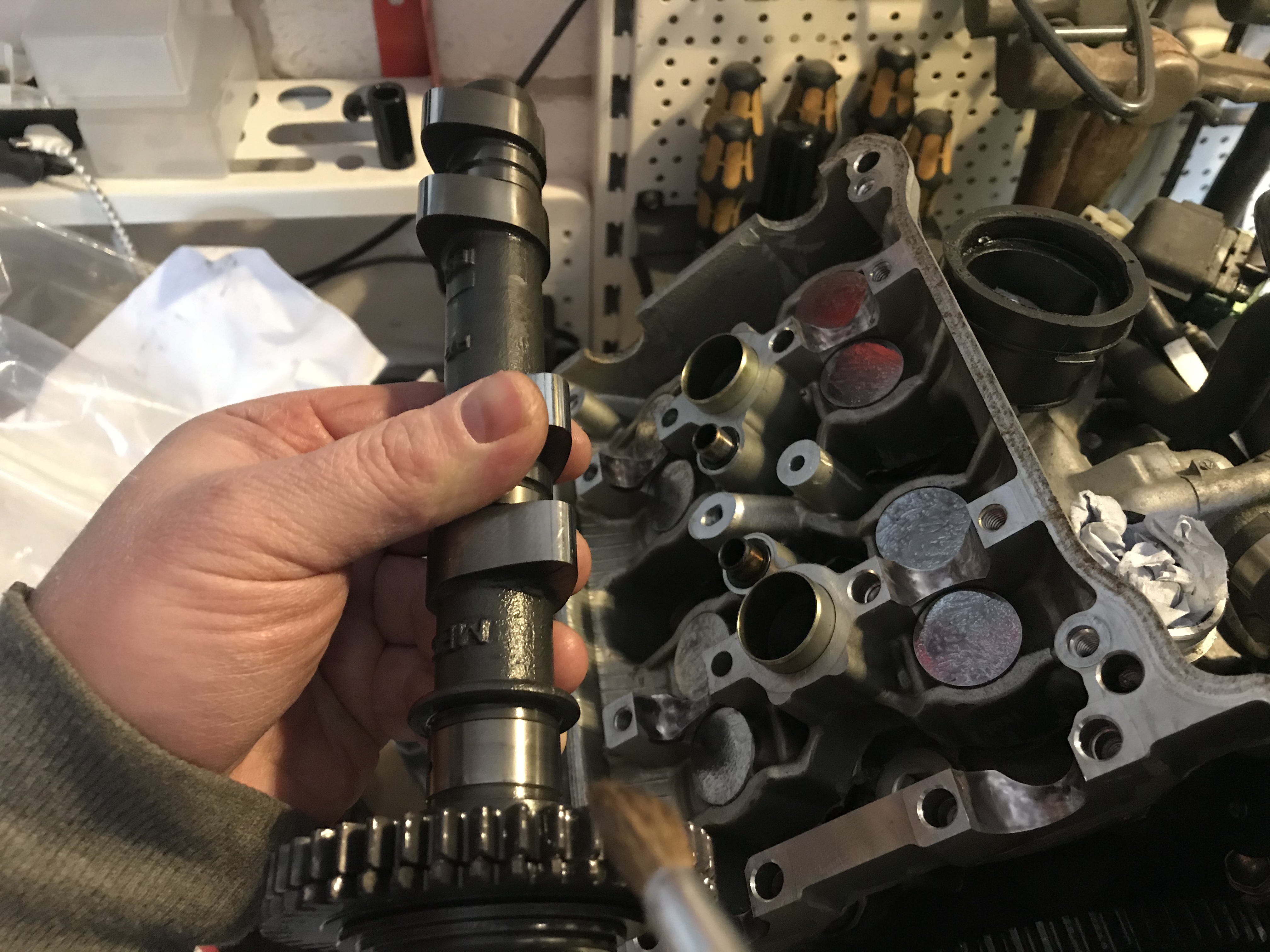
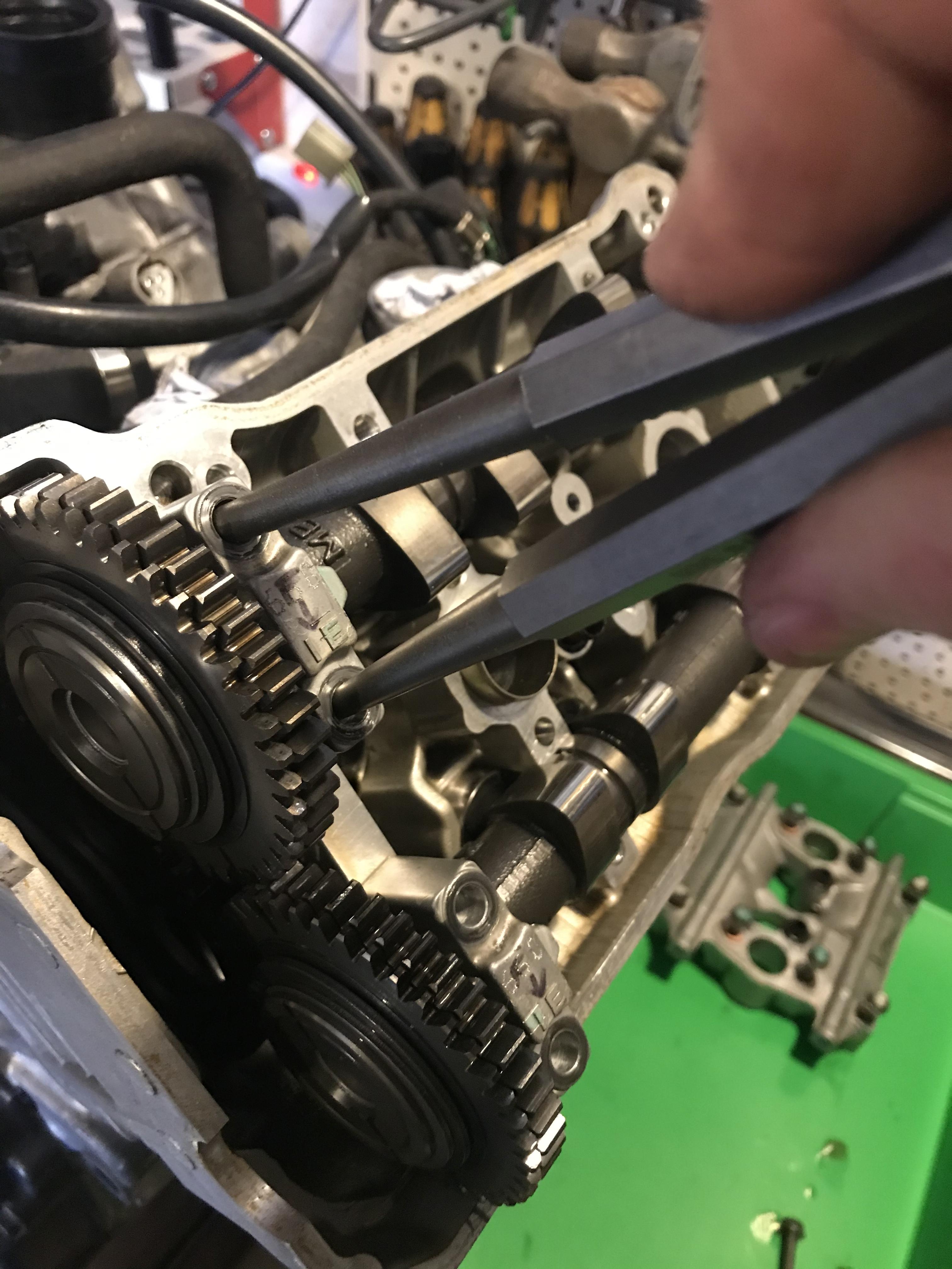
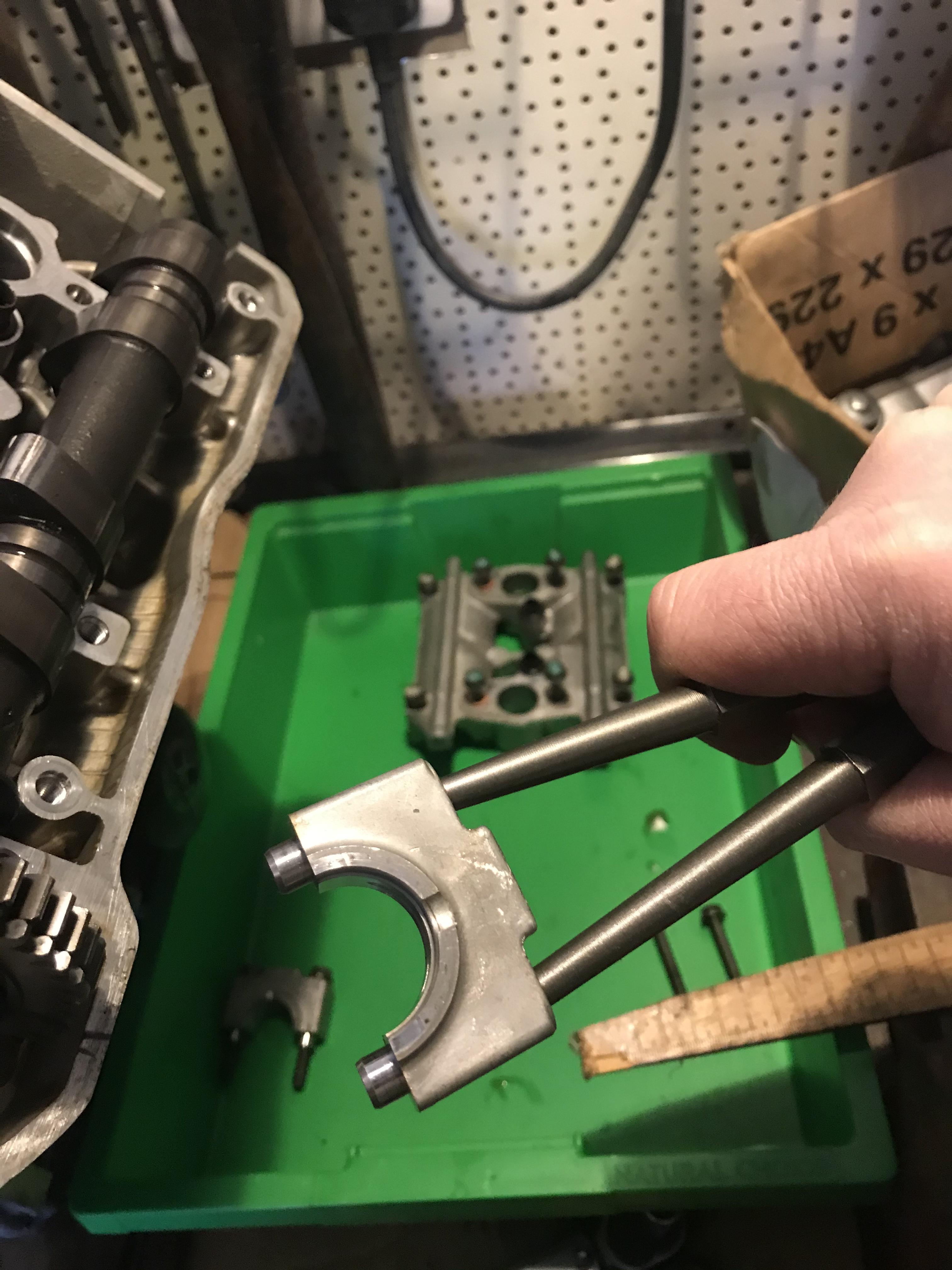
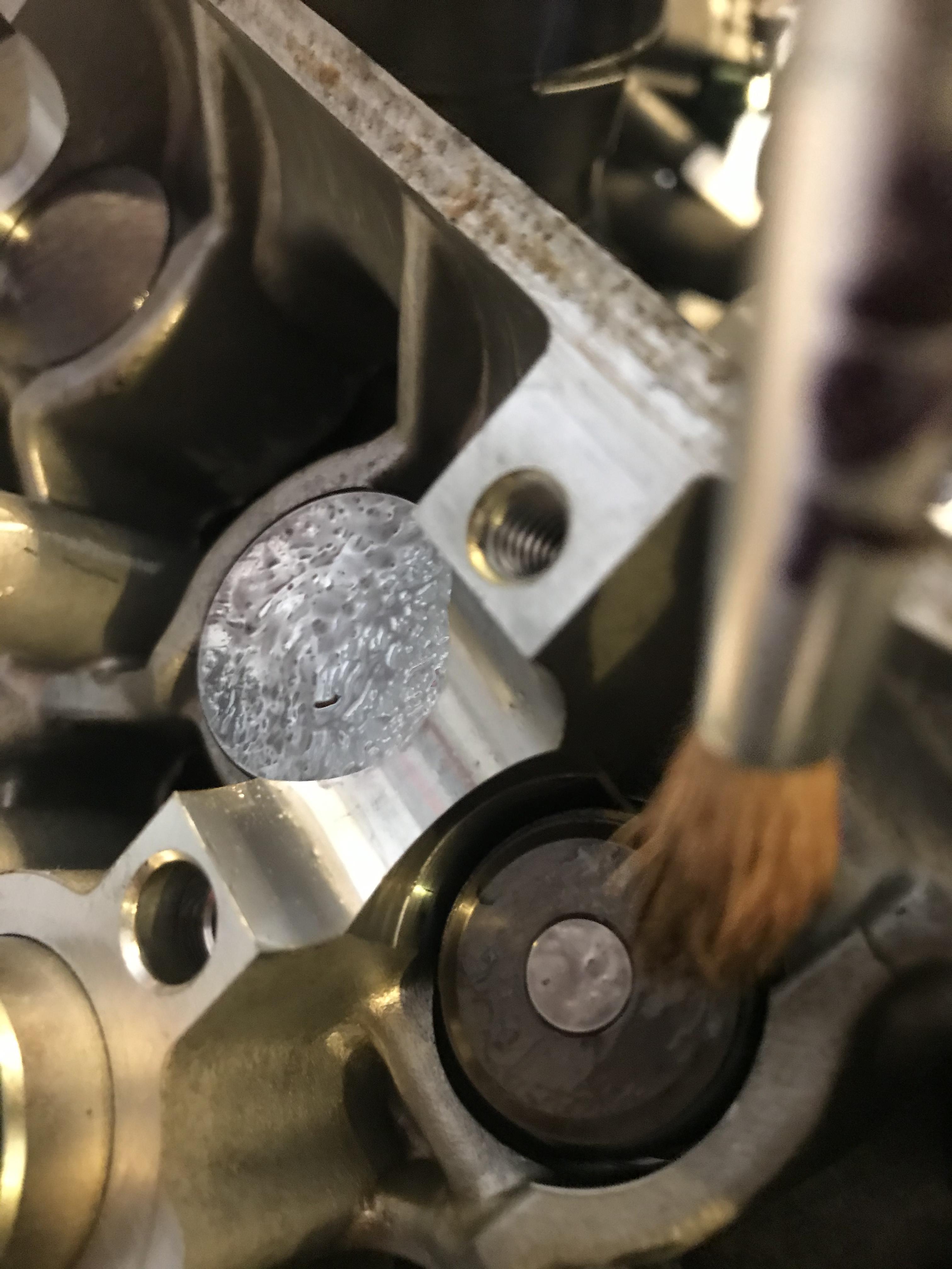
Hello Folks, Got a bit more done today - valve shims adjusted and buttoned up. More on that below. First, an update on some of the engine case markings. The ones that look like they were made by machine match the camshaft clamp numbers inside. Funny how I’ve never noticed before (although my engine has never been clean enough to make them out before!). Markings on outside of cylinder head (facing throttle bodies)... ...matching camshaft clamp. Different code in front and rear cylinders and they both match their respective clamps. Must be paired up at the factory. Also, that “stress cracking” described earlier is all over these engines. Inside and out. Even the cam clamp has some. I opened up one of my scrap engines to harvest the shims and that one had crazing all over too. Must be a casting flaw as Dangeruss says. Anyway, on to the valve adjustment. First thing is to spin the engine with a 14mm socket on the crank until cylinder 1 T mark lines up with the cutout on the clutch cover (no photos of this - sorry!). The gear markings must be facing away from each other and parallel to the cylinder head. If they don’t, spin another 360* until they do. You’ll have to spin the engine separately to measure each cylinder as per the manual. It’s simpler if you go 1, 3, 2 then 4. This helps keep the lobes properly aligned and you can separate the front and rear cylinder heads. Fit the feeler gauges between the cam lobe and shin bucket to measure clearances. Intake is 0.16mm and Exhaust is 0.30mm with a tolerance of 0.03 on both. Any shims out of spec must be removed, measured and replaced with an appropriate size to bring the gap back into spec. With only 10k miles I didn’t expect much to be wrong but there were some that required attention. One of the intake valves in cylinder 3 was on the very edge of spec at 0.13. Here are my notes: Had a few old shims from another engine so I stuck them on a strip of double-sided tape along with micrometer measurement in case they could be reused. Initially, I planned on getting everything exactly in the centre of spec but even with playing “shim shimmy” that was impossible. I’d have to settle for good enough. Once measured the head would need taking apart so the shins can be accessed and swapped. Before undoing any bolts I like to mark the cams with sharpie and a ruler so they can go back in exactly the same way. Also I colour in the teeth where cam gears meet for extra precision. Undo cam holder bolts in a crisis-cross pattern about 1/2 a turn at a time until loose. This helps the clamp rise true and not warp. If the cam clamp binds on one side it can start rising skew - just tickle it with a rubber mallet to keep it flat. If you’re struggling to remove cam gear clamps try sticking some close-fitting tools in the hole so you can wiggle them free. I used some chisels but screwdrivers will do. Just avoid going deep enough to damage the bolt threads. Wiggling and judicious application of a rubber mallet will have it all apart briskly! I like to keep bolts in the same holes just in case there are any minor variations. Best not to mix up your hardware. Good chance to give the PAIR and spark plug dowels a good clean. My o-rings looked OK so they got reused. Now use a magnet to pull out the shim bucket so we can remove the shim under it. Careful: sometimes the shim comes out with the bucket and can roll free. I spent 15 minutes hunting one on the floor and another 15 minutes fishing one out of the engine with the magnet... Here’s the little shim: 7.48mm diameter. Tiny little things! They don’t seem to have a way up as they’re factory fitted with their size markings facing both up and down. I noticed where they meet the valve they develop a small circular wear mark. The side meeting the bucket has a bigger circular wear mark. This, along with minor swirls on the buckets suggests these spin as the camshaft lobes hammer them. Interesting design... Another observation: virtually none of the size markings are exactly right. The micrometer found most markings were wrong - only two on the whole engine were bang on! Here’s an example: shim is marked 182 but micrometer says it’s 183. All measurements finally finished. I was planning to get everything to exact spec (0.16 intake and 0.30 exhaust) but shins are only available in 0.05 increments (or 0.025 from dealer at eye watering prices, so I couldn’t get it bang on no matter what I did. Then I read the KevCarver has had success with sanding his shims to the exact size he needs, so I thought let’s give it a go! Got a piece of flat glass, some worn 400grit wet-and-dry paper, duct take and a drop of dish soap. Experimented on the slightly tight exhaust valve that only needed 5 hundredths of a mm (mm, not inch!) removed. Took measurements before sanding. Was 173... ...and after sanding (now 1725). Sanding is done in a figure 8, measuring every few strokes and turning the admin 90* every now and then to keep the cutting even. Within about 5 mins I’d rubbed off the 5 hundredths and the rubber side was smooooth! But upon inspection of the shim it seems the side I sanded now had chamfered edges and the face was ever so slightly domed where I probably rocked the shim with my finger whilst sanding. Compare the straight reflection on the original face... ...with the slightly domed reflection on the sanded face. See how it’s rounded on the edges? Probably from rocking when rubbed and possibly where water made the sandpaper warp. Very hard to hold these shims flat as they’re so small. Might work better with shims of a bigger diameter (like on my Yamaha) but these are just too small so I decided not to sand any more of the VFR ones. Time to swap the two shims I could service and button everything back up. For this I’d need my own home-made camshaft moonshine to keep things smooth on first startup when there’s no oil. For that we need equal measures of engine oil and WS2 grease, with a pinch of WS2 powder to taste. Similar sort of thing to molly EP grease only slightly more slippery (and a bit more expensive!). All thrown into a sriracha sauce bottle with 3 old bolts to help mix things up. Give the bottle a good shake and let the bolts mix everything together nicely. It’s a homemade engine assembly paste, I suppose. With a bit of luck the WS2 will burnish into the cam lobes and journals to help reduce wear. This special sauce is then dropped on the shims, buckets and most importantly on the cam bearing surfaces. A paintbrush helps achieve good coverage. Also brushed this sauce on the cam gears and cam journals to minimise damage on first startup. At last everything is back in position and properly greased up. With everything in place it pays to spin the motor a few times and recheck valve clearances. On the rear bank I found some of my clearances had shrunk by 0.005. Much swearing ensued!!! Upon inspection I realised my torque wrench was set to 13Nm instead of the specified 12Nm. So I loosened all the bolts and redid them at 12Nm, at which point my clearances were fine again. You MUST use a torque wrench for this procedure as just a bit too much could wear your camshaft bearing surfaces and mess up your valve timing! Hope this helps someone on the same journey. Stray
1 point