Grum
-
Posts
3,821 -
Joined
-
Last visited
-
Days Won
119
Content Type
Forums
Profiles
Gallery
Blogs
Downloads
Events
Everything posted by Grum
-
 I've used this stuff on the lower exhaust on my 8gen. Keeps it nice and shiny. Picture - Lower exhaust after 90,000k's.
-
Very nice work Justin. Looking Great
-
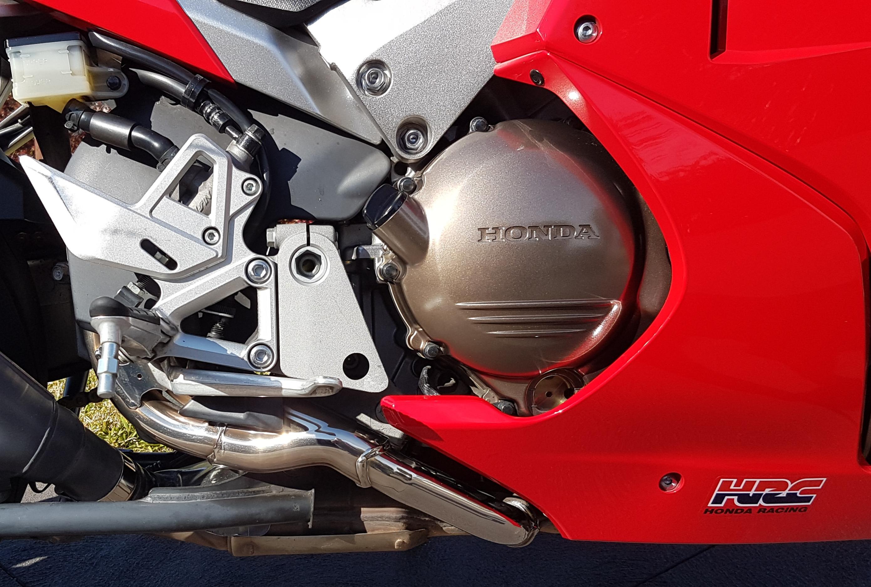
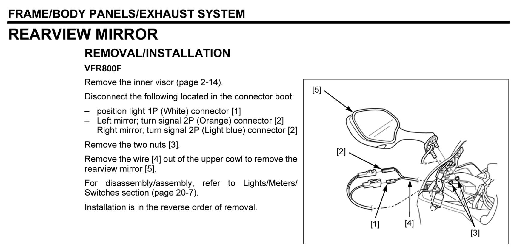
Nothing annoys you more when something like this happens, I feel your pain. Hopefully this helps. Check out Partzilla or Revzilla for parts. R/H Mirror Part No. 88210-MJM-305ZA ($122.82) OR Part No. 88210-MJM-D10ZA supersedes the original, see Revzilla site ($121.50).
-
Things to check...... 1. Check for continuity of the Sensor Body (Ground) back to the Battery Negative Terminal. 2. Make sure the connector to the Sensor is clean and making good contact. 3. Measure 12v between the Sensor wire and Ground, ignition to On. Refer Service Manual. 4. Check continuity of the Sensor wire, from the Sensor up to the Instrument. 5. Check 12v at the Instrument Black/Brown 12v, Green/Black Ground. 6. Check the three connections at the instrument are good and clean. 7. Do the resistance checks for the Sensor. Refer Service Manual. The Service Manual is downloadable from this forum if you don't already have it.
-
Hey Skids. Am I seeing something strange?? Does that look like a broken Wax Unit shaft circled in Red?.
-
Finding things and needing answers
Grum replied to weerab's topic in Third and Fourth Generation VFR's
When in gear, if you lower the Sidestand the engine will shutdown, this is normal and not dependent on the clutch switch. As Terry mentioned. Without the clutch switch you will not be able to do an in gear start with the Sidestand Up and clutch pulled in. It will not crank over. -
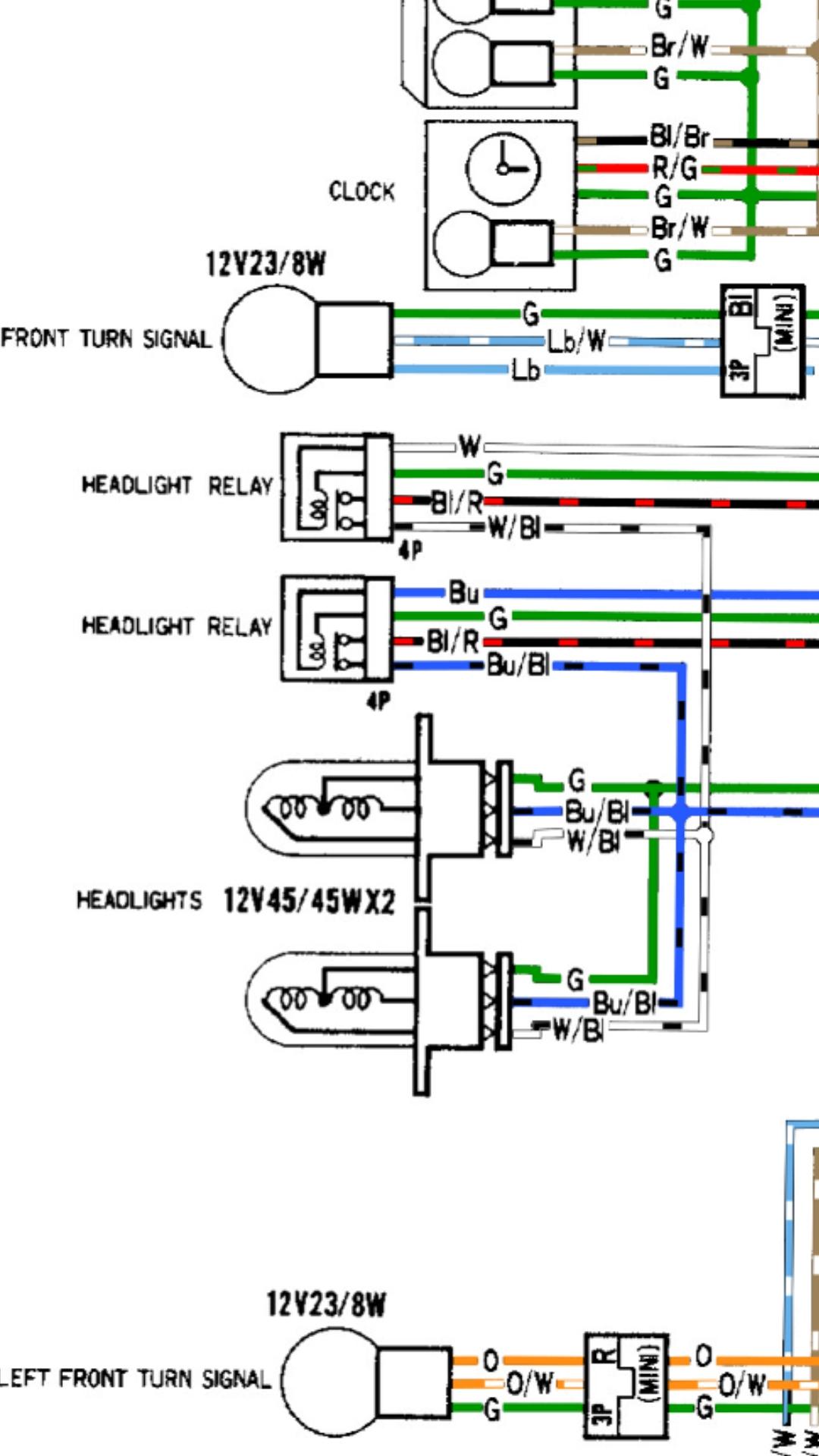
Looking at the 1993 onwards 3rd gen wiring diagram, the Hi and Lo Beam relays are supplying BOTH bulbs at a time Not just one! Are you sure you don't have a blown globe?
-
Rear brake doesn’t work after front pad change
Grum replied to LEGEND's topic in Maintenance Questions
Hi bmart. There's plenty of good graphics in the Service Manual Section 15, it shows all the hydraulic lines and bleed sequence. Hopefully the OP already has the service manual. -
Rear brake doesn’t work after front pad change
Grum replied to LEGEND's topic in Maintenance Questions
Just to be clear, operating the front brake will have no effect on the rear until the Secondary Master Cylinder sees rotation force from the front wheel acting on the SMC. So being on the center stand and spinning the rear wheel the front brake has no effect on the rear. (If my memory serves me well?) The center piston of the left front caliper is operated by the rear brake pedal, and it's bled via the left front caliper center bleed valve, try this and a bleed of the rear caliper via the rear caliper outer bleed valve. Hopefully that will clear any air you may have in the rear system. -
Hi Phil. Don't know if this helps, but have you made sure you meet the minimum requirements as per attached. Your old computer and Sony TV might not meet minimum specs. I had a situation just recently trying to load a Qantas app on my old android Samsung S7 phone, the app was nowhere to be found in the Play Store. Reason being my old S7 was not compatible with the Qantas app, so it wasn't viewable. No problems finding the app and loading it on my fairly new Samsung tablet.
-
That was quick, and the repair was a simple one. Glad it solved the LED issue and didn't cost you a replacement Instrument Panel.
-
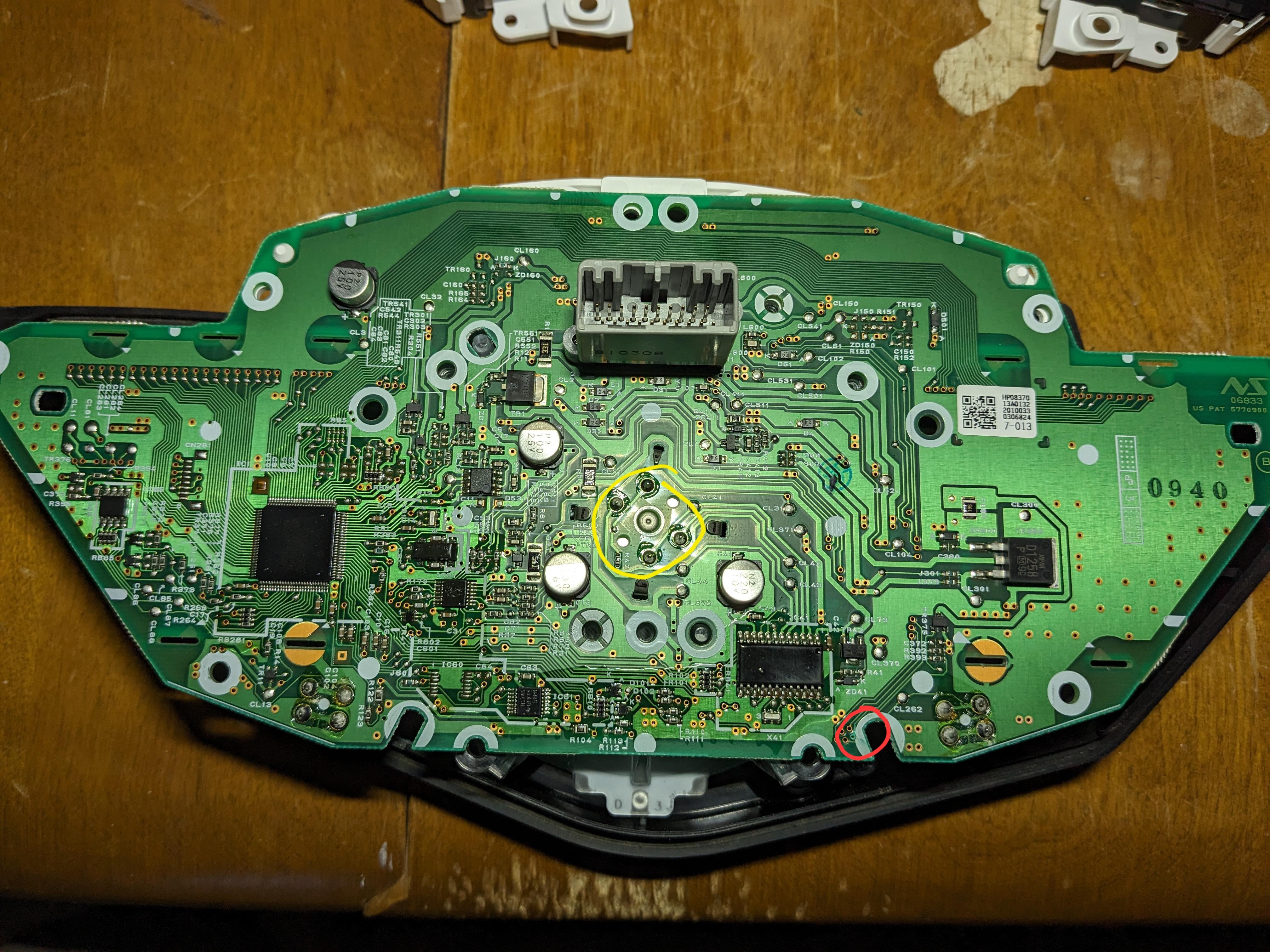
Just for info - To remove the Tacho you might have to de-solder the four connections circled in Yellow and bend back the four black tabs near the solder connections, can't guarantee it, I don't have a 1200 but that’s what I think needs doing provided you have definetly removed all possible mounting screws. Keep us posted, and as mentined, look very closely over the PCB for any other open circuit tracks and signs of corrosion like the one found, it appears any moisture damage is in the lower portion of the PCB.
-
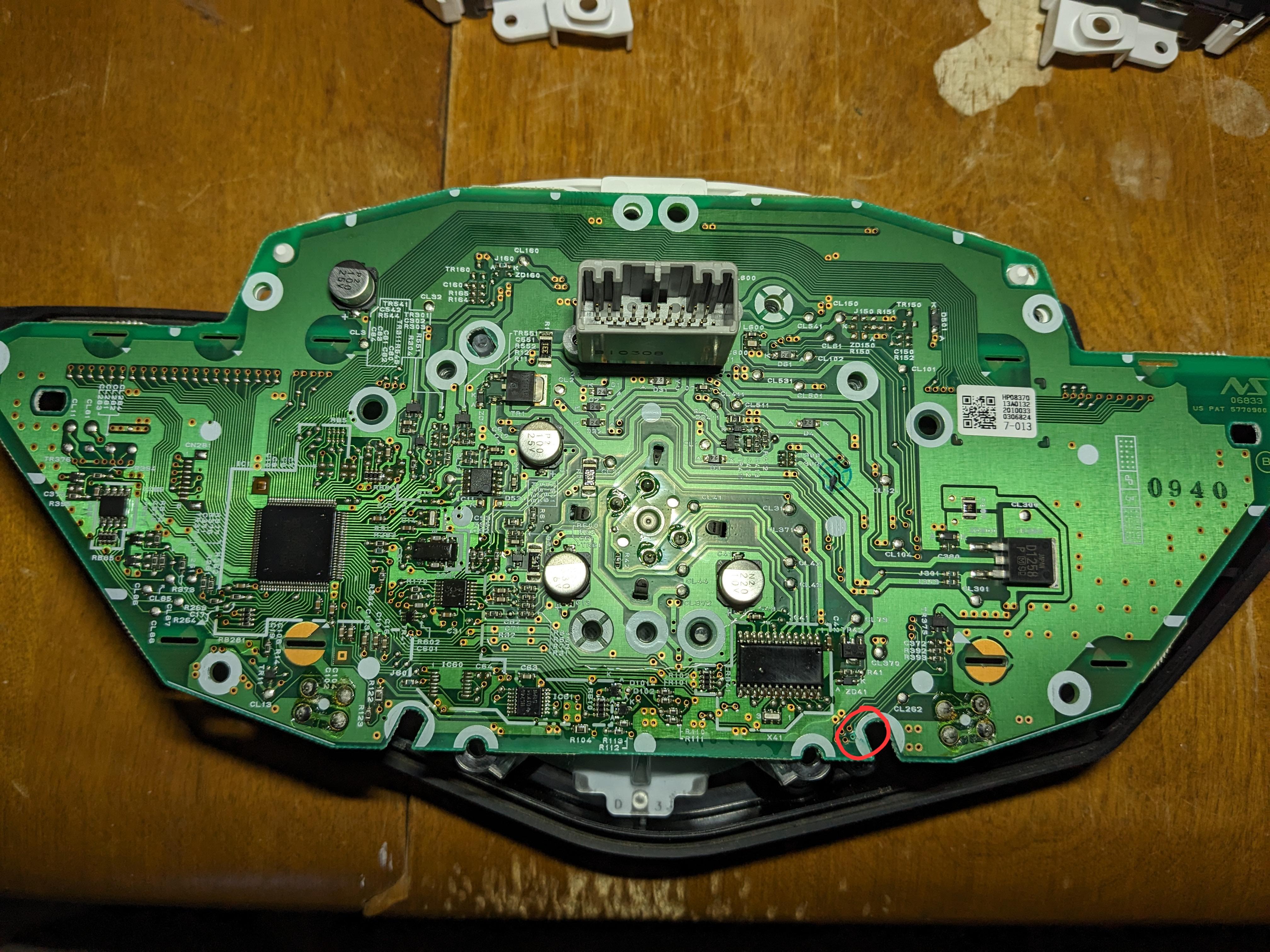
Definitely repairable. The open track that is! You need to very carefully, with a sharp blade, scrap away a small section of the green protective coating to expose the copper of the track. Tin this section with solder then carefully solder a piece of tinned copper wire, (kind of like very small gauge fuse wire you would use in a house prior to the invention of domestic circuit breakers) to the copper track. The other end you want to fit through the eyelet and solder it to the eyelet as well at a convenient spot on the other side of the PCB. Early electronic PCB's used to be of wire wrap technology small gauge single strand wire insulated, wrapped around a connecting post. This type of wire would be ideal if you can get it. Suggest using the straight section of track just opposite and slightly below that CL262 point. And yes probably not best to disturb the solder at R393 however that spot could be used as a last resort. Check your repair with a meter making sure you have continuity from the leg of R393 right through to the eyelet and through to the destination point on the opposite side of the PCB. Be careful and good luck, hopefully that open circuit track might be the cause of your LEDs not working. If you're not confident with the repair. See if you can locate a good Electronics Technician with good soldering skills, he should be able to repair the track for you.
-
So the bottom line is your starting issues were all caused by a bad battery. Is that correct? Or are you saying you have both battery and a starter relay fault? I'm confused.
-
Nice lot of photos Justin. That bolt missing and the tyrap in its place is for the Bank Angle Sensor. Agree, sure is a slack fix, not even neatly cutting off the excess. I wonder if a thin smear of silastic around the panel cracks that you've repaired might also help in keeping moisture out? Keep up the good work, it will be a very special 5gen. Cheers
-
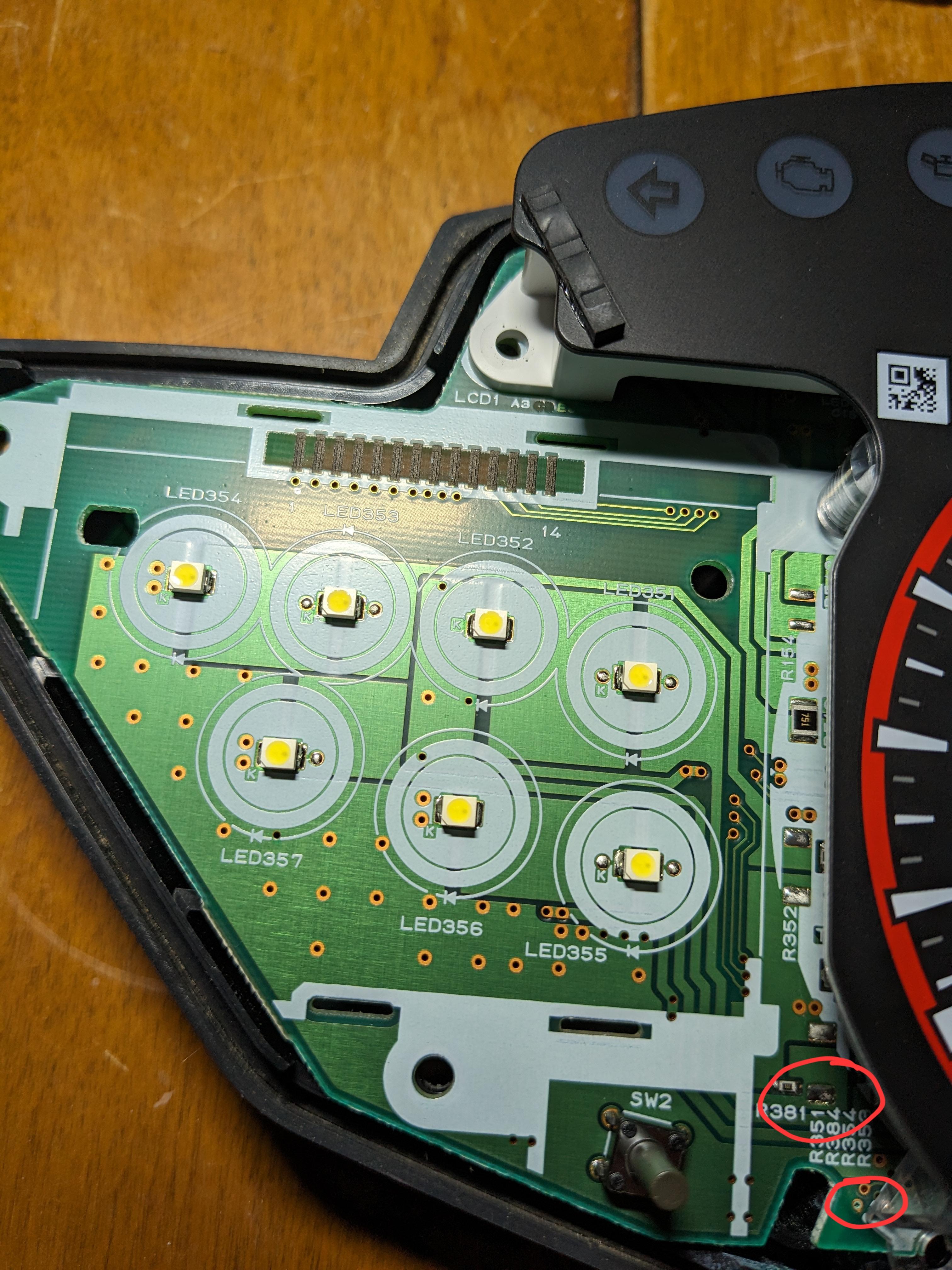
Hi Devorlast. The Service Manual doesn't go into great detail regarding the internals of the Instrument Panel. The Ignition Switched power for the panel comes in on the Black/Brown wire, this is the power that would also feed the LED's. The clock or backup power (always powered) is the White/Green wire. The common Ground wire is the Green/Black wire. Looking at the LED's you'll notice the Cathode side of the LED is clearly identified by the letter K next to it. Hopefully all Cathodes will go to the Ground wire for all LED's. You could confirm this with a multimeter for continuity. The other side of the LED's being the Anodes will most likely end up at a voltage regulator or power transistor possibly converting 12v down to 5v or 3v. See if you can power up the panel and measure the Anode voltage at the LED's with reference to the Ground Green/Black wire. NOTE - All the Transistors on the panel are labeled as TRxxx. If the anode voltage is missing? See if you can track the anode side using your meter on continuity mode to locate the voltage regulator. Once you find this device which is normally a 3 legged device you should measure 12v on one leg, Ground on another and the regulated voltage output on the third leg. You might also find an open circuit copper track caused by the moisture ingress wihen doing the continuity checks. Have a very good close inspection of all the copper tracks checking for any sign of moisture damage or corrosion. Have a good look in the areas I've circled in red, zoom in (you may need to refer to your original higher resolution photos) and notice the greenish moisture corrosion around the eyelet and possible moisture marks on the Black component, and again another eyelet looking greenish with corrosion, lower area of the panel. These are examples you want to look for when dealing with moisture ingress. Hope this helps, best of luck. Let's know how you get on.
-
Great story Justin, thanks for sharing. Welcome home to an old family member, back where it belongs. Enjoy getting it back to good riding state, no wonder your son is a happy chappy. Nice to see the twins together in the garage. Future father son rides will be a joy. Cheers
-
Great looking 5th gen. Gotta be the best color. Such a clean machine, lucky you. Is the odo saying 30 something thousand miles? Welcome to the forum.
-
Nice comments Hingley. Yep, and I freely admit to have learned a lot from the collective experience of many long time members on this forum. As a last bit of info, and you can take it or leave it. If it was my bike, and it's service history is unknown, I wouldn't hesitate in baselining it's maintenance. I'd start afresh and shout it new sprockets and chain, along with all the normal maintenance items, fluids, plugs, air filter, oil and filter etc. I'd also dive into the electrics, solder up all the grounds in the dreaded orange earth block, solder the stator lead wires to the R/R and its output connector, upgrade the R/R if needed and make good the Main Fuse B 30amp fuse holder and wiring. Enjoy your ride. The Yellow 5gen looks GREAT and deserves all the TLC you can give it. Cheers
-
Hi Bmart. I make no reference to the racing scenario, purely general road riding and on average I'm seeing around 36,000 to 38,000k per chain, (22,500 to 23,600 mile). Only ever used high quality Jap chains D.I.D or EK. and riveted Master Link. Cheers
-
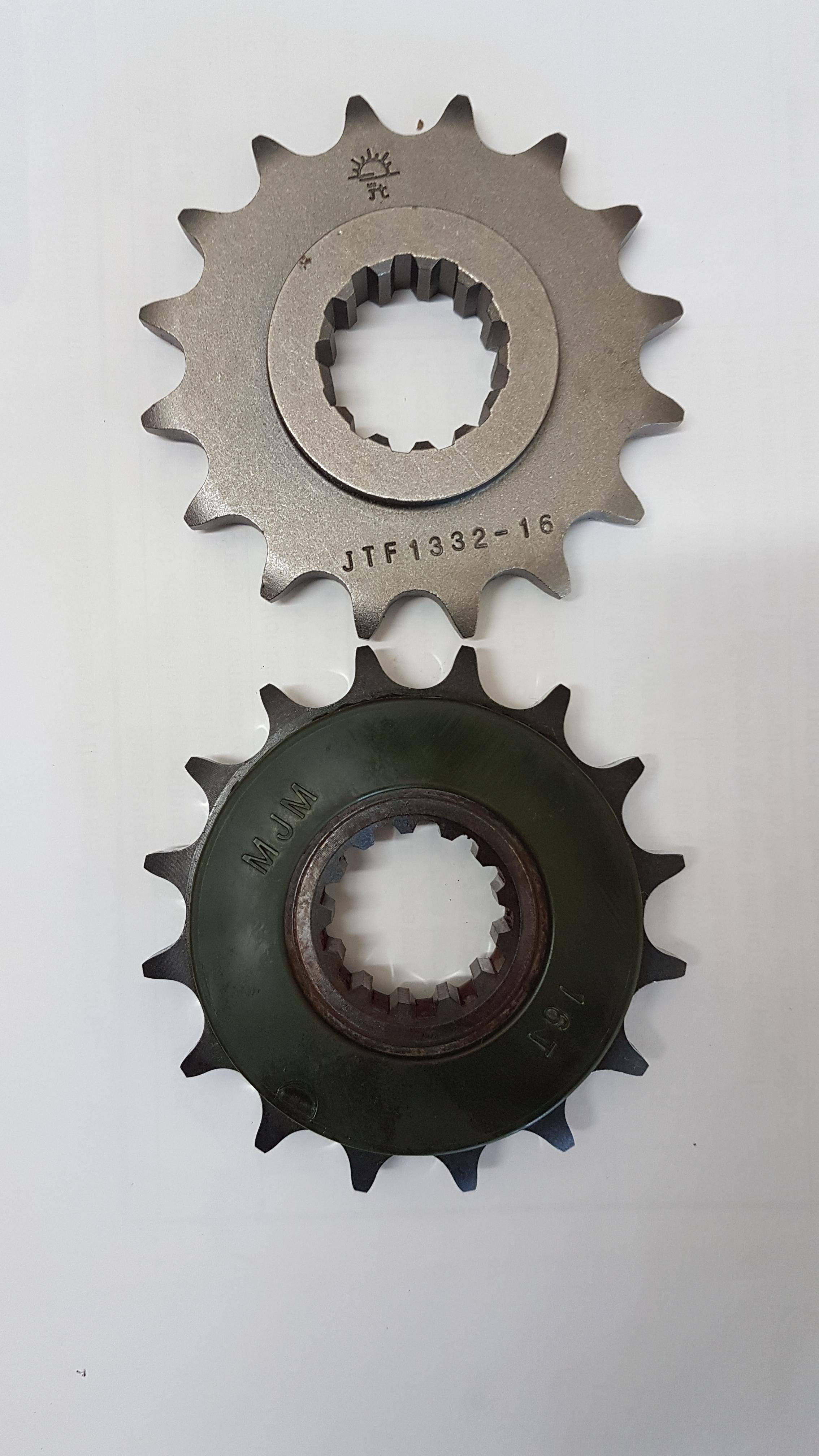
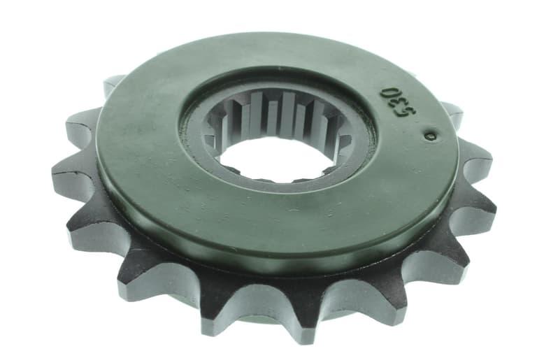
Just for info.... Here's my original 8gen drive sprocket after 74,000 km and the new replacement JT one fitted. (allow for a little Mobile Phone lens distortion, even the new sprocket looks a little non uniform in shape) My current original rear 43T Sprocket has done 96,000 km and has no visible sign of wear! I do have a replacement rear sprocket ready to go for the next chain replacement, but will it really need replacing???? The bottom line here is that always replacing sprockets and chains as a set is old school and a waste of money. Meticulous attention to chain tension and regular Chain/Sprocket lubrication will see good quality sprockets last for ages, particularly the OEM. And as Honda descibes in their Owners Manual, if there's no sign of visible wear, there's no need to replace them. I guess it's also fair to say that riding styles, riding conditions and weather, along with those who unfortunately have to ride on salt laden roads will have a big effect on both chain and sprocket mileage. BUT, As always YMMV.
-
Yep looks like a genuine Honda sprocket to me.
-
Now that you've established the spade connectors on the Relay that go to the coil, you can now do the Function test of the Relay as suggested in my first post!! Again MAKE SURE YOUR BIKE IS IN NEUTRAL. Failing the test and assuming you do have a healthy battery, then go buy a new Starter Relay. If the test passes then you need to establish both Power and Ground for the Starter Relay coil as per the diagram posted. Also no answer from you from previous questions... - Have you confirmed the Neutral Switch is working? Is your Neutral light on? - Have you tried a Sidestand Up, Clutch pulled in start? Good luck.
-
With Ignition on are your headlights glowing normally??? Ohms testing the relay coil is really only of benefit if checking for an open circuit coil. It's easy to functionally check the Relay. But yes you should see zero ohms across the main contacts when energized.
-
Before buying a new Starter Relay! Just be sure that your Battery is definitely in good health as you say it is! And battery terminals are clean and tight. I've also mentioned how you can check the operation of the Starter Relay! When you independently powered the Starter Motor was this from the bikes battery or some other battery? A clicking Starter Relay can be caused by a bad battery.(or poor wiring connections). It might be working but there is no or insufficient battery capacity to run the Starter Motor. So if in doubt charge the battery and have it load checked, any descent auto parts store will do it for you FOC. Or simply monitor the battery voltage as you press the starter button, what does the voltage drop to?