GreginDenver
-
Posts
307 -
Joined
-
Last visited
-
Days Won
7
Content Type
Forums
Profiles
Gallery
Blogs
Downloads
Events
Everything posted by GreginDenver
-
there are two reasons for the resistance you felt in the center piston of the rear brake caliper. one of the two reasons is that your '98 is now 22 years old and I'm betting nobody has ever refurbished the braking system (22 year-old caliper piston seals, 22 year-old caliper piston wiper rings, 22 year-old brake line hoses, 22 year-old master cylinder seals, and, most probably, some really old brake fluid). let's be honest, some parts of a motorcycle are "consumables", like brake pads. but so is the brake fluid and the seals inside the brake master cylinders, the seal inside the secondary master cylinder, and all of those VFR800 rubber brake lines too. if you want to feel the Honda-goodness that Honda had in mind for the brake performance of your 22 year-old VFR800 it's gonna need a full refurbishment at some point. the other reason that the center piston on the rear brake caliper would put up a fight is that on this particular caliper piston there's a lot of mechanical resistance between you (trying to push it in by hand) and the Rear Brake Reservoir (which is where you're trying to make the fluid go with all of your pushing). there's resistance at the PCV, resistance at the SMC, and there's resistance at the Rear Brake Master Cylinder. remember that the brake fluid is incompressible, so it's looking for a space with air (that is compressible) to occupy. the best way to push in caliper pistons is to open the corresponding bleeder fitting on the caliper then push in the piston. if you have somebody handy to help you (one person presses the piston in while the other person carefully/gradually cracks open the bleeder fitting just a tiny bit) it's easy to control the situation and avoid admitting air into the system. yeah, it's a bit messy and if you're not careful you could admit air into the caliper, but it's really the easiest way to do it. and you should probably bleed the brake system every-so-often anyway, right?
-
New 5th/6th/8th gen performance header now in production in USA
GreginDenver replied to sfdownhill's topic in Exhaust Systems
You really don't know what you're talking about. This will probably piss you off, but it's the truth. -
Well, good luck with the bike. Hoping your various maintenance actions will make the odd feeling go away. Sometimes people "solve" problems without ever knowing what the problem was. Having what feels like a cylinder "dropping out" as RPMs climb is a pretty worrying feeling. Based on the VFR800 engine firing order the cylinders that I believe would cause the biggest "feel" if one of them started dropping out would be either #3 or #2 because... ... VFR800 firing order (in 90 degree increments): 1-0-3-0-0-2-0-4- so if either #3 or #2 dropped out you'd get a really long (450 degree) empty space. And the #2 cylinder might be the worst of the two because it dropping would place the 450 degree empty space just before the (signature VFR800 V4 item) cylinder #4 and #1 big-bang combo (only separated by 90 degrees).
-

-
When you get a good deal on a bike that was stored away in the back of a garage for years you have to suspect that there was a reason the bike got relegated to the dark shadows. Now it could be that there's a simple, harmless (not mechanical) reason for the bike getting stored, something like the owner having a near-death experience that scared him so badly he quit riding. But more often than not the case is something mechanical related was making the bike disagreeable, worrying or just not fun to ride any more. People put bikes like that in the back of the garage and ignore them. When you take possession of a bike with this sort of history (i.e., mostly unknown, long stored or highly suspect) you should be willing to give it a good bit of precautionary/refurbishment maintenance. You just have to accept that this "good-deal" bike might require some investment of money, time and effort.
-
I installed a set of Galfer lines on a 2000 5th Gen just three weeks ago. It wasn't my bike. A friend brought the bike and all the parts to my garage (he doesn't have much experience wrenching on bikes). A couple of years ago I installed a set of Spiegler lines on my 1999 5th Gen. We removed all three calipers. Disassembled them for a thorough cleaning. And then we replaced all of the caliper's piston seals and wiper rings (yeah, 20 year old rubber should be replaced). We also removed, cleaned and rebuilt the front brake master cylinder, the clutch master cylinder the rear brake master cylinder and the clutch slave cylinder. We chose not to remove the Secondary Master Cylinder from the Front Left Caliper. And we were very careful not to disturb its original adjustment. Messing with the Secondary Master Cylinder is a bit of a perilous thing, if you get it messed up at all it can cause all sorts of trouble with the bike's rear brake (the Secondary Master Cylinder controls the center piston of the rear brake). We decided that we were doing enough other things with all the removal-disassembly-cleaning-refurbishing plus installation of the new braided stainless steel lines. So, to repeat, we decided to defer cleaning and rebuilding his bike's Secondary Master Cylinder until a later maintenance day when it will be the only thing we're doing. Installing the new set of Galfer lines was easy. Galfer provides a very precise set of step-by-step instructions. If you're any good at following directions the install is easy and logical. This was the easiest, most enjoyable part of the whole day. When the install work is complete, bleeding the brakes is a two-person job. The Honda Service Manual has a (kinda confusing) description of the order in which you are meant to bleed the brakes. The first time you read through these directions you'll end up confused. The second time it will begin to make sense. The third read-through will make enough sense that you'll be able to make a personal set of notes on the proper order. The fourth very careful read-through will be necessary to confirm the order you've written on your personal set of notes. I have a MityVac that I purchased at Harbor Freight. As we moved from one bleeder valve to the next I would put the MityVac suction on it, then I would tell the bike's owner to pull the brake lever in and hold it (or push down on the rear brake pedal and hold it, or pull in the clutch lever and hold it). Then I would open the bleeder for a second to pull brake fluid through the lines. The thing that makes these Honda Linked Brakes so hard to bleed is (duh) because they're linked. You have to keep track of which bleeder is for which caliper pistons. Without doubt the trickiest part is properly bleeding the Secondary Master Cylinder to the Proportional Control Valve (just behind the fuel tank) to the center Rear Caliper piston. You have to hook the MityVac to the correct bleeder on the Rear Caliper and have your helper compress/pump the Secondary Master Cylinder. In my experience it takes at least two full rounds of bleeding all of the bleeders in the correct order to achieve success. And the full job that we did: disassembly, cleaning, replacing rubber parts, re-installing the calipers, installing the new lines and bleeding the brakes took two full days in the garage.
-
I just watched this short video explaining the Triumph 900 "T-Plane" 3-cylinder engine. Near the end of the video there's an on-board-camera clip that gives you a good opportunity to hear the engine rev under hard acceleration. You're not going to believe how much this engine sounds like a VFR800 engine. If you don't want to watch the whole video just skip to 3:10 and listen to how Triumph stole the sound of our VFR800s. https://www.youtube.com/watch?v=Woh023WrZlQ The cylinder firing order of the "T-Plane" engine is almost exactly the same as our VFR800, just without cylinder #4 VFR800 = 1-0-1-0-0-1-0-1- Triumph = 1-0-1-0-0-1-0-0-
-
Bike vs. car in the twisties
GreginDenver replied to TimC's topic in OTHER Motorcycle Talk (non vfr)
Every time I see one of these I'm reminded of the line from the Tom Cruise movie Risky Business, "Who's the U-Boat commander?" -
Honda just wants you to use a high-quality RTV (room-temperature-vulcanizing liquid gasket) in the semi-circles. Locktite makes good stuff. I use a tiny line of RTV along the entire mating between the valve covers and the gaskets when I reinstall the valve covers (after valve clearance check/adjustment) because I once had a leak after doing the work. I was test riding the bike after a valve adjustment and it started leaking oil from the forward cylinder head. I discovered that the engine-generated vacuum pull (on throttle off overrun) had actually pulled part of the valve cover gasket inward and once it (the gasket) was displaced from its normal place it stayed there and oil was freely leaking from the gap. So from then on I've used a thin line of RTV to securely locate the gasket into the valve cover before re-installing on the cylinder head. And I want to be perfectly clear: I don't put anything on the surface between the gasket and the actual cylinder head top.
-
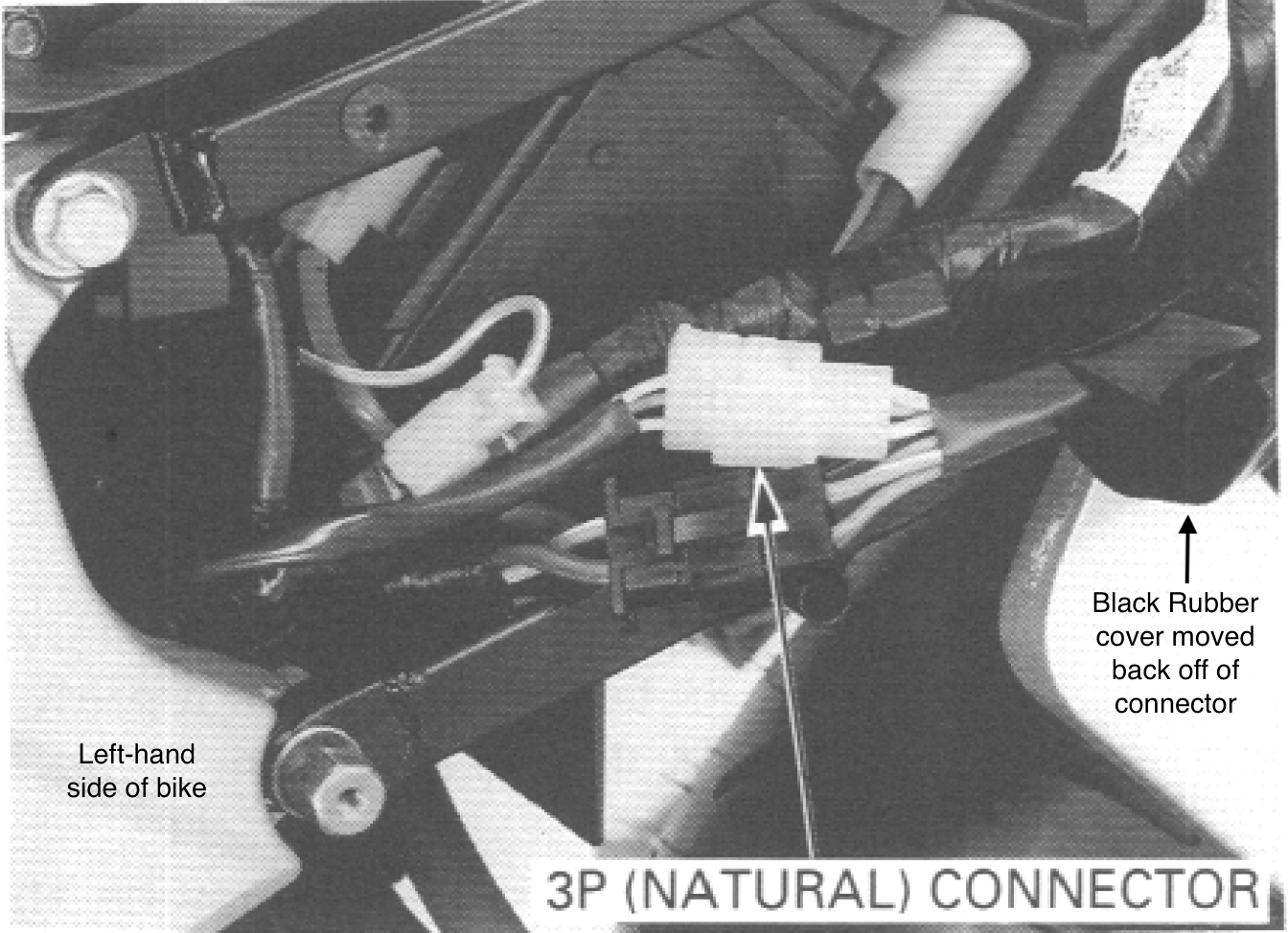
I'm with Grum on this one. It sounds like your bike's charging system is failing. The Regulator/Rectifier on the 5th Gen is a known fail point (it's an old-school Shunt-type Regulator/Rectifier, this type of R/R doesn't last forever, heat issues caused by the shunt-to-ground method of its rectification function eventually kill it). Sometimes the R/R failure is precipitated by corrosion in the multi-plug that connects it to the lines from the alternator stator (this can lead to high temperatures in the plug which will result in a burned/melted appearance). Occasionally it's the stator itself that fails. Either way the R/R ends up compromised and now it won't be able to maintain your battery, which is why it fails during rides. The MAP sensor problem could easily be nothing more than a by-product of worsening situation with your battery and R/R. So, yes, Grum is pointing you in the right direction: Trace the bike's charging wiring looking for connectors that are corroded or have a "burned/partly melted" appearance. If you don't find anything like that you should test the R/R (there are plenty of YouTube videos that can run you through how to do this). Bear in mind that by now your bike's battery may be in poor condition (possibly in need of replacement) you can take it to a shop and have it tested to see if it can still deliver AMPs. It might be that your battery needs to be replaced. It might be that both your battery and your R/R need to be replaced. That's a start...
-
VFR400 tacho does not proper work on mod VF500
GreginDenver replied to RalfR's question in Modification Questions
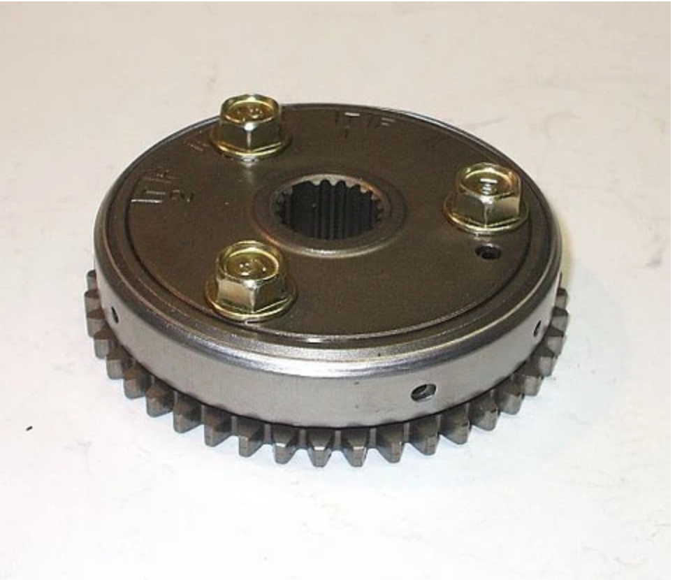
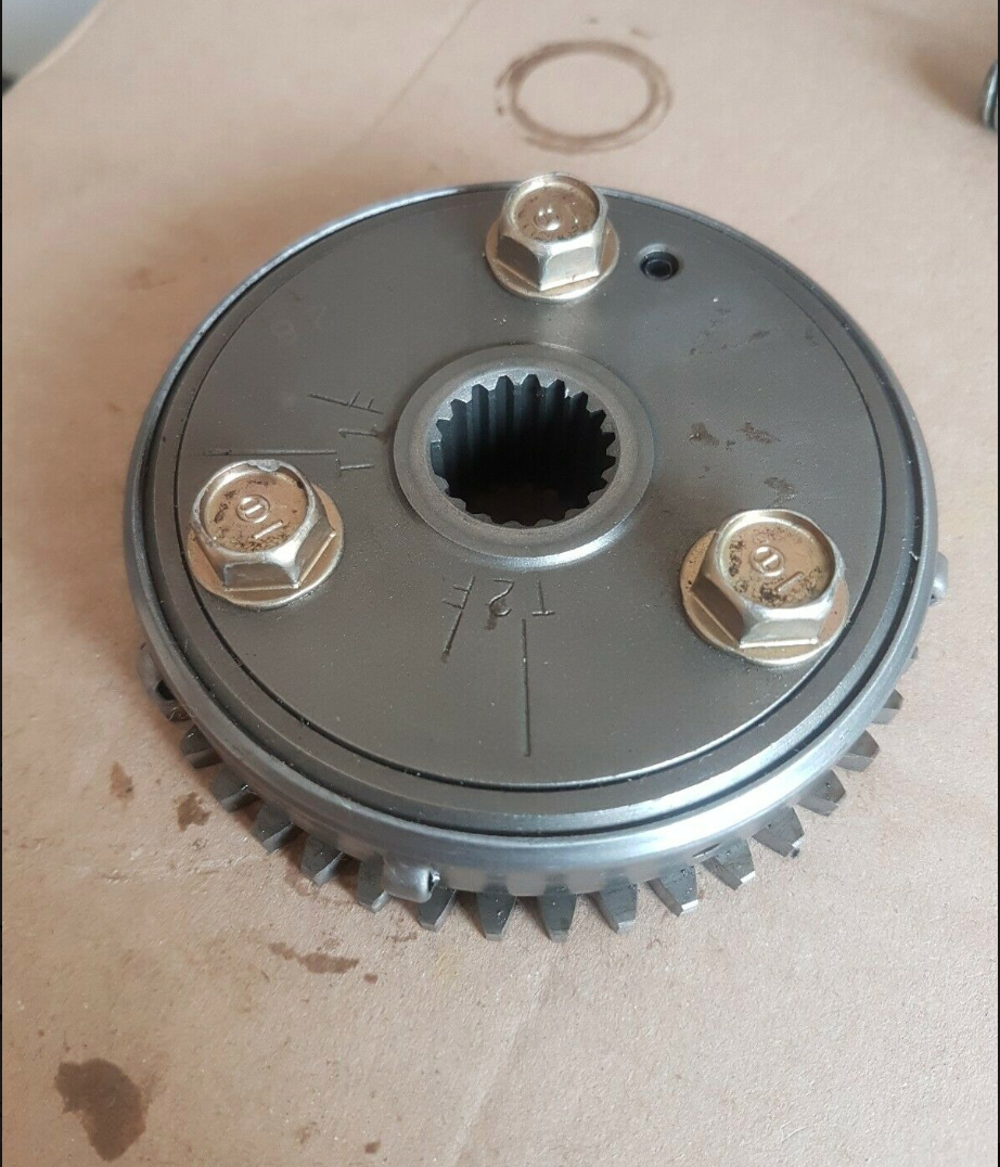
That's an interesting thought. Both bikes have the same crankshaft design, a 360 degree crankshaft. I'm guessing that Honda used camshafts that produced the same "big bang" style order: 1-4-0-0-3-2-0-0- The big question would be: What do the crankshaft trigger wheels look like on the two bikes? Obviously, Honda incorporates the "trigger pattern" into the bike's starter clutch assembly. Because of this your real question is: Can you substitute an NC30 starter clutch onto a VF500F engine? Is there any hope that the starter clutch assemblies of both bikes have identical proportions (diameter, height, etc.) and have identical bolt-on pattern/spacing for the 3 bolts that secure it to the ? And is the Variable Reluctor (Position Sensor) mounted/located in the exact same place on both bikes (so it "senses" the trigger wheel pattern "bumps" at the proper time during crankshaft rotation)? I have to say that from a quick look at pictures of both items they do look like they're very similar. Also, does the NC30 Ignition control Module require any inputs that the VF500F module did not require? For example: I know that some of the more advanced '90s and 2000s carb bikes used a throttle position sensor input to the Ignition Control Module. And I'm going to guess that the NC30 wasn't so advanced that it required a camshaft position sensor, right? (Actually, now that I think a little more about the engine architecture of both bikes I realize that the ignition is probably fired in "wasted spark" mode, which means that the spark plugs inside either head (1 and 3 in the rear head, and 2 and 4 in the front head) both fire on every 360 degree rotation of the crankshaft so there's no need for a camshaft sensor on the engine) But if the "stars and planets line up perfectly" with both bikes having identically engineered clutch sprag wheels with identical bolt patterns and an identical placement/location of the Variable Reluctor pickup (position sensor) and no other mitigating conditions (like requirements for Ignition Control Module inputs that the VF500F did not provide)... Then you're off to the races and it'll be just a question of matching up the necessary wiring to achieve success.
-
Ducati fan fixes the VFR forum. A sign of the coming apocalypse?
-
VFR400 tacho does not proper work on mod VF500
GreginDenver replied to RalfR's question in Modification Questions
After looking at the traces on the backside and seeing how the components are placed on them I've learned a bit. On this VF500F tachometer circuit board it's obvious that the input wire from the Ignition Control Module is used as nothing more than an input to the Integrated Chip, it only connects to the long black item labeled "I" in the middle of the circuit board after going through the 1.7K ohm resistor. The 12volt connection wire is what's metered through to the galvanometer based on the frequency of the Ignition Control Module wire. Will be interesting to see if the NC30 tachometer circuit board runs the same sort of setup. If it does use the same setup the only problem will be getting either: 1. a matching the voltage that an NC30 Ignition Control Module would put on the input line or, 2. If the VF500F and NC30 input line voltages are close together, simply change the resistor it's connected through in order to put through the proper voltage to the Integrated Chip. -
Water Pumps are wonderful things because they don't keep secrets. The water pump has 2 seals inside of it (located on the impeller shaft): one seal prevents the crankcase oil from leaking out and the other seal prevents the coolant from leaking out. The only one of these 2 seals that ever fails is the coolant-side seal. And when the coolant-side shaft seal fails it always does it very slowly and gently. And it gives you lots of warnings that it is planning to check out sometime in the future. When the coolant-side shaft seal begins to fail it will only "weep" out a drop of coolant at a time, and it will only do this while you're riding because the coolant system is only pressurized while the engine is running at operating temperatures. When you stop riding and the engine cools off the coolant system pressure goes down to zero and the "weeping" of the coolant-side shaft seal will stop until the next time you ride. You can go like this for a long time, losing only a little coolant each time you ride. If you're not bothered by the dried coolant stains along the lower left-hand side of the engine and on the fairing and the few drops of coolant on the garage floor. Of course you can't go like this forever. Once the seal starts "weeping" it is on its way (long term) to real leaking, so eventually, if you ignored it might put you in a stranded-on-the-roadside situation.
-
With regard to fuel injection Fuel Pumps: The answer is "you don't know" (caveat: unless you actually hook up a fuel injection system test rig to verify pump pressure, which nobody ever does). The truth about the fuel pump that supplies a fuel injection system is that it is designed (specified by the engineers) to run at more than the required system pressure. The fuel pressure regulator installed in the system is the item that is used to guarantee correct fuel pressure arrives at the fuel injectors. The reason that the fuel pump is built (design specified) to deliver a higher-than-necessary pressure is it's a known fact that over time the internal parts of the fuel pump will wear, original tolerances (inside the pump's electric motor for instance) will widen a bit or get sloppy or have more mechanical drag, and as a result the output pressure will fall. This means that at some point you may end up with a fuel pump that is just barely meeting the required pressure for the system (i.e. the fuel pressure regulator really isn't "calling the shot" any more because there's no excess system pressure to "regulate"). Or worse, your fuel pump's ability to generate pressure drops below the required system pressure for the engine's needs. How would you know? (without hooking the pump up to a fuel injection pressure test rig)
-
VFR400 tacho does not proper work on mod VF500
GreginDenver replied to RalfR's question in Modification Questions
Thanks Grum, now that you say it I can easily see the "V" in "VR1" in the picture. I was thinking there would have to be a potentiometer included in this circuit board as there would be the need to do a bench-calibration of the completely assembled tachometer circuit board. This post-assembly calibration would be necessary for quality control (with pass-fail evaluation criteria) and a fine-tuning calibration effect for the circuit boards that fall within the "pass" level of quality control. This would compensate for small variations in the resistors, capacitors and such. I can imagine the technician, sitting there with a pile of these circuit boards, hooking one-after-another into to a purpose-built bench testing unit that puts a set of controlled inputs into the circuit board and shows the results on something like an oscilloscope and/or voltage meter. -
VFR400 tacho does not proper work on mod VF500
GreginDenver replied to RalfR's question in Modification Questions
I'm looking at that "R1" resistor and I can't tell which end is the gold band, so I can't tell which direction to read the colors, in the picture it isn't quite in focus and has some glare on it. But if I read it right-to-left I get brown-violet-red-gold = 1.7kohms or if I read it left to right I get brown-red-violet-gold = 120Mohms. So I'm guessing the gold band is at the left-hand end. It would be informative to see the connecting traces on the back side of this circuit board. I'm assuming the circuit board is probably a single-layer, but maybe a 2-layer board. Is it possible to get a picture of the backside, or short of that maybe you could draw/diagram out what you see on the backside? And what is the letter designation above the kinda transparent-looking item above R3? I can guess the function of most of the other components but that one is a mystery to me. And I'm guessing that the red and black wires at the left-hand side of the circuit board are marked M+ and M- (can't see the "-" below the lower M, but guessing it's there)? Do these wires lead to and from the galvanometer (i.e. electromagnet) portion of the gauge? And are they the only two wires that go there? But yeah, very interesting just in this one picture. For instance the resistor that is banded red-black-black-gold (I think it's marked "R5") is a 40 Ohm resistor which would be perfect for the job of reducing 12volt to 3volt in an application that is pulling about .25 amps. -
VFR400 tacho does not proper work on mod VF500
GreginDenver replied to RalfR's question in Modification Questions
It would certainly be a great start if you could see exactly what the Ignition Control Module (on both bikes) is doing. Obviously the Ignition Control Module output to the tachometer will be a square wave, a simple on-off-on-off, zero volts-then up to "X" number of volts, then back to zero, then again... Nothing tricky about that. The interesting questions to answer will be: what is the amplitude (the voltage) of the square wave, is it just plain old 12volts or is it something else like 5volts or 3volts? and what is the duration of the square wave (is the Ignition Control Module output to the tachometer the same exact period of milliseconds across the entire rev-range of the engine, or does it vary in length because it's paired up with something like the Ignition Control Module's pre-programmed spark dwell period)? And as you mentioned, there's a question of: Does the Ignition Control Module send just 1 square wave pulse to the tachometer per 360 degrees of engine rotation, or is it sending 2 (or even 4, I think 4 would be unlikely, but 2 is possible)? And, yeah, I understand about having limited electronics knowledge, I'm in the same boat there. But there's a lot of what-if questions you can pose without knowing the exact electrical principles or "best practices". Then you find somebody who does know all of that and they can steer the situation from there. There are also ways you can "get around" the electronic education/knowledge needed to conceive and construct complex circuitry... This whole thing could be as simple as: Get an Arduino Nano, solder on wires for power and ground, solder on the input wire from the bike's Ignition Control Module, and solder on an output wire to the Tachometer. Then write up a very simple operating program for the Nano that says: every time you get a voltage input from the Ignition Control Module you will output "X" voltage on your output line to the Tachometer. Then you could incrementally raise that output voltage until you get a tachometer sweep-needle result that is properly calibrated to actual engine RPM. Or if the voltages are the same (for both the VF500F and the NC30 tachometer signal) but the duration of the square wave is different (either longer or shorter) you could command the Nano to change that duration of signal. This solution could be used to tailor/correct either of the two most probable differences between the VF500F and the NC30 Ignition Control signals: either the two signals are of different voltage, or the signals are of the same voltage but the square wave is of different durations. With data gathered from an oscilloscope you could correct either of these situations. -
VFR400 tacho does not proper work on mod VF500
GreginDenver replied to RalfR's question in Modification Questions
I'm interested in your tachometer swap problem. I think you've got lots of room for experimentation here. These old-school motorcycle tachometers are always just a "galvanometer", which is a gauge that uses electrical inputs to induce an electromagnetic "pull" against a factory-calibrated spring. And the tachometer's face-sweep needle is connected to this. On Honda motorcycles it seems that their normal approach is to give the tachometer a positive input from the Ignition Module (12 volts, intermittent signal that is matched to crankshaft speed). The only other connection the galvanometer-type tachometer needs is a Negative (ground) wire. So, to recap, the Honda method: Intermittent 12 volt (positive) input, constant Negative (ground) connection. Most other older motorcycles that I've worked on (that use this standard galvanometer-type tachometer) do it opposite of the Honda way. My older Suzuki and Kawasaki use a constant 12 volt connection, and an intermittent path-to-ground by way of one of the coils (which means that every time the Ignition Control Module grounds that coil to charge it to saturation the tachometer's galvanometer will flow electrons through its electromagnet, which pulls the needle against the factory-calibrated return spring). But either way you choose to do the positive and negative, it really doesn't matter. All that matters is getting the correct amount of 12 volt power flow through the tachometer to register a correct needle indication. One place to start out in exploring this situation would be to check what the voltage output is on the wire from your VF500F Ignition Control Module to the tachometer. Maybe you'll find something like: The VF500F Ignition Control Module puts 5volt power down that line to the tachometer. If the NC30's Ignition Control Module puts 12volt power on that line to the tachometer, then there you have an explanation for the low RPM reading on the swapped-in NC30 tachometer. But, what If it turns out that the Ignition Control Modules on both of these motorcycles use 12volt power on that line to the tachometer? In this case it might be true that the VF500F module produces a shorter 12volt pulse than the NC30 module does. An oscilloscope can show you the length of the square-wave pulse (I know not everyone has access to this sort of equipment). I'd say the next thing to look at would be the circuitry inside the tachometers (both the old VF500F tachometer and the new NC30 tachometer). You'll probably find that both tachometers have a resistor installed on the line coming in from the Ignition Control Module. It would be possible to de-solder and replace the resistor on the NC-30 tachometer with a lower-value resistor to let more voltage through which would swing the galvanometer's electromagnet more vigorously. You could try different resistors until the correct value was discovered for accurate tachometer readings. People who know more about electronics than I do can help if you explain this situation to them. -
What's the status of your airbox? Did you (or a prior owner) do a "de-snorkel and flapper valve" modification? If your bike is missing its snorkel and its airbox flapper has been disabled I can easily imaging you might get a flat spot in the RPM range you described.
-
Actually there's an all-in-one fuel pump solution that's available from Honda. It's a self-contained external (as in: not an in-tank pump) that Honda uses on its fuel injected TRX 4-wheel ATVs and on their big V-twin cruiser bikes. It's an aluminum housing that includes an electric fuel pump, a 43psi fuel regulator and a "sock" type fuel filter. There are two versions of this fuel pump, one is for engines up to about 550cc and the other is for engines up to 1300cc (the big VTX 1300 cruiser bike). The two versions are externally identical, just the pump volume is different. I used the lower volume version on both of my EFI project bikes, one is 250cc bike while the other is a 400cc bike.
-
And... and... and... and... When you add the MicroSquirt ECU you can also implement full ignition control, which allows you to custom tune the timing and dwell of the ignition coils. The OEM Honda ignition settings are really on the conservative side, there's more ignition advance that can be tuned into the bike without hurting anything. I installed "stick coil" (coil-on-plug) ignition on my EFI project bikes. The DENSO corp stick coils that Honda used on the CBR600RR were perfect for my projects.
-
Exactly what would those problems be? I can tell you that both of my carb-to-EFI motorcycles run better than they did on carbs. The best thing about my EFI converted bikes is that I can let them sit for months and they start right up (I've let them sit through a full winter with no more effort than hooking up a battery tender). I'm not saying that carbs aren't a fine solution for fuel delivery, they are fine. But some people just want to tinker and experiment and improve things, they like to have a project to work on. That was me. I didn't enjoy cleaning and rebuilding and tuning carbs, but I really like the challenge of configuring and installing and running a fuel injection system (tuning air/fuel ratios as I ride the bike around with a laptop computer hooked up to the MicroSquirt ECU). If you've got the necessary skills/knowledge/time/tools a project like this is a very fun and satisfying thing.
-
I've done two motorcycle carb to EFI conversions, a Kawasaki EX250 and a Suzuki GSF400. On both bikes I used the MicroSquirt V3 ECU. If I was doing an EFI conversion on a bike like the VFR750 with its unusual "V" configuration I would convert the original carb set into throttle bodies (which is what I did on my Suzuki GSF400 conversion project). The reason for doing this (instead of trying to engineer up a custom set of 4 throttle bodies into a functional "V" configuration) is that getting things like the throttle actuation linkage rigged to work properly and reliably (meaning: getting the linkage to simultaneously open all four of the "V" configured throttle bodies the exact same amount when you twist the throttle) is really, really difficult.
-
Thermostat replacement - hope to never do this again
GreginDenver replied to 8200rpm's topic in Fifth Generation VFR's
Very nice job. This is going to be a solid 5th Gen, ready for another 20 years.