ggathagan
-
Posts
302 -
Joined
-
Last visited
-
Days Won
1
Content Type
Forums
Profiles
Gallery
Blogs
Downloads
Events
Everything posted by ggathagan
-
From the album: Mirror mounts
-
I'd looked briefly at replacing the single filament socket with a dual filament version. The two main concerns: Finding the proper socket for the bulb. The locking bulb socket that Emgo uses looks pretty generic, so there's a pretty good chance you could find a replacement piece that was made for a dual filament bulb and would lock properly in the lens. The wiring is a more difficult hurdle. The passageway that runs through the stalk of the mirror and the hole that DB drilled through the large Phillips-head screw would both have to be enlarged to allow for a third wire. That would involve a complete dis-assembly of the mirror and make a very labor-intensive process even more so. All in all, I think that my relay scenario involves the least amount of work. After soldering the wire leads coming off the relay, those connections could be covered with heat-shrink tubing and the relay itself could be attached to the inside of the front fairing with double-stick tape somewhere near the existing turn signal lights. You would want to terminate the leads from the mirrors with the same sort of 2-conductor disconnects used elsewhere on the bike to allow the mirrors to be removed.
-
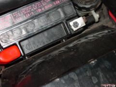
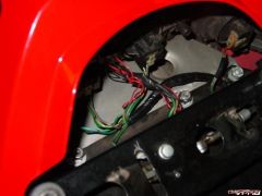
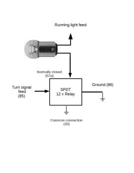
No, 30 is ground and no diodes are needed. 87a is the power lead from the running light circuit. 30 is the path to ground for that circuit (the mirror's bulb). 85 is the power lead from the turn signal circuit. 86 is the path to ground for the turn signal circuit. Instead of attempting to run the mirror's single filament bulb with two different 12v sources (running light and turn signal), my circuit is interrupting the steady state running light source by opening up that circuit's path to ground for the mirror's bulb. Attaching the turn signal lead to one side of the the relay's coil (85) and the other side of the coil to ground (86) causes it to open the relay's normally closed contact(87a) at the rate of the turn signal's "blinking".. Going by the service manual's wiring diagram, Right side connections off of the existing bulb socket: Light blue/White - turn signal - connect to 85 on relay Light blue - running light - connect to 87a on relay Green - ground - connect to both 30 and 86 on relay Left side connections: Orange/White - turn signal - connect to 85 on relay Orange - running light - connect to 87a on relay Green - ground - connect to both 30 and 86 on relay
-
I'm unsure where we disagree. That's the safety function I allude to. The diodes do nothing for the subject being discussed; trying to make a single filament bulb function as a dual filament bulb.
-
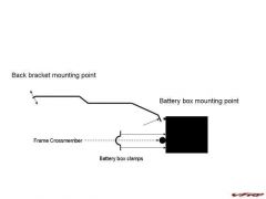
The diodes serve well as a safety function, but do little else. If there is voltage present on either the running light feed or the turn signal feed, the bulb will be lit. Having voltage from both connections simultaneously will not brighten the bulb enough to be of any use. So, it's not a matter of providing two different signals. Rather, you wire the mirror as a running light, then use the turn signal feed to activate a relay which lifts ground for that bulb. You'd want it set up something like this, using a 12 v single pole dual throw relay: The numbers are the connections on a standard relay. 85/86 are the coil connections,
-
From the album: Misc
-
Very nice! Looking forward to the build details.
-
They have. Holeshot has sold their variation for years: http://www.holeshot.com/old/v4/v4_oiler.html
-
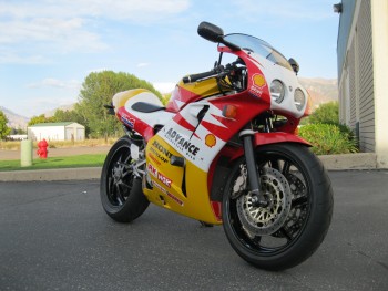
Gorgeous work, Andy! I like the color a lot. Did you ever consider going with a highmount exhaust?
-
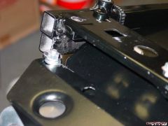
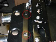
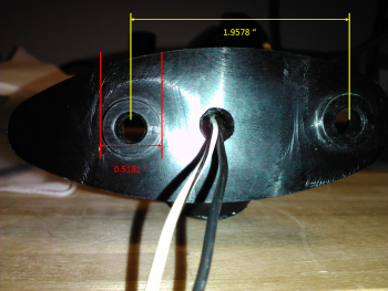
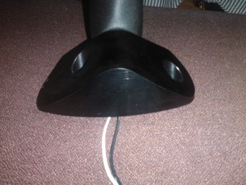
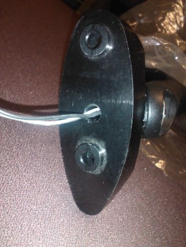
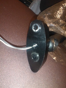
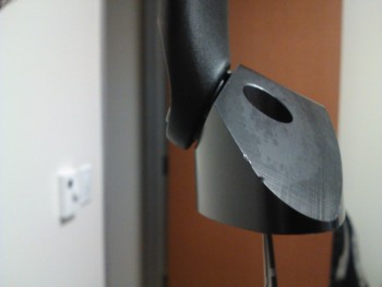
Gentlemen, My apologies in the delay on getting back to this. Life/work has this irritating tendency of intruding... I've added a gallery for the pictures I took: http://www.vfrdiscussion.com/forum/index.php/gallery/album/7119-mirror-mounts/ I have no precision measuring equipment at hand, but the dimensions are along the following lines: Length at the base: between 3 1/2 and 3 5/8 inches Overall height from the base to the highest part of the adapter is 1 1/4". Other than the spacing and diameter of the mounting holes, I think every other dimension would be up to the designer. The trickiest part would be drilling through the large Phillips-head mounting bolt to route the wiring.
-
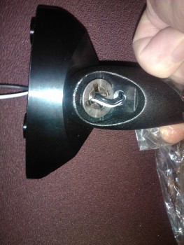
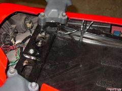
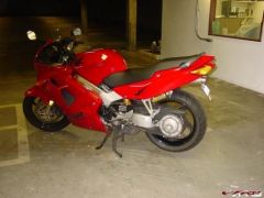
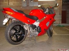
From the album: Mirror mounts
-
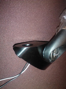
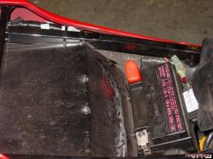
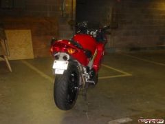
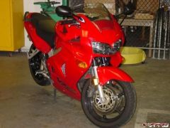
From the album: Mirror mounts
-
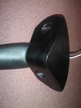
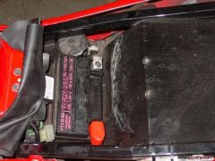
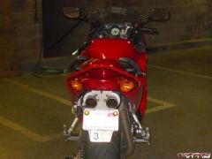
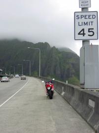
From the album: Mirror mounts
-
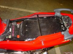
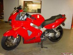
From the album: Mirror mounts
-
From the album: Mirror mounts
-
From the album: Mirror mounts
-
From the album: Mirror mounts
-
Sorry, they're going on the bike at some point; probably when I get sick of looking at the spots on the stock mirrors where the black coating has come off. Ugh... I got caught in all that snow and low temps and didn't get back home until Saturday night. I'll pull out the mirrors later tonight.
-
I have the set that Darth was selling and they are not on the bike. If you can wait until I am back home from traveling, on January 8, I can help.
-
There is a guide for a 5th gen: http://www.vfrdiscussion.com/forum/index.php/topic/6970-how-to-install-an-ohlins-shock/ I don't believe there is a significant difference between 5th and 6th gen for the shock, but I'm not 100% certain of that.
-
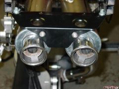
Custom Devil Dual Underseat Exhaust System
ggathagan replied to Veefer800Canuck's topic in Exhaust Systems
One of the things I wish was different on my underseat exhaust is the profile of the up pipe in the section immediately in front of the rear wheel. I don't know if it's feasible to do, but if a fabricator could bend/pound the up pipe into an oval profile in that section, it would go a long way towards solving cleareance problems, particularly with huggers. -
 Very nice!!
 -
CENTER STAND + GSX-R MIRRORS + LED LIGHTS
ggathagan replied to PanzerAstridBears's topic in Modifications
Send a PM to Darth Bling. He made a kit for a number of us with the mirrors and adapters: http://www.vfrdiscus...ors-on-6th-gen/ It's been a while, but he may still be able to set you up. -
You'll note that more than just the forks are involved with these swaps. ABS cannot be preserved for the same reason as the requirement to get rid of the linked braking setup: the new forks do not have the proper mounting bosses or proper wheel offset to retain the original brake calipers. Those calipers are needed for both linked brakes and ABS. Given that the new forks are generally from a bike with better brakes, the trade-off between better brakes and linked/ABS brakes is usually considered part of the advantage.
-
Wolf Exhaust pics
-