Grum
-
Posts
3,819 -
Joined
-
Last visited
-
Days Won
119
Content Type
Forums
Profiles
Gallery
Blogs
Downloads
Events
Everything posted by Grum
-
Agree, good points you raise Terry. Cheers.
-
Agree with bmart. Is it really worth the effort going with a non genuine item for maybe a once in a lifetime replacement? Also considering its a pain in the arse job, why not be confident in knowing you've fitted exactly the right one and only needing to do the job Once? Simply drilling bypass holes in a non genuine T/Stat doesn't sound like a good plan just to save a couple of bucks. Both 5th AND 6gens use the same T/Stat P/No. 19300-MBG-003 listed as $43.45 on Partzilla. Should be plenty of stock around. Love a 5th gen in Yellow - Looks a gem.
-
Magic looking 5th gen Terry. Very Nice shot. Cheers
-
 Nothing to worry about. Chain grease or chain lube, common place for it to ooze out. I regularly get this happening and simply wipe it off with a kerosene soaked rag.
 -
Try bench testing the Relays. Apply 12v to the center pin, Ground/Negative to the right pin. Do you hear the relay click? Does 12v appear on the left pin? I'm not familiar with the internal triggering of the coil and only assuming that a non pulsed ground might also operate the relay, worth a try. Also suspicious of the relay type, configuration and quality you may have purchased. 1993 OEM part is - RELAY, FUEL CUT (SHINDENGEN) 36100-MN4-008 Interesting Info..... for a 97 model someone posted this pin to wire configuration..... -Top/ left to right - Bl, R/Y, Bl/Bu. Yet according to Partzilla 1993 and 1997 fuel cut relays are the same part number!! Sorry, I don't own a 93 or 97 to physically check for you. Confusing!!! You may need to experiment with the wire to pin config with your bench testing of the relays!
-
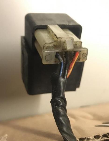
Yep, agree with the Captain. See Attached pic shows it. For Info - Black/Blue = 12v power to Fuel Pump Black = 12v input. Red/Yellow = ICM engine run signal to energise relay. #4 Ignition Coil Ground pulses.

-
Mileage is stored in non volatile memory which is why you can remove the battery and later replace it and Not lose that data. Yes, if you move the LCD to another cluster your odometer reading should be kept. Looking at the bad state of your cluster corrosion wise. A replacement cluster, if you can find one, might be a good option. And its Grum not Chum!
-
Hi Pete. And Merry Christmas to you. Phew...I hope you didn't have to blow all your redundancy payments on that service? Good to hear the bike is running great. Hope your new job goes well, good luck. Cheers.
-
You won't be needing a "shock spanner" 8gen has hand adjustable rear preload. Might be handy for a 6gen owner!
-
The 8gen. has the best and most reliable electrics of any VFR. Numerous previous gen electrical gremlins have been overcome. My voltmeter tells me the charging system produces a rock solid 14.5v at the battery no matter the rpm or selected load eg. hi beam or heated grips etc. Also, if your 8gen VFR, be it hot or cold doesn't start virtually quicker than you can release the Starter Button then something isn't right....they are that good.
-
Hi Billy. Glad you got the all important chain adjusting C spanner. Chain needs replacing! Sounds a little early at 23,000k's but unless the chain was neglected, tension and lubrication wise, then save your money, OEM sprockets should be fine for at least another chain. I've only ever used either RK, EK or D.I.D. high quality Japanese chains and averaged well over 30,000k's per chain, with the four VFR's I've had. My current 8gen has done over 94,000k's, regularly lube, clean and check the chain tension, I'm still running the OEM rear sprocket and has no visible sign of wear, however, I do have a new rear one to fit come the next chain replacement. (somewhere around 110,000k's !) Throwing away sprockets with every chain replacement is not always necessary and will depend on a number of factors! Inspect them before binning them. Where I live we don't add salt to the roads in winter, that probably also helps. And yes with chains and sprockets YMMV. Oh Yes - The chain size you need for an 8gen is a 525 with 110 links. My previous two chains were 124 links that I cut back to 110 (Inclusive of the Master Link). Standard steel sprockets are 16 and 43 tooth.
-
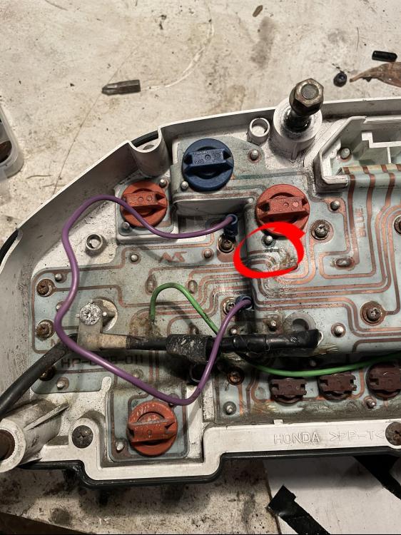
Have you checked sub Fuse A 10amp Clock fuse? Clean up and make sure the 6 LCD mounting screws are making good contact to the copper track. Make sure the electrical plugs are clean and making good contact, a smear of Ox-Gard on connector contacts will help. Follow the Red/Green wire 12v clock power with a meter making sure you measure the 12v at the Blue Connector then follow the track to the top right screw of the LCD, check for 12v at this point, check all the six copper tracks for the LCD. After having a good look at a clean instrument panel picture I have, that Purple Wire link is NOT correct. Its jumpering 12v power of the Brown/Blue wire 12v from fuse G, to the 12v Battery Clock Power of the LCD Red/Green wire from fuse A. Have a close look in the area circled in red, its very suspect as being open circuit, thus the reason possibly for wrongly linking another power source using the Purple Wire link! Download this excellent colour wiring diagram of your bike it will help you with wire colour codes mentioned and the Instrument Panel wiring etc. Bottom line is to Firstly - Remove the Purple Wire link. Secondly - Repair the suspected open circuit track highlighted and, confirm with a voltmeter that you now have 12v via the Red/Green wire with Ignition Off at the top right LCD mounting screw which is where the clock 12v battery power goes to. See the second picture for what your repair might need to look like, the small red circles show open circuit corroded copper tracks that the Red wire bypasses.
-
WARNING - Be very careful when cleaning the Throttle Body not to damage the Molybdenum seal coating for the butterflies do that and you'll end up high rough idle, you could end up needing a replacement throttle body assembly!.
-
Another thing, If your valves were so badly out of adjustment to be making that amount of noise I'm guessing your bike would run like a chaff cutter and possibly difficult to start!! However a CCT issue has no effect on performance appart from the noise, generally speaking.
-
No worries RC79. Good luck and see how you get on with the CCT replacement. I'm sure she'll be good for another 200,000miles!! P.s Nice clean looking 8gen considering its mileage, well cared for, I like that.
-
I'll still put my money on a dud CCT. And surely worth eliminating first. Just establish whether it's the front or rear causing the issue, hopefully it's the rear, an easy one to replace. I'm surprised they decided to simply replace both at the 60k Service! CCT's are generally replaced when noisey Not on a distance spec or service interval..
-
Great effort achieving 117,000 mile! Video 2 definetly sounds like a CCT issue, not valves, also the fact that its More noticeable on the Right side of the bike where the timing chains travel. Listen closely to determine if it's the front or rear cylinder pair that's chattering then replace the appropriate CCT. Wouldn't be surprised given your mileage for a CCT to be the problem. Hopefully an easy and not too expensive fix. Good luck, let's know how you get on. Cheers.
-
Hi Mike. Sorry, but the manual is very clear for what cylinder 2 should be adjusted to! It firstly states to "Adjust each intake vaccumm pressure with number 1", that implies cylinder 2 is matched to 1. Then there are the specific adjustments for 3 and 4. Here's "the real deal" correct adjustment for a 5th gen. Service Manual is confusing for cylinders 3 and 4. See the link below for further info. Cylinder 1 = Master, reference. Cylinder 2 = Match to 1. Cylinder 3 = 20mmHg MORE than 1. (NOT "dropped"). Cylinder 4 = 10mmHg MORE than 1. https://www.vfrdiscussion.com/index.php?/forums/topic/94504-5th-gen-starter-valves-sync-incorrect-for-last-22-years/ Here's some interesting Honda info I found specific to the 5th gen......... "VFR800FI Idle Air Control - A starter enrichment valve controls airflow to each cylinder at idle speeds. The starter enrichment valves allow air to bypass the throttle valves at idle to keep the engine running and provide a fast idle for engine warm up. The VFR800FI is unique because the starter enrichment valves are adjusted to different vacuum readings to compensate for differences in exhaust length between cylinders."
-
5th Gen - fuel pump runs continuously and engine not starting
Grum replied to TDChip's topic in Electrical
You didn't mention this, how are we supposed to know? I won't ask why you removed the whole Ignition System. In order to help you with your situation proper details of what you've done to save us guessing will help a lot. A classic example of poor electrical fault finding are statements like, Fuses look good, I''m guessing its this or that, Grounds look good, etc. Measure voltages or continuity to confirm statements like this. Getting back to your FCR bypassing - If you'd only taken a short time to understand how a simple relay works and a quick look at the wiring diagram you would have realised ONLY the relay main contacts of the Relay connector (Black/White wire to the Brown Fuel Pump wire) needed to be shorted to continuously run the Fuel Pump. Then if you looked at how the relay coil is controlled you would have noticed the constant 12v from the ESR and another wire going to the ECM which has to be a Ground. A word of advice regarding Honda's wiring - A Black wire does NOT always mean its a Negative, nor does a Red mean it's always Positive. Examples...... - The all important Black/White wire on the ESR, FCR, ECM etc is the main +12v for ALL your EFI stuff. - The Black wire from your Kill Switch to the ESR coil is +12v - The other side of the ESR coil is Red/Orange wire, this is Negative/Ground, controlled by the BAS (Bank Angle Sensor). Seriously......Be very careful with whatever you do regarding your bikes electrical system, assuming and guessing is not an option as you've just discovered. Costly, time wasting, and further complications can easily be introduced. If you are not competent with the electrics, you really need to find someone who is. The 5th gen can have some tricky Ground issues, and once your engine is running, a thorough check of the charging system should be done. Once these issue are checked and sorted the 5th gen is a fantastc bike, especially the Yellow ones!. Oh yes, and don't forget the other maintenance issues, especially flushing the old coolant, brake and clutch fluids, etc. Again, Best of Luck with the bike. -
5th Gen - fuel pump runs continuously and engine not starting
Grum replied to TDChip's topic in Electrical
You assumed you knew how to bypass the FCR, then wonder why the Fuel Pump continues to run! Now you're assuming your code 19 is because you've removed the injectors. Why no Injector codes then? Code 19 is an Ignition Pulse Generator Fault! Not a Fuel Injector Fault or "pulse ignition system fault". - Don't assume or guess things, use the wiring diagram and the Service Manual. A Digital Multi Meter is your best electrical tool, it's knowing how to use it that counts. Best to recheck when you have a replacement ECM fitted. As mentioned, who knows what damage is done to the ECM internals, it could be sending erroneous fault codes for various systems. -
5th Gen - fuel pump runs continuously and engine not starting
Grum replied to TDChip's topic in Electrical
???? Is that how you interpret a code 19? You're "probably" just guessing I guess.!! -
5th Gen - fuel pump runs continuously and engine not starting
Grum replied to TDChip's topic in Electrical
Sadly (damn shame actually), you should have closely looked at the wiring diagram for your bike as well as having a bit of a read of the Service Manual (downloadable from this forum) before doing what you did! Section 5 of the Service Manual, Fuel Flow Test actually shows you how to bypass the FCR. To just simply jumper wires that you had no understanding of is a fatal mistake! By placing +12v on the Ground (Brown/Black wire) from the ECM to control the FCR will have blown the internal switching for Fuel Pump control - rendering your ECM useless. You created a Dead Short +12v to Ground, passing through the ECM, either Sub Fuse B 20amp would have Blown OR the ECM blown open circuit, the ECM is by far the weakest link in this situation! You will have no fuel prime or fuel pump operation controlled from the ECM, who knows what other internal damage may have been done. You might have the Fi Light (MIL) permanetly On meaning serious issues with the ECM. To answer your previous question - The ECM receives no direct feedback from the fuel pressure regulator. At switch On, the ECM provides a Ground for the FCR Coil to energise it and run the Fuel Pump for approx 2 to 3 secs then turns OFF. Once the engine is cranked over for starting and the ECM receives Crank Pulses it will again energise the FCR to run the Fuel Pump. Good luck with the bike and sourcing a replacement ECM! -
5th Gen - fuel pump runs continuously and engine not starting
Grum replied to TDChip's topic in Electrical
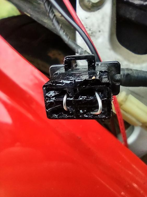
If you've bypassed the Fuel Cut Relay to get your pump running then that is the reason the pump doesn't stop after Ignition Switch On! The ECM controls the Fuel Cut Relay coil Ground side, with it bypassed this cannot happen. BE EXTREMELY CAREFUL IN BYPASSING THE FCR, GET IT WRONG AND YOU'LL DESTROY YOUR ECM! You only need to jumper one of the Black/White wires to the Brown wire NOT the Brown/Black ECM wire. Unfortunately, looking at your photo it appears like you may have done just that, jumpered 12v to the Brown/Black ECM Ground output for the FCR.!!!!! There should ONLY be one jumper wire. See Attached photo - The guy that did this destroyed his ECM, does the jumpering look familiar? No the relay socket hasn't melted, its just drowned in Dielectric Grease! For Info - You can always use say the Hi Beam Relay in the Fuel Cut Relay position as Hi Beam, Lo Beam, Fuel Cut and Engine Stop Relays are the same type.
-
Hey Dutchy redslut must have died when the Sidestand gave way.... nice angle that!!!!
-
Congratulations Kenny and welcome. The 8gen is an incredibly reliable bike. How about some pictures of the new toy? Good luck with the purchase.

.JPG.234e4e6f14bc81a2559f6c1fab355d44.JPG)