DannoXYZ
-
Posts
1,237 -
Joined
-
Last visited
-
Days Won
27
Content Type
Forums
Profiles
Gallery
Blogs
Downloads
Events
Everything posted by DannoXYZ
-
Great, thanks! 🙂
-
Awesome, good job! To verify, can you measure voltage on that pink-wire at blk ECU connector? Just want to check to see what exact voltage is that it's expecting. Thx
-
That fried fuse-holder should never have had 30-amp fuse in it. Should be 20-amp only. Since larger-than-designed fuse was installed, it didn't blow quick enough and too much current surged through circuit. That's why stuff is melted. Possibly blown up and damaged beyond repair. How many times did you replace that blown fuse with another 30-amp one? Need to find that short, cut it out and replace all melted wiring.
-
So did original ignition run bike before keys were lost?
-
When was ignition-switch replaced? With OEM unit from authorised Honda dealer? Post photo of bottom of your original ignition-switch. USA bikes don't have HISS immobiliser, but it does have pink wire from ignition-switch to ECU. Look on your ECU for pink wire at A12 position on blk connector.
-
What's history of this bike? When was last time it worked perfectly? What happened between then and now? Blowing fuses is symptoms or results of actual problem. Fix the problem and fuses won't blow (cause & effect). Why fuse blows is most likely due to short in wiring. Trace fuel-pump circuit starting from battery to fuel-pump end and look for any connections that are not correct. Look for melted-insulation with bare wiring exposed and touching other wires or frame.
-
 Solution may be to get PowerCommander and make adjustments. From gropula's corrections map, it appears factory settings are way, way too rich in low-load cruising zones. Had to remove more than 1/2 of fuel!!! No need for wideband and tuning, he's already done that for you. Just download his map into PC and done! 🙂
 -
ah, sorry, thinking of old coils. Yes, these are the coils we're looking for..

-
Definitely wiring problem. Voltage should be full battery-power or 0v. Something's very, very wrong... We'll see results of Grum's and coils test and go from there.
-
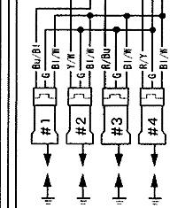
Something got re-connected wrong when you took everything apart, replaced fuel pump and put it back together. For coils, no grounds on coils. Should never ever be connected to ground! If so, something may have blown up 1st time you turned key ON. Do these tests: 1. unplug all coil connectors 2. key ON, start/stop = RUN 3. measure for voltage on both terminals of each harness-side coil-connector. 4. report all 8 measurements here This is related to power for FP as well. So bad connections to coil will definitely affect both engine-stop relay and FCR.
-
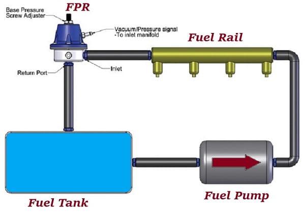
Pressure only exists between pump and FPR. Doesn't matter where you measure it, pressure will be same at any point in between. Pump actually doesn't generate much pressure on its own, just flow volume. It's FPR at other end of rail that creates restriction. It's pump trying to force fuel through this restriction that backs up and creates pressure in rail. More restrictive the FPR's setting, the more pressure is created between pump and FPR (rail). It's like flowing garden hose, very little pressure. Until you stick thumb over end to restrict flow. Then flow is backed-up hose and generates pressure. The tighter you squeeze opening, the higher the pressure.
-
That is just one failure mode of FPR. But it can also fail and not leak. Resulting in too high fuel-pressure. A test of FPR is to take 2-measurements of fuel-pressure in rail. One with vacuum hose disconnected. And one with it connected. Difference should be proportional to vacuum applied. You can get tester with Autozone's free rental programme. Just put down deposit for kit, then get it back when returning kit.
-
Hello! So here is a video of how I tested the map for Volts at 3k rpm. Please advise if correct or if I'm dumb lol video cuts off. But at 3k rpm it went from 2.3 to 2.0 Follow procedure in manual. You want to measure voltage on MAP-sensor output line to ECU. That's how ECU is getting data about environmental conditions. Measure voltage between lt.grn/yel signal wire using grn/org as ground. 1. key-ON, output = 2,7-3,1v 2. engine idling= 2,7v max Do same measurements with BARO sensor, output-voltage on lg.grn/blk, grn/org as ground. Graph output-voltage measurements at various RPMs and it should fall into these ranges (need to translate altitude into absolute-pressure/vacuum). vacuum in intake at idle should be 200-250mmHg. fuel-pressure at idle should be 36psi fuel-pressure at WOT should be 45-50psi.
-
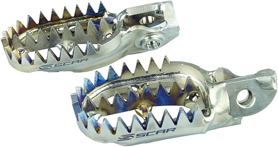
You need some of these footpegs: https://www.scar-racing.com/en/products/456-titanium-footpegs.html
-
Ok, no 5-way joint on your bike. Use this vacuum-gauge to measure vacuum going to MAP sensor. Use T-fitting to tap into hose in-line with MAP sensor. It's primary sensor that ECU uses to calculate air-flow volume to determine how much fuel to inject. https://www.amazon.com/Actron-CP7803-Vacuum-Pressure-Tester/dp/B0006V2BS2 At idle and low-loads, vacuum is high and ECU injects little petrol. At higher-loads and larger throttle-openings, vacuum is low and ECU injects more fuel. What often happens is vacuum hoses develops cracks and leaks, or get disconnected slightly when tank is removed and reinstalled. This vacuum leak lowers vacuum levels going to MAP sensor. It will read lower vacuum than actual and tricks ECU into thinking load is higher than actual. ECU then injects more petrol than required because it thinks load is higher. So you're cruising along with throttle barely open, but ECU thinks you're WOT!! Easier to just measure output voltage of sensor. Don't even have to take tank off. Then if numbers don't line up, you can crawl in there to measure vacuum and inspect for leaks There's possibility that FPR has malfunctioned. Its job is to vary fuel-pressure according to load based on... intake vacuum! At low-loads and low fuel-demands, it lowers fuel-pressure. At high-loads it raises fuel-pressure. Leaks in vacuum hoses would cause it to send too-high pressure to fuel-rail. Only way to know for sure is to measure fuel-pressure in fuel-rail.
-
Measure vacuum in 5-way T that goes to MAP-sensor at idle and 3000rpms. Measure MAP-sensor voltage output at idle and 3000rpms. 4 numbers total.
-
We had huge thread just little while ago about how tightening axle out-of-sequence caused issues. Someone was confused about uneven gap between sides? Optical illusion? Apparently there's enough play between each of those parts that accumulated tolerances from beginning to end can thrown system out of whack. Each part's +/- variations can add up in wrong direction with final part being out. I heard one guy finally solving his issue, which was glob of paint under fork-tip axle-clamp that caused enough mis-alignment to result in shaking while braking. In my case, I still have no idea what it was. I just followed Dave's video step-by-step and it worked!! 🙂
-
These videos really helped me solve front-end shake issue that was bugging me for months! I had already replaced every single part in front-end except for forks & wheel. Every single wear item. Was getting ready to park track-bike in storage and find another bike.
-
I think he means for which model & year. Banjo bolt washers are most likely 10mm. Copper ones can be annealed and re-used.
-
New 5th/6th/8th gen performance header now in production in USA
DannoXYZ replied to sfdownhill's topic in Exhaust Systems
Ah yes, need to keep ID clear. -
New 5th/6th/8th gen performance header now in production in USA
DannoXYZ replied to sfdownhill's topic in Exhaust Systems
What OD did you trim them down to in order to fit? I've used these on my RC24 & RC26 and they fit perfectly. Expands to about 41mm when crushed. https://www.aliexpress.com/item/3256805023890622.html Looks like 800 also uses 40mm gasket https://www.ebay.com/itm/195539730170 -
95 vfr 750 engine stalls after shifting in to gear
DannoXYZ replied to Bryanzx6r's topic in Third and Fourth Generation VFR's
Important safety-feature as well as for operations. https://www.ebay.com/itm/204155108287
-
How to remove power limitations 1st and 2nd gear
DannoXYZ replied to Dutchgixxer's topic in Seventh Generation VFR's
Ok, you can get generic conveter cable and attach proper Honda DLC connector: https://www.amazon.com/Serial-Adapter-Signal-Prolific-Windows/dp/B07R8BQYW1/ https://www.corsa-technic.com/item.php?item_id=341&category_id=54 Pin-outs -Black/white > +12V -Orange/White > K-line -Brown > SCS can jumper to flash error codes -Green > ground The ECU does not speak OBD2 language, but much, much older analogue serial K-line protocol. Similar to modem AT commands for those familiar with dial-up modems. Downloading flash image .BIN file takes 15-minutes @110 baud !!! 😛
-
95 vfr 750 engine stalls after shifting in to gear
DannoXYZ replied to Bryanzx6r's topic in Third and Fourth Generation VFR's
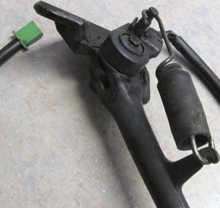
One or more safety-interloc switches are broken or wiring in between is broken. Measure clutch, sidestand and neutral switches and verify they work properly. Then measure line to ECU and verify signal actually nakes it there. Could be corroded terminals in connectors or broken wire along way. -
How to remove power limitations 1st and 2nd gear
DannoXYZ replied to Dutchgixxer's topic in Seventh Generation VFR's
It's a basic USB/serial to TTL converter cable. Can build your own with instructions here: https://github.com/AlexKovalevich/HondaECU Heck once you've reached that site, you might as well download all the software to edit maps and flash them to ECU yourself. He's got stock and modified .BIN files for download with 1st/2nd gear restrictions removed.