Grum
-
Posts
3,827 -
Joined
-
Last visited
-
Days Won
119
Content Type
Forums
Profiles
Gallery
Blogs
Downloads
Events
Everything posted by Grum
-
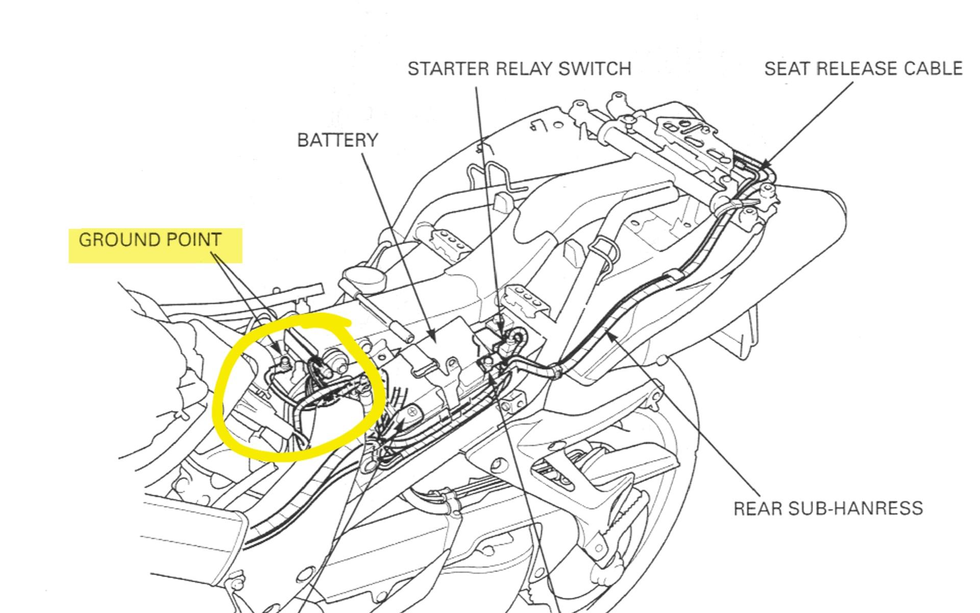
If the Ground path control for the FCR within the ECM is blown there may be other consequences within the ECM. Having the Fuel Pump running constantly without ECM control removes a certain amount of safety protection, and anytime you have the Ignition on the Fuel Pump will be running constantly, not a really good scenario. But, its your bike and possibly doable provided there's no other damage to the ECM. But before going down that road, suggest the ECM Grounds and Orange Ground block need Very Good checking. Also check the Frame Grounds are clean and tight and have zero ohms continuity to the battery Negative terminal. Refer Section 1 of the Service Manual for Ground locations.
-
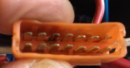
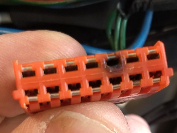
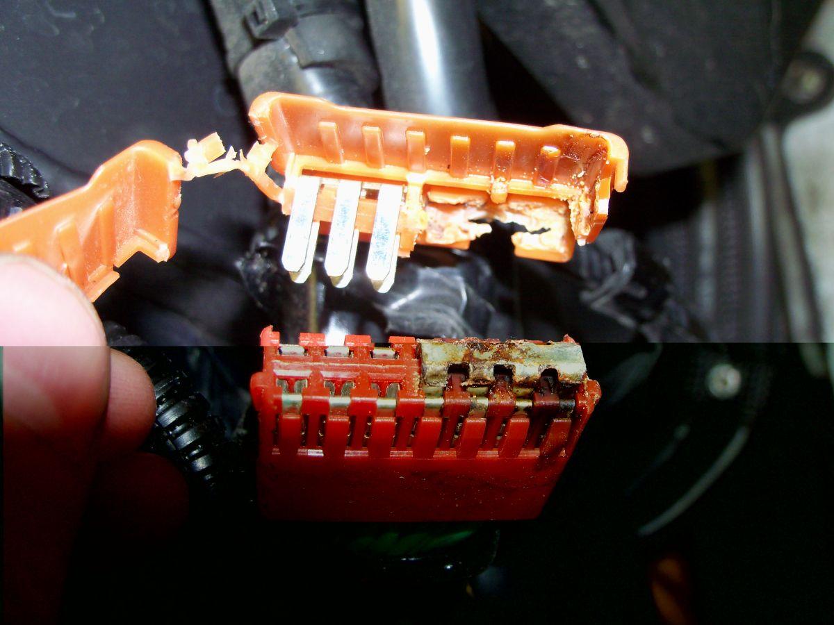
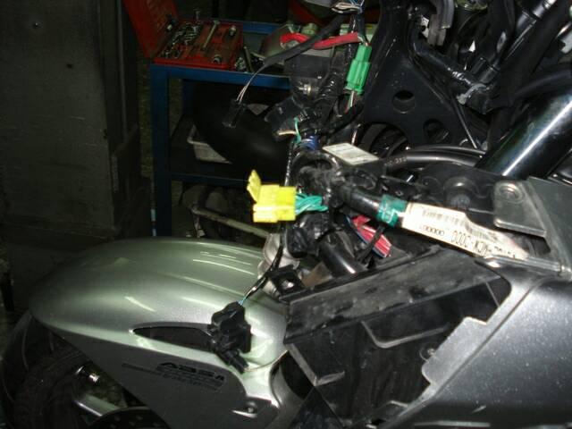
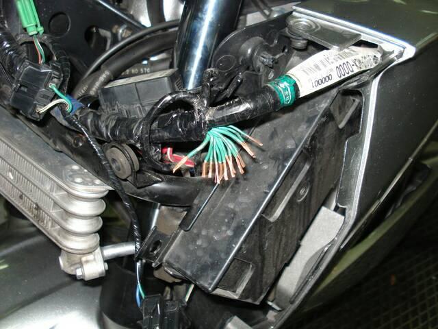
Your ECM is not providing the required Ground on the Brown/Black wire to energise the FCR. 1. You haven't made it clear if you unknowingly or accidentally applied the Black/White wire power to the Brown/Black wire when jumpering? If you did then you've blown the internals of the ECM. If you saw zero volts with that test, then I'm thinking you have zapped your ECM! Even with a bad ground (unless its open circuit) you possibly should have seen some form of low voltage during the 3sec switch On prime. 2. If the above doesn't appply, then you need to check the ECM Grounds. According to my drawing the ECM Grounds are at A9 and A20 both Green/Pink wires and B1 a Green wire. These should measure near Zero ohms continuity back the the battery Negative terminal. This will most likley lead you to the dreaded Orange Ground junction Block located in the wire harness just above your Chain Guard. See pictures. Do a very close inspection of this. Bad Grounding within this block causes a multitude issues with sensors and the Fuel Pump FCR operation. Within the block there are Two Genuine Ground wires, all the other wires are joined up via a buss bar and connectors to the Genuine Ground wires. The repair is to cut the block out and neatly solder ALL wires together and heat shrink sleeve the bundle, then tape it back onto the wire harness.

-
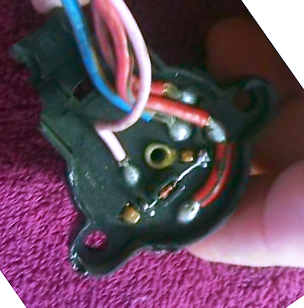
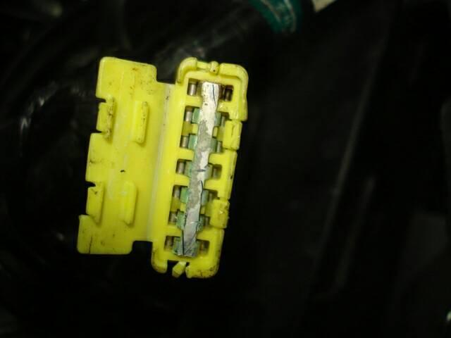
You didn't answer if you hear the relay click/energizing at switch On? From your description it appears the Relay is Not being energized from the ECM. Another Important Question - When turning Ignition to ON, does your Fi Light come On then switches OFF after the 3secs fuel prime time, OR does it remain ON? If it remains ON Check your Ignition Switch wiring, does it have 4 wires and is one of them Pink? This Pink wire is a hot wiring security feature and if the correct voltage (set by a Zener Diode on the bottom of the Ignition Switch) of 9volts is Not sent to the ECM it will not enable the Fuel Pump. See attached picture of the Ignition Switch base. Don't forget, at switch On the Fuel Pump should only run for about 3secs. The Relay will only energize for that time. Once cranking and running is detected by the ECM the FCR is again energized running the Pump continuously. With your meter set to voltage and Red lead on the battery positive. Probe the Brown/Black FCR wire with your Black meter lead. At switch On are you measuring 12v for about three seconds then the voltage should disappear?
-
I sure hope when you did the Jumping that you Never accidentally applied the 12v Black/White wire power to the Brown/Black wire as this Will destroy your ECM? The ECM supplies the Ground side for the FCR coil on the Brown/Black wire to energize it and run the fuel pump. - Do you hear the FCR click at Switch On for a few seconds? - If you are only seeing 4v on the Brown wire for the Fuel Prime duration, you may have high resistance contacts within the Relay itself, a faulty relay or poor contact connections within the relay socket. Are there any visible signs of corrosion in the socket? - Try swapping the FCR with your Hi Beam Relay. The four relays being Hi Beam, Lo Beam, ESR and FCR are all the same type. Good Luck. Let's know how you get on.
-
So have you got the bike going after all your Ground and electrical problems? Considering all the input that went into that issue, it would be kind of you to at leat post What the fix was?? So we can ALL learn.
-
Hi Grum, Thank you for your donation of 50.00 USD. We look forward to improving the forums with your donation. Thanks VFRDiscussion
-

Bike used to shut off randomly, now has MAJOR grounding problems
Grum replied to styran's topic in Sixth Generation VFR's
Wonder if your version VFR has this front harness Ground Block, needs a good inspection if you have.
-
Bike used to shut off randomly, now has MAJOR grounding problems
Grum replied to styran's topic in Sixth Generation VFR's
- Check the BAS Ground wire for continuity back to Battery Negative. What do you measure? - Have a close look at where this wire goes through the 18P Blue connector, bad joints and problems have occurred here. For fault finding at this stage keep the BAS bypassed, it stays out of the equation that way. Get the wiring and bike running first Then go back to reconnecting the BAS back to normal. - If there is any suspicion of an issue with the ESR, replace it with the Hi Beam Relay. You can only have a partial short or bad Ground, otherwise you'd be blowing a fuse. So you've confirmed all major grounds including engine ground are clean and good (not just tight) and measure zero ohms back the battery Negative? See attached picture.
-
Bike used to shut off randomly, now has MAJOR grounding problems
Grum replied to styran's topic in Sixth Generation VFR's
Well, as mentioned above for Ground checking, you Must establish why you have a Ground integrity issue First..... All grounds must have zero ohms/continuity back to the Battery Negative, and no ground should measure a voltage with respect to Battery Negative, ignition to On and Off. Check ground bonding starting with the Engine and Main frame Ground. I'm assuming battery terminals are clean and tight and you have a charged healthy Battery? -
Bike used to shut off randomly, now has MAJOR grounding problems
Grum replied to styran's topic in Sixth Generation VFR's
Holy Cow!! You seem to have gone badly backwards from just replacing the Starter Relay plug! Are you confident the wires in the plug ARE going to the correct connections at the Starter Relay? Assume you're saying it cranks over but doesn't start? Is that correct. Cranking excessively trying to start it has probably caused flooding. Might require you to go through the purge process of throttle Fully open while cranking, shuts off injectors purging cylinders. So if your battery voltage is say 12.5v and you leave your positive meter lead at the battery and you probe any ground point or wire and you're seeing noticeably lower than the 12.5v. This would point to either a bad Negative connection at the Battery or poor main Ground to frame or engine. Your messing with my head referring to frame ground power! If you have a meter lead on the Battery Neg terminal And you probe any Ground with the other lead AND you measure a voltage, then the Ground is Not properly Grounded. Any suspicion of the BAS. For test purposes you can easily unplug it and bypass it to enable the ESR at switch On. You just need to link the Red/Yellow wire to the Green of the BAS. So the Starter, BAS fuse is Not blowing, but somehow upsets power or ground?? Suggest taking good Voltage measurements with the Negative meter clipped onto Battery Negative Probe..... -12v on Black wire of the ESR Ignition to On. Voltage should come and Go as you operate the Kill Switch. - 12v Solid on the Red/White wire of the ESR. This should be there All times Ignition On or Off, source is Main Fuse B 30amp. - 12v On the Black/White wire of ESR Ignition to On. Another weak link with the above voltages is the Blue 18P connector, refer your drawing, common problems of high resistance and poor connections can appear at this connector. Monitor the voltage at the Clock Fuse probing the tiny fuse test point on top of the fuse. You must see battery voltage here Ignition On and Off. This will confirm Main Fuse A 30amp power is good or bad! Do the same for the Headlight Fuse F. This will confirm Ignition Switched power is OK or faulty, again you should be measuring battery voltage. -
Not having a 1200, but can assure you the 800 in slow moving stop start traffic can bring on the cooling fan fairly quickly even in cold weather. However 15-20sec in 10degC sounds a bit suspicious. I take it you have confirmed good coolant levels in the reserve tank? No obvious coolant leaks? Radiator cores not obstructed with leaves, insects etc? Possible thermostat issue!
-
?? Did you see his video of the fault code? Sure looks like a 23 to me.
-
Well if it stinks of fuel plus your running symptoms, then the first and easy thing to check is the FPR for a ruptured diaphragm. Dumps excessive raw fuel into 3 and 4 via vacuum hoses. Remove the FPR vac hose, see if fuel is dripping from the FPR or the vac hose wet with fuel = ruptured diaphragm.
-
Wonder if you have a leaky/ruptured Fuel Pressure Regulator diaphragm? This will dump excess fuel into cylinders 3 and 4 via the vacuum hoses. Might also relate to your bad O2 sensor reading especially if its the 3 - 4 one playing up!
-
Again, No Sir........ The schematic doesn't mislead! The R/R output definetly ends up with ONE 12v line and ONE Ground line. The two R/R outputs are not set up as one to feed the battery and another to feed electrical services! Power distribution all begins with Main Fuse A 30amp and Main Fuse B 30amp, both effectively supplied by battery and the single R/R output. Perhaps in other bikes the dual output wires Might be configured as you say, I'm only familiar with the VFR. The 4P plug arrangement is basically the same for both 5th and 6gen ( appart from the additional voltage sense wire for the 6gen using a 6P plug). The 4P plug is the easy point of disconnecting the R/R from the main wire harness. Having the two grounds and two power wires makes for a better load share throught the spade connectors and makes use of a standard plug with same size spade connections. The main problem with the 4P connector (and the 3phase AC input connector) over time is due to moisture ingress, corrosion and ulitmately high resistance joints, hard wiring can be the best alternative once a good non oem R/R is fitted.
-
Assuming you had No fast idle issue Prior to your coolant flush, then it sounds to me like an air lock situation, adding to poor coolant circulation to the wax unit. Running the bike to high temps without the radiatior cap on will cause the volcanic eruption you had and especially if there is air trapped. Did you follow the fill and burping process in the Service Manual?
-
No Sir! Not when you look at the wiring diagram. The four wires become a normal two wire configuration beyond the 4P connector. The single 12v wire then goes to the battery, protected by the one fuse, Main Fuse B 30amp.
-
Nothing more complex than just being able to supply minimal voltage drop Power output by using two smaller, more flexible cables each for both 12v and Ground, rather than a singular heavy gauge cable for each, makes for easier smaller standard sized interconecting spade connections within the plugs/sockets I guess. The 5th Black wire you mentioned (which I think is from an R/R for 6gens). Is a Voltage Sense feedback wire.
-
2001 VFR800 FI Speedometer and Rev Counter not working
Grum replied to CalvinVFR800FI's topic in Electrical
Tacho and Speedometer are mounted and electrically connected to the pcb by three Phillips screws. Both instruments share the same Power and Ground source. Suggest using the wiring diagram and take some simple Voltage and Ground measurements at the Instrument mounting screws to discover what's missing. 12v power is the Brown/Blue wire, Ground is the Green/Black. See partial drawing attached. A good clean of the connections of the two main Instrument Panel connectors and a smear of OxGard on the contacts is a good thing to do. Have a close inspection of ALL the pcb copper tracks for corrosion and open tracks, these can be easily repaired via a solder bridge wire. Good luck, hopefully your fault won't be too hard to find.
-
You swapped a 1998 5gen ECU with a 2003 6gen ECU!!!! NOT possible! Different connectors, different wiring, different sensors etc !!!! What checks did you do to "realize a problem with the ECU Unit"??? OR.... Are you saying you swapped the FCR (fuel cut relay) with the one from your 2003? Do you have the Service Manual or a wiring diagram to work with? With the Sidestand down, Ignition to On, what is the Fi code being flashed by the Fi light??
-
Bike used to shut off randomly, now has MAJOR grounding problems
Grum replied to styran's topic in Sixth Generation VFR's
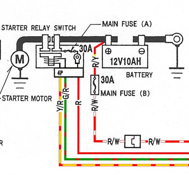
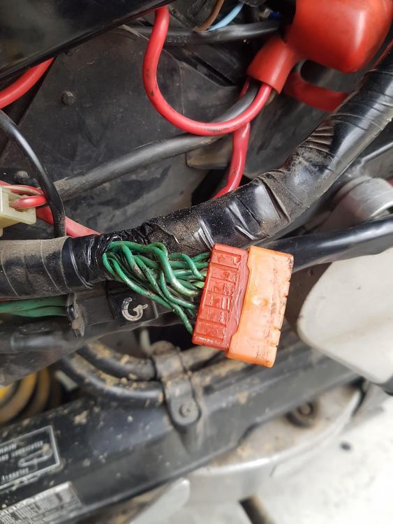
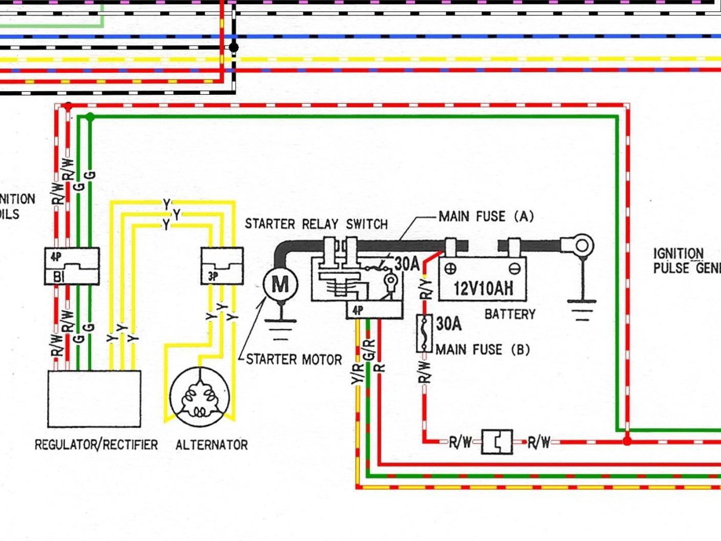
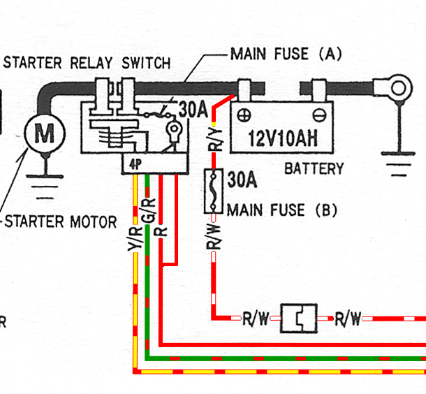
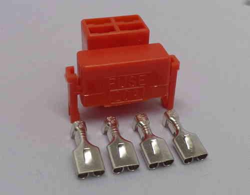
That is definitely heat stressed, the Red wire has turned brown and the red plug has melted, a hot and high resistance joint. Think you've found the fault! The Red wire will need cutting back to good unheated copper and new spade connector fitted. Its not essential to replace the relay coil spade connectors but if you can, then just do it. Replace the red plug with these high quality tin spade connectors, sorry can't remember the web site, just do a Google on Starter Relay Plug replacements should find them. Make sure the Red Wire male spade in the Relay isn't burnt or corroded. You could also try the wiring mod shown using the additional spare spade connector to the Main Fuse to share the electrical load, splicing an additional wire into the main Red wire. Some OxGard on these conections will also help. The coloured drawing is just a section from the 5gen Hi Res downloadable drawing from the forum. Starting circuit and wiring is the same as 6gen.
- 14 replies
-
- 1
-

-
- electrical
- charging
- (and 1 more)
-
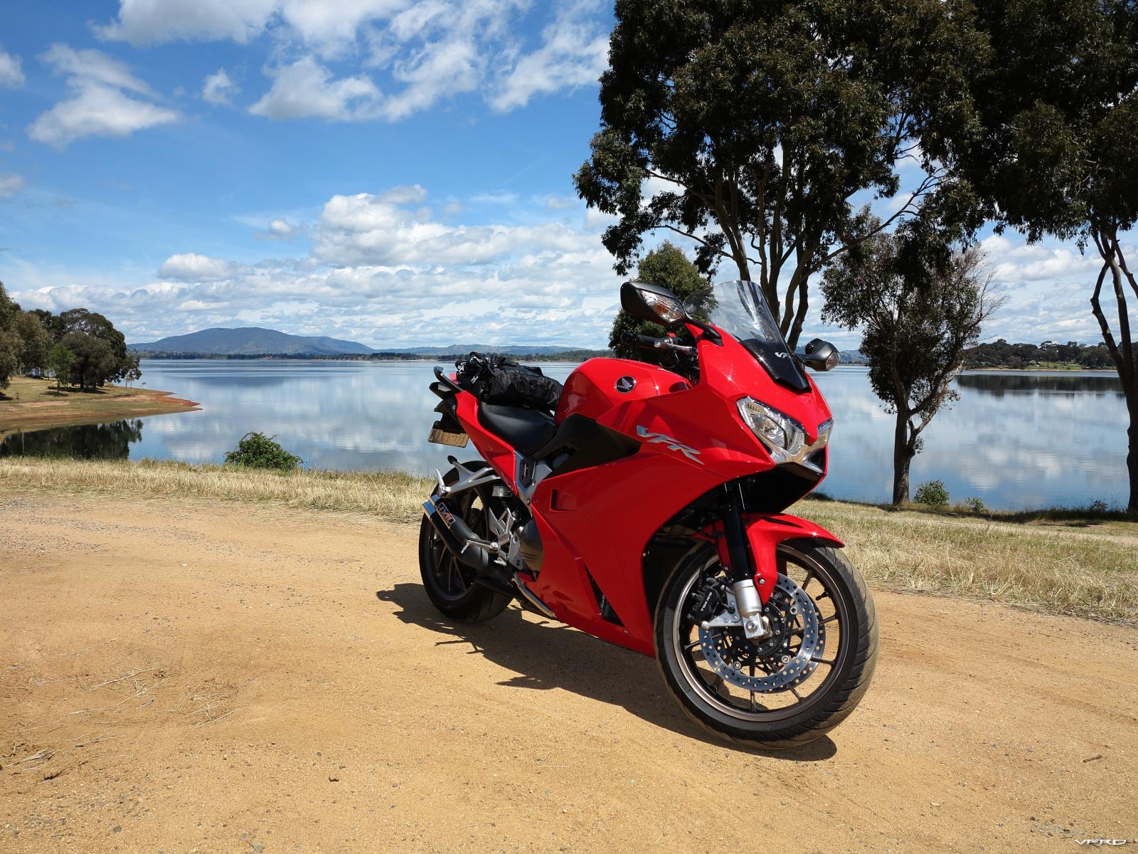
Congratulations Hammy, your dream has come true at last. A very nice looking 6gen. If it's been well cared for it should serve you very well. You can download the Service Manual from this site so you can get to know your bike more intimately. Hope it brings you many miles of riding joy. Find out what servicing has been done, to assess what might need doing in the short term. Regular brake/clutch fluid flush every year or two is very important and so often neglected. Just wondering - Does the Canadian version have H.I.S.S.(Honda Ignition Security System)? If it does hopefully you'll get the two original transponder Ignition keys, if it does and you only get one key, then get a second cut and programmed ASAP. Cheers
-
Bike used to shut off randomly, now has MAJOR grounding problems
Grum replied to styran's topic in Sixth Generation VFR's
No Clock power and resetting is a definite sign of Main Fuse A 30amp power loss, located in the Starter Relay, it will also kill power to the Engine Stop Relay coil = Dead Engine, and power for the Starter Relay coil = No Starter Cranking. Further info - Loss of Clock backup power and it resetting also confirms that the fault can't be an Ignition Switch problem, as backup power is Not switched through the Ignition Switch. Check the Red plug at the Starter Relay. Check for any sign of heat stressed wires and burnt spade connections for the Red wire. Check the fuse and its legs for any signs of heat stress or poor/loose connections. Even though you have replaced the battery it still could be an issue. What does the battery voltage drop to as you attempt to start the engine? Is your replacement battery a good quality item or Chinese cheapy? I've heard of a couple of new battery scenarios that were down on capacity straight out of the box, and not able to hold a charge, it may have been sitting on the store shelf for too long! Let's know how you get on, good luck.
- 14 replies
-
- 1
-
-
- electrical
- charging
- (and 1 more)
-
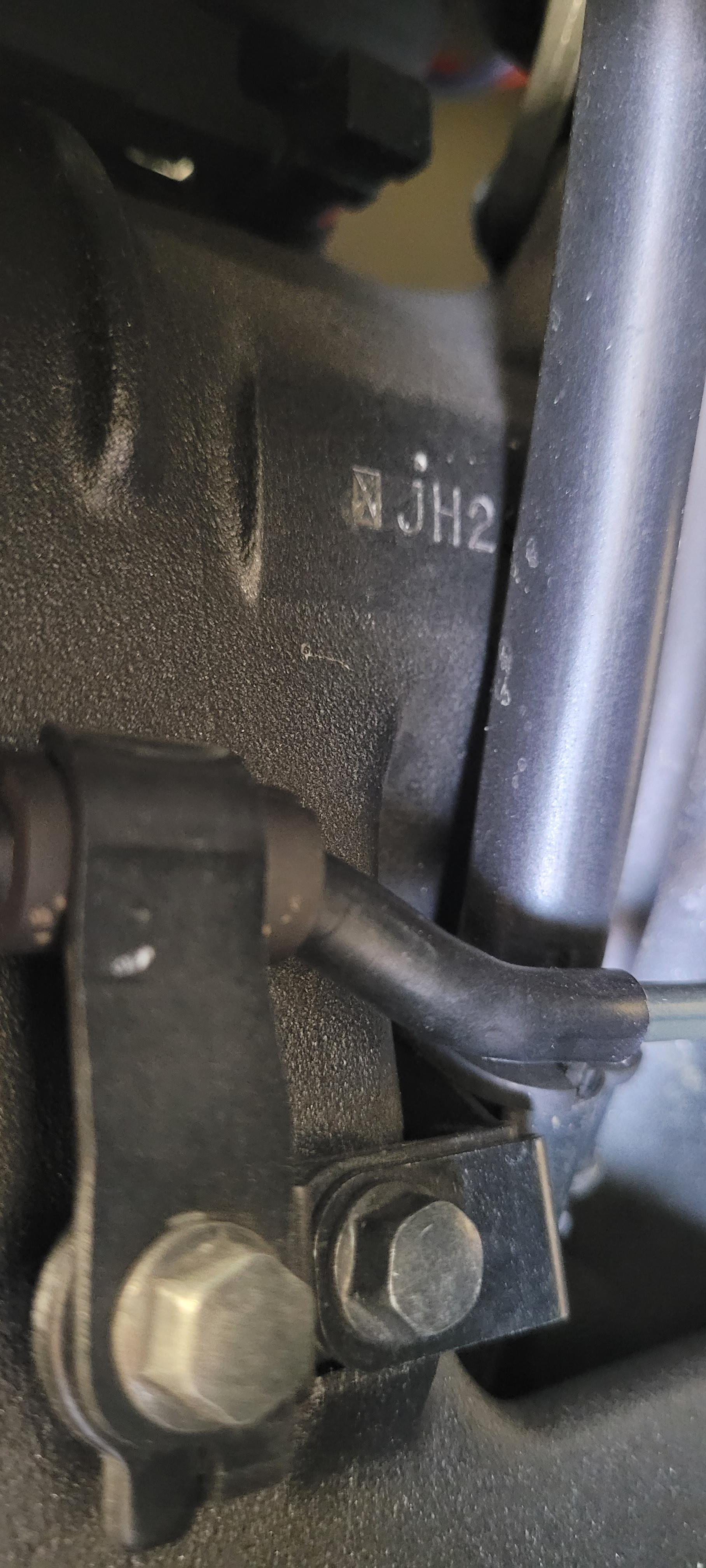
VIN Number is stamped on the R/H side of the steering head. Here's what you should be looking for - a dot stamped just above the J. (Thanks for the pic Skids!)
-
Looking good Lorne. The experience I've had with CCT's is that the clatter noise has always been evident high up at the cam covers on the R/H side, and its not difficult to identify if its the front or rear playing up by the noise location. Clutch basket noise obviously should come from down low around the clutch cover region. So it should be easy to determine whether its clutch or cct noise. Clutch noise might also change (unlike cct noise) if you pull the clutch in. Cheers


.JPG.c7fc62745d583ef2c34a15d3784b0da3.JPG)