n3n3
-
Posts
34 -
Joined
-
Last visited
About n3n3

n3n3's Achievements
")


-
Water Temp flashes 270 all the time with no codes
n3n3 replied to n3n3's topic in Fifth Generation VFR's
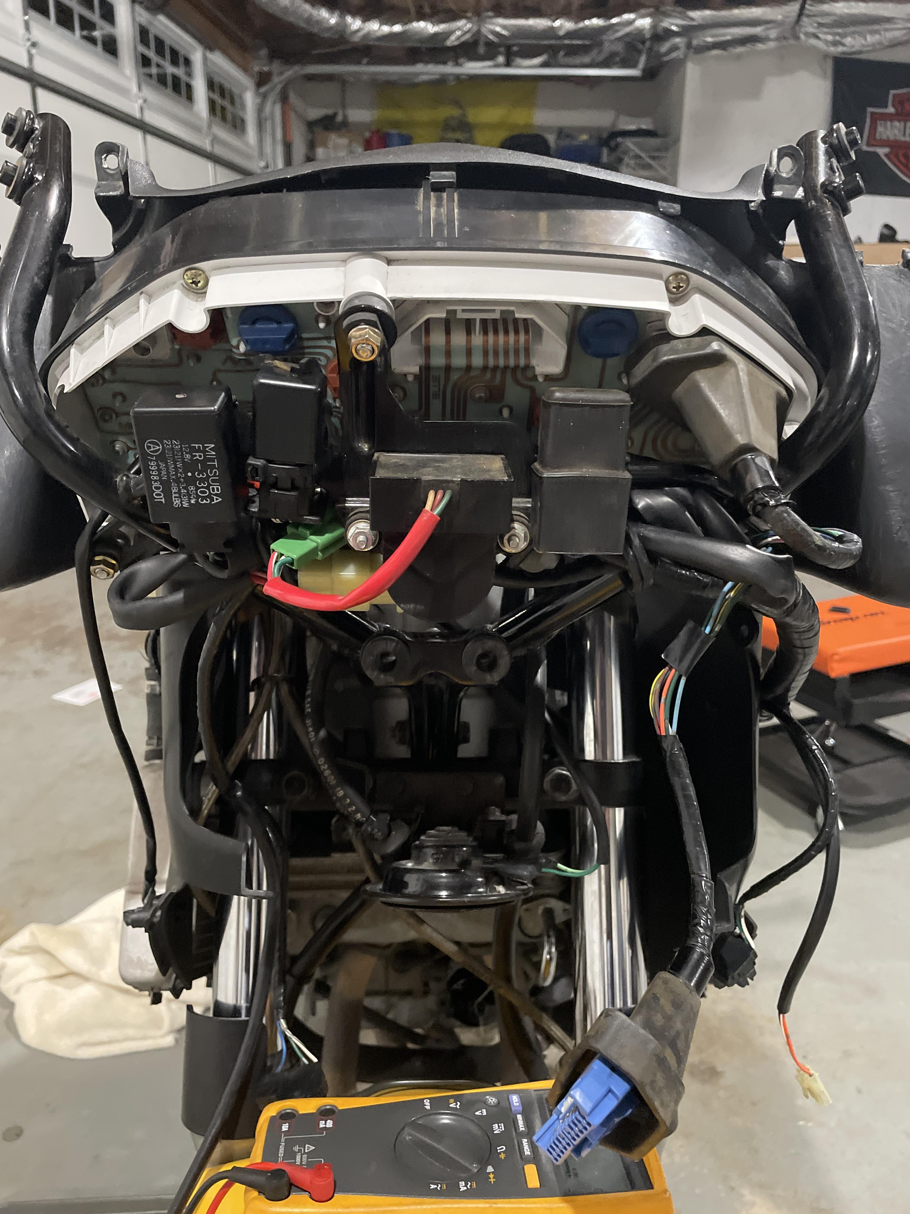
How I used to test a 9 volt battery
-
Water Temp flashes 270 all the time with no codes
n3n3 replied to n3n3's topic in Fifth Generation VFR's
I never new the ECU was bad from the beginning I’m trying to trouble shoot and no just be a parts changer. Grumpy Grum is a joke had to tell but if we were face to face you would know because I would be smiling. I think I might be a little color blind to be honest that’s why I posted pictures. Thanks for your help now get some sleep. Thanks again -
Hi n3n3, Thank you for your donation of --. We look forward to improving the forums with your donation. Thanks VFRDiscussion
-
Water Temp flashes 270 all the time with no codes
n3n3 replied to n3n3's topic in Fifth Generation VFR's
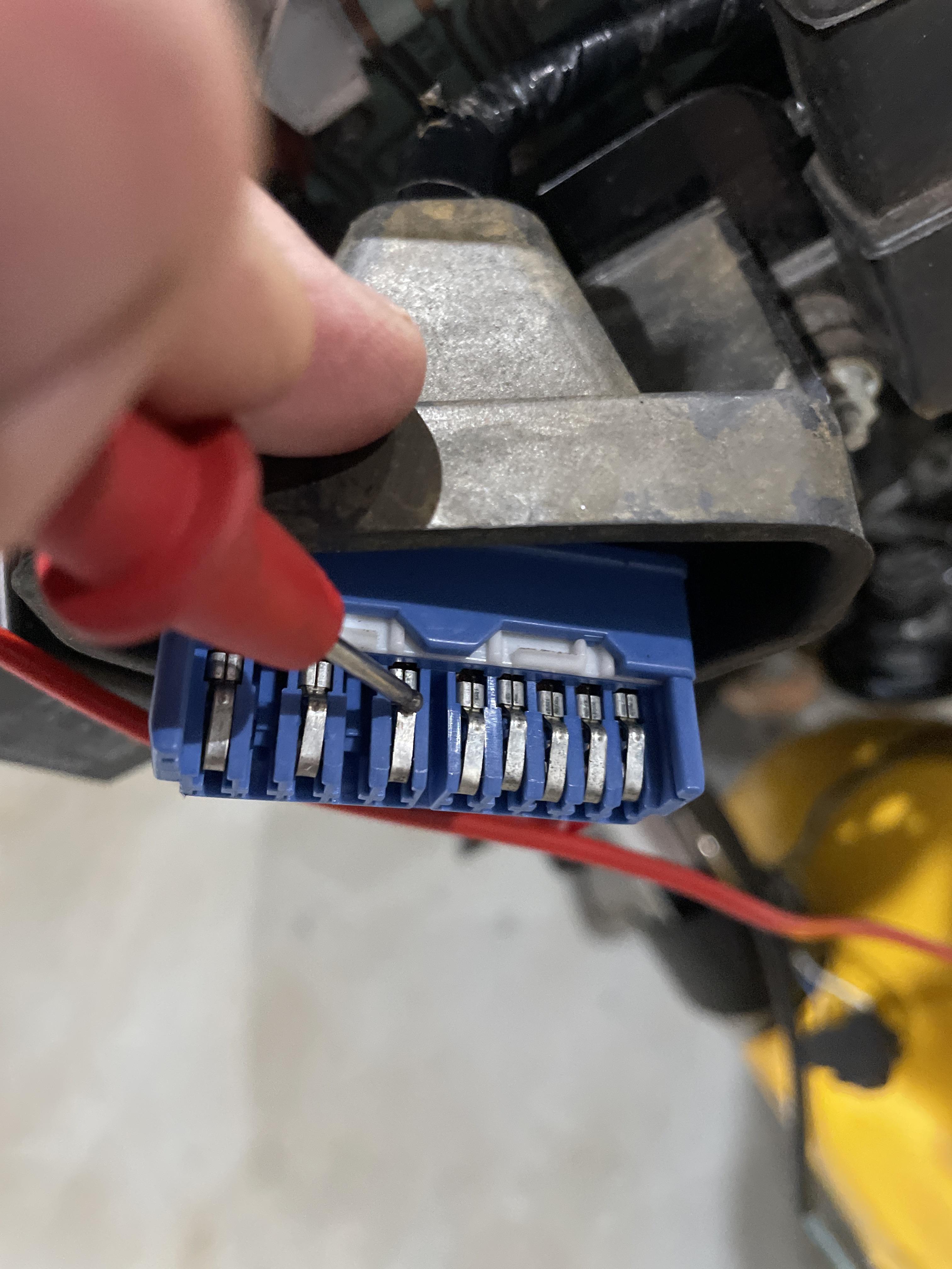
Whatever you want to call this color. I will go with Grumpy Grum says he truly is the expert along with Preston. I have a ECT on order. Thank guys will keep everyone updated hopefully this fixes my issue. With the sensor plugged in I get 30.1 ohms key on or off doesn’t change. To be clear that just the sensor plugged in and continuity to the pin before it goes into the instrument panel
-
Water Temp flashes 270 all the time with no codes
n3n3 replied to n3n3's topic in Fifth Generation VFR's
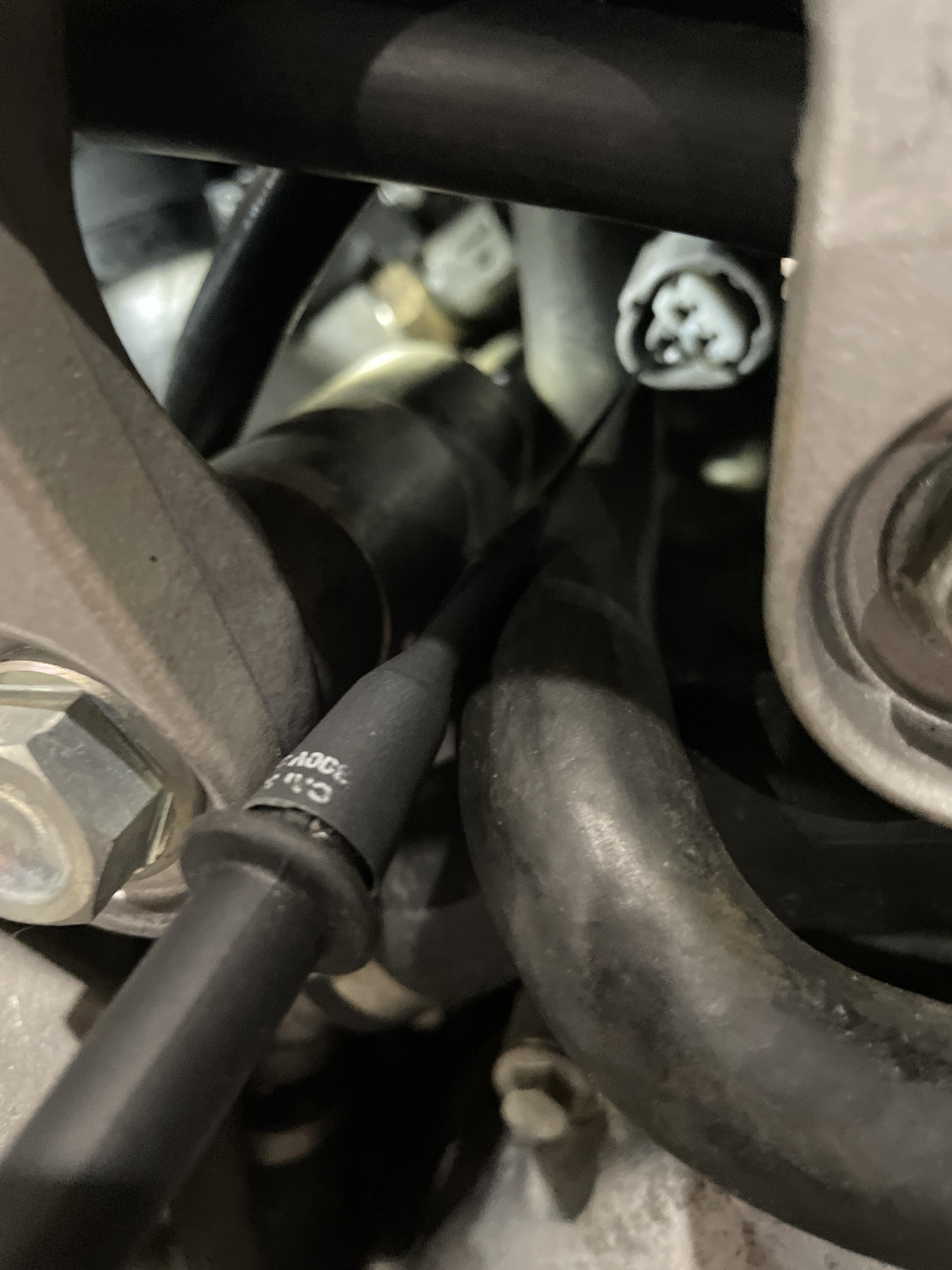
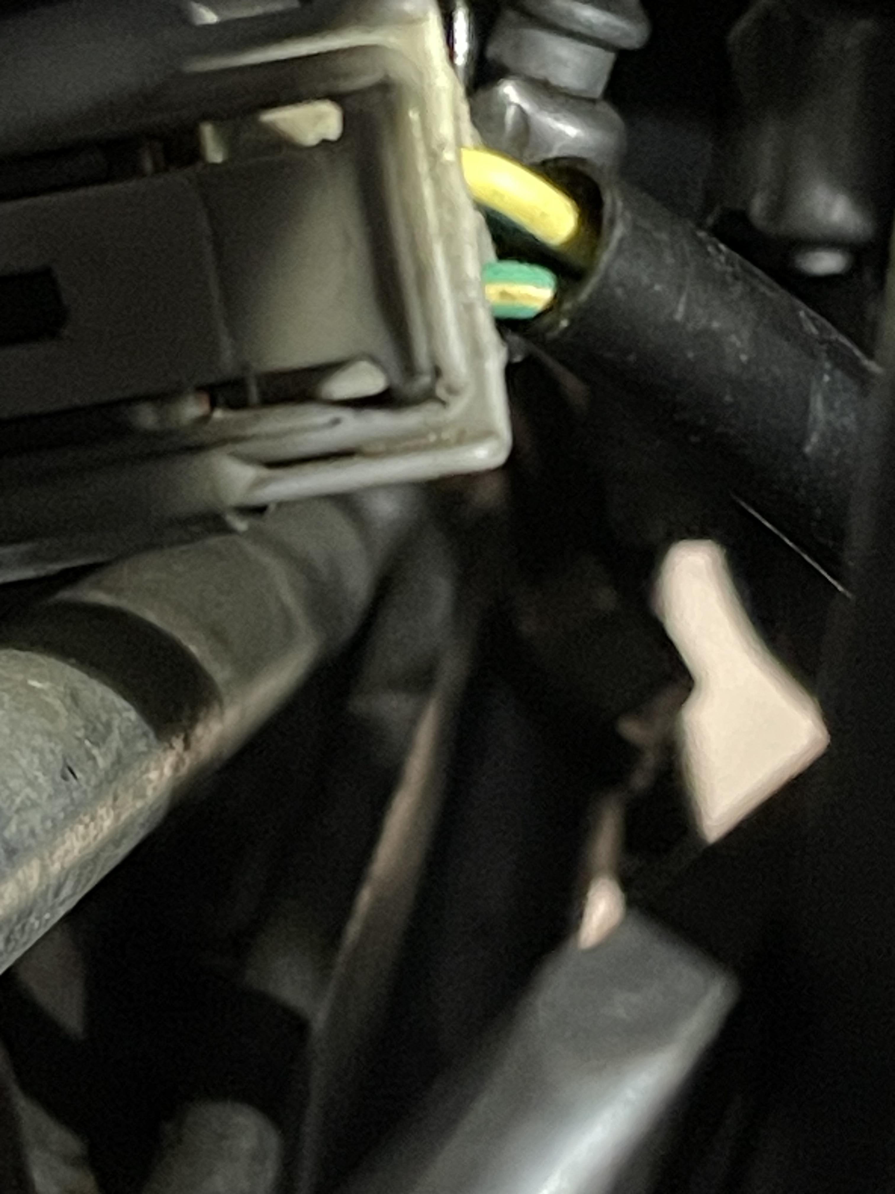
Canon plug to the ECT
-
Water Temp flashes 270 all the time with no codes
n3n3 replied to n3n3's topic in Fifth Generation VFR's
I have continuity from the ECT wire
-
Water Temp flashes 270 all the time with no codes
n3n3 replied to n3n3's topic in Fifth Generation VFR's
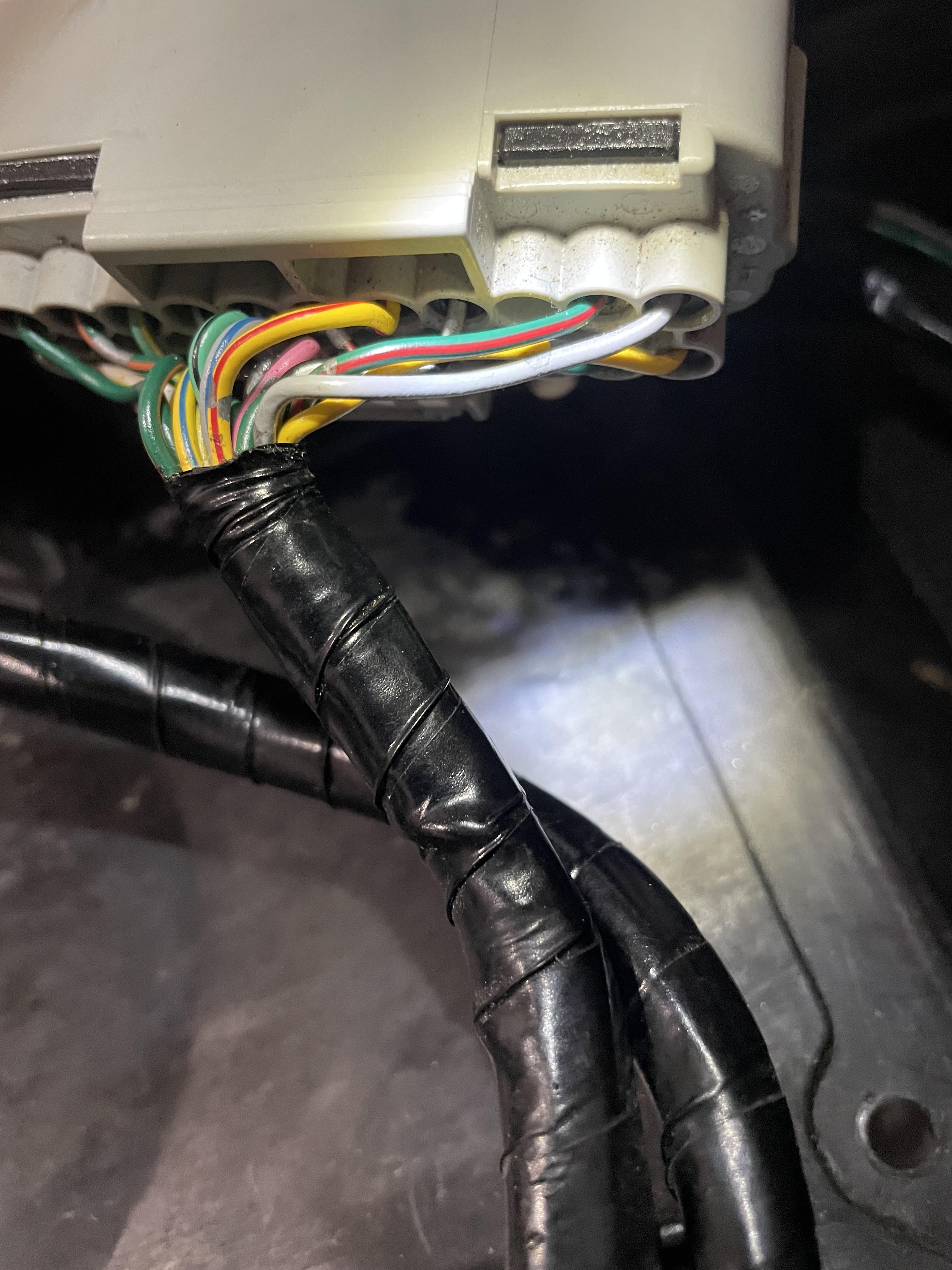
Good morning and thank you for your continued support. Yes I have continuity on the yellow brick Road.
-
Water Temp flashes 270 all the time with no codes
n3n3 replied to n3n3's topic in Fifth Generation VFR's
item 6 Yes I have already stated I have continuity in all 3 wires item 8 You are incorrect the wire is not green/blue it is blue with gray dashes item 9 I don't see that one Thanks for your help maybe it's just how you respond but you sound very condescending no reason for that. We are all fellow riders and Im trying to learn. Thanks again -
Water Temp flashes 270 all the time with no codes
n3n3 replied to n3n3's topic in Fifth Generation VFR's
Ok, so this is the correct wire diagram. Thanks thought I was going crazy! -
Water Temp flashes 270 all the time with no codes
n3n3 replied to n3n3's topic in Fifth Generation VFR's
I was told no and it doesn't appear to have been changed its a 2000 VFR800 USA model -
Water Temp flashes 270 all the time with no codes
n3n3 replied to n3n3's topic in Fifth Generation VFR's
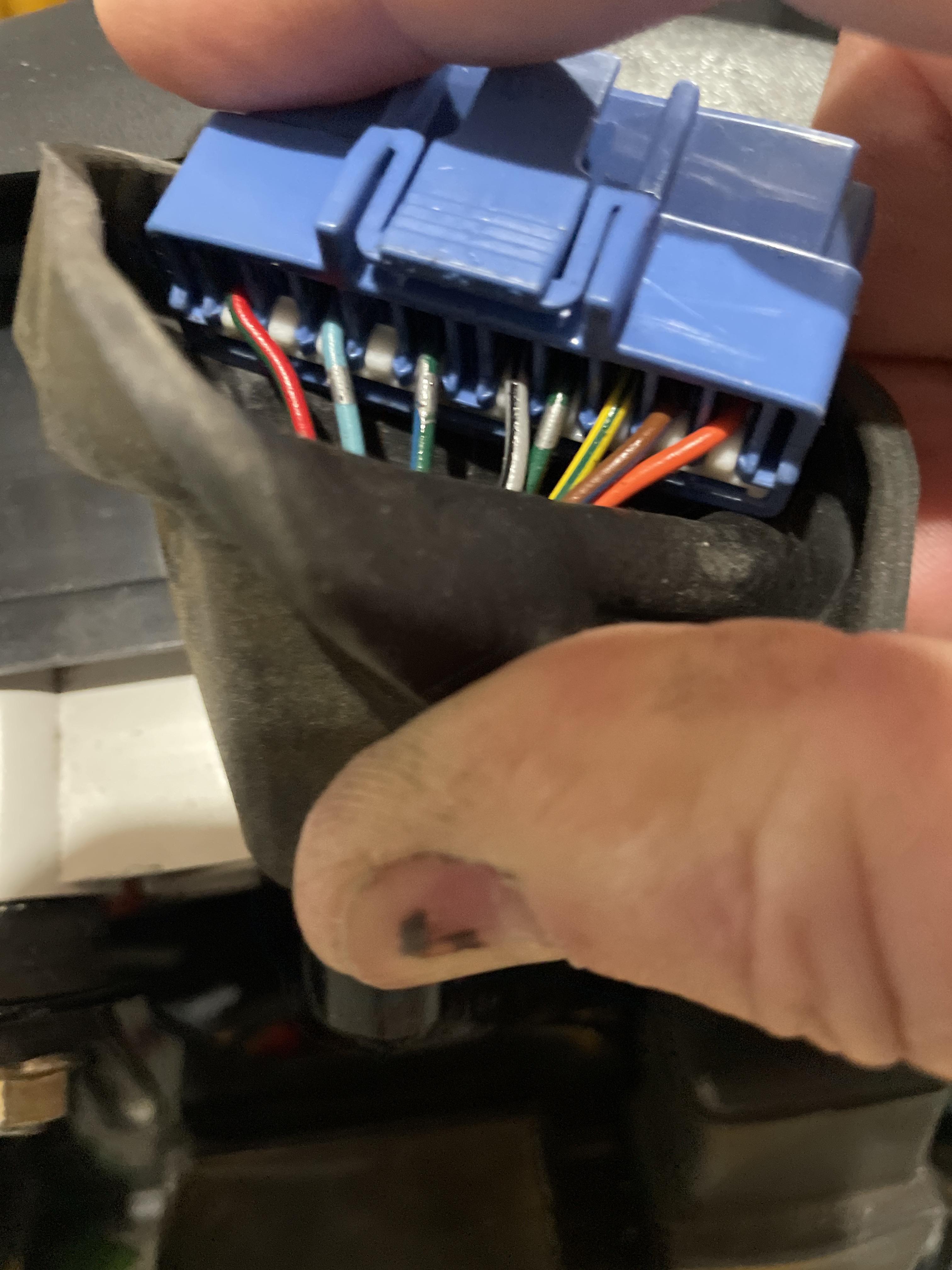
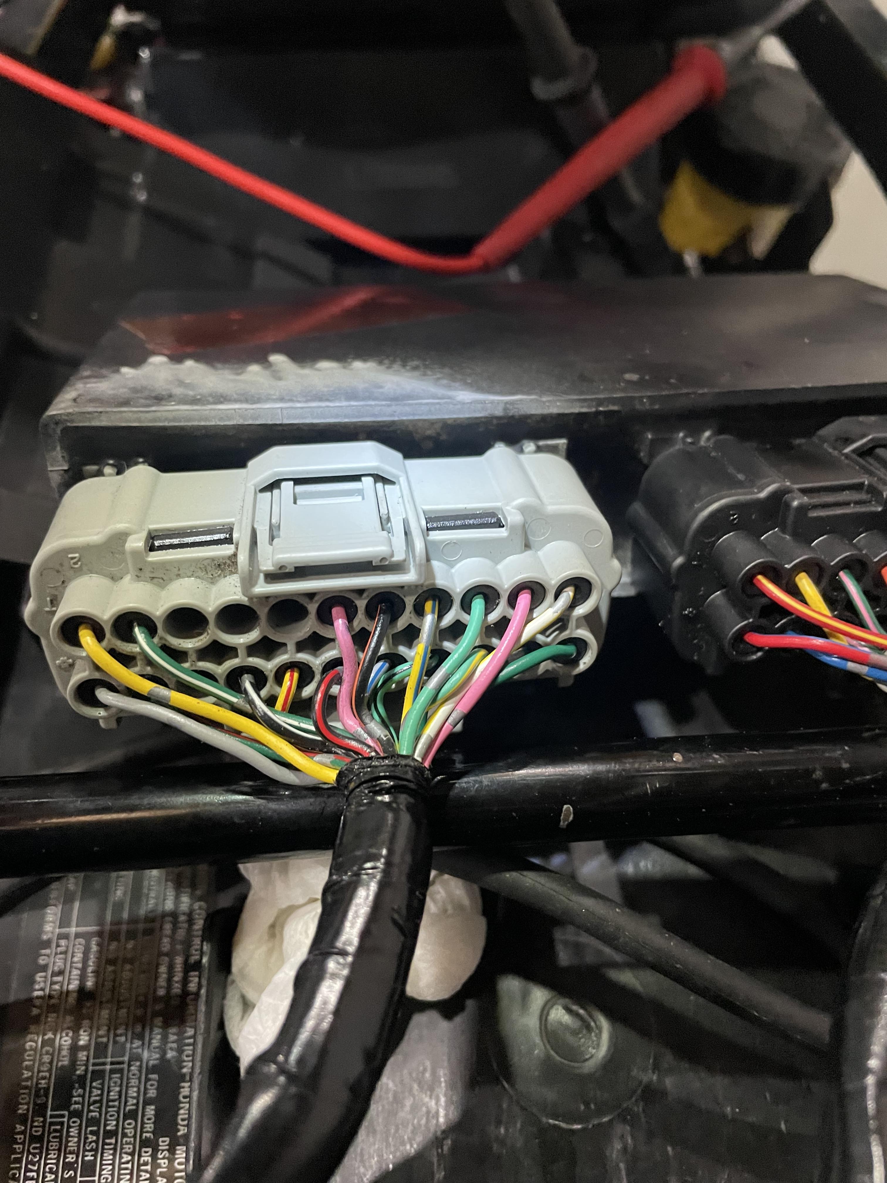
2nd picture 4th wire from the right yellow with blue stripe and 3rd picture wire Green with red stripe -
Water Temp flashes 270 all the time with no codes
n3n3 replied to n3n3's topic in Fifth Generation VFR's
Ok, it was a long day. To make things clear the ECT does have 3 wires but not the same color as the wire diagram I confirmed this by checking each wire for continuity point to point. I took a picture at the ECT this morning after it was reinstalled so you only see 2 out of the 3 wires. BLUE 10P wire is blue with gray dashes continuity to the instrument panel. I don't remember if the Green with a red line or the Yellow with the blue line had the 5 volts ECU G/R good continuity Y/B good continuity
-
Water Temp flashes 270 all the time with no codes
n3n3 replied to n3n3's topic in Fifth Generation VFR's
BLUE 10P wire is blue with gray dashes good continuity ECU G/Y good continuity Y/B good continuity Getting 5 volts -
Water Temp flashes 270 all the time with no codes
n3n3 replied to n3n3's topic in Fifth Generation VFR's
Yes, it has 3 wires to the ECT blue with gray dashes to the 10 blue plug to the instrument panel 3rd pin from the left. The other two are -
Water Temp flashes 270 all the time with no codes
n3n3 replied to n3n3's topic in Fifth Generation VFR's
The fan comes on when the engine runs for about 7 minutes just sitting in the driveway.