Leaderboard


Popular Content
Showing content with the highest reputation on 07/05/2025 in all areas
-
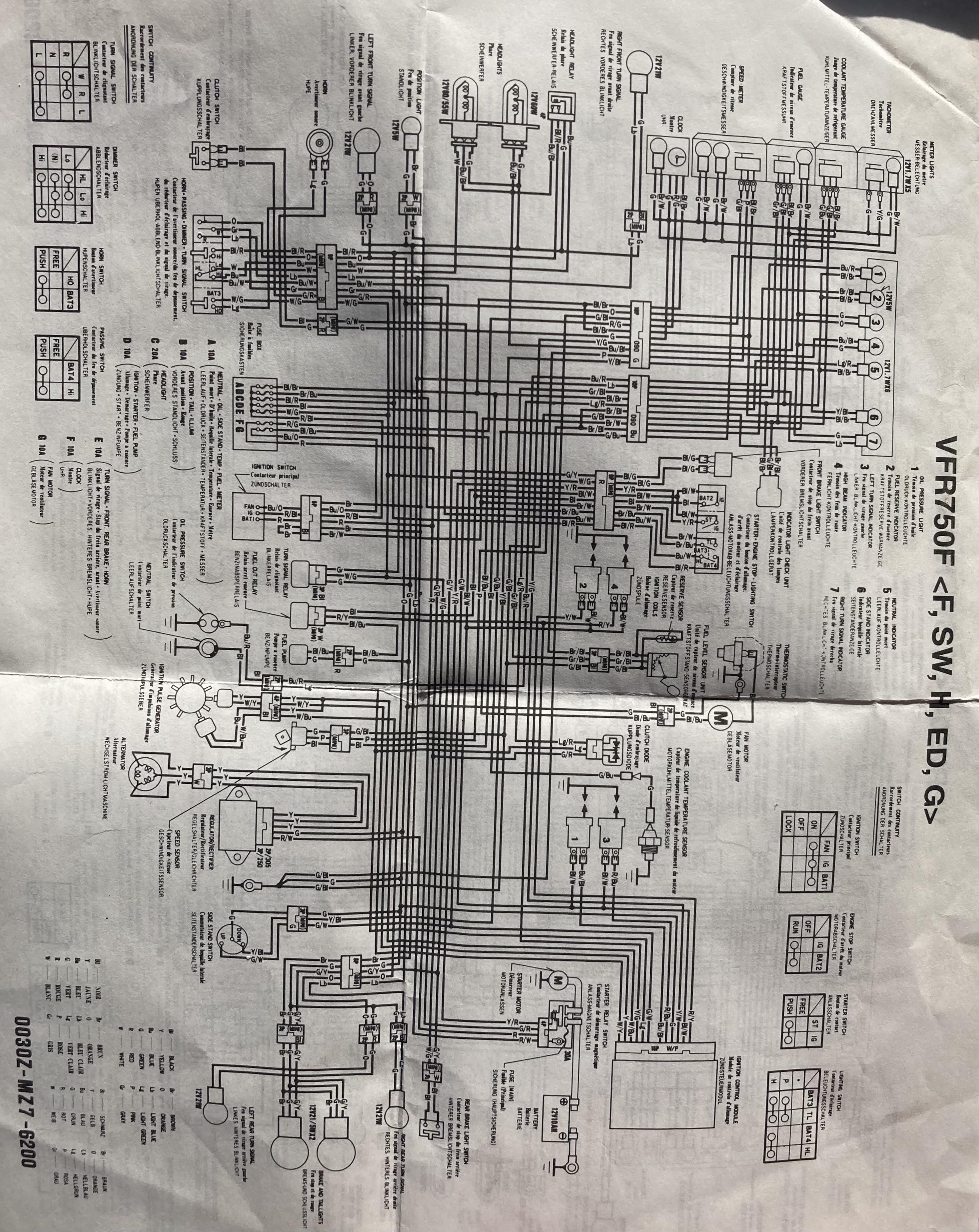
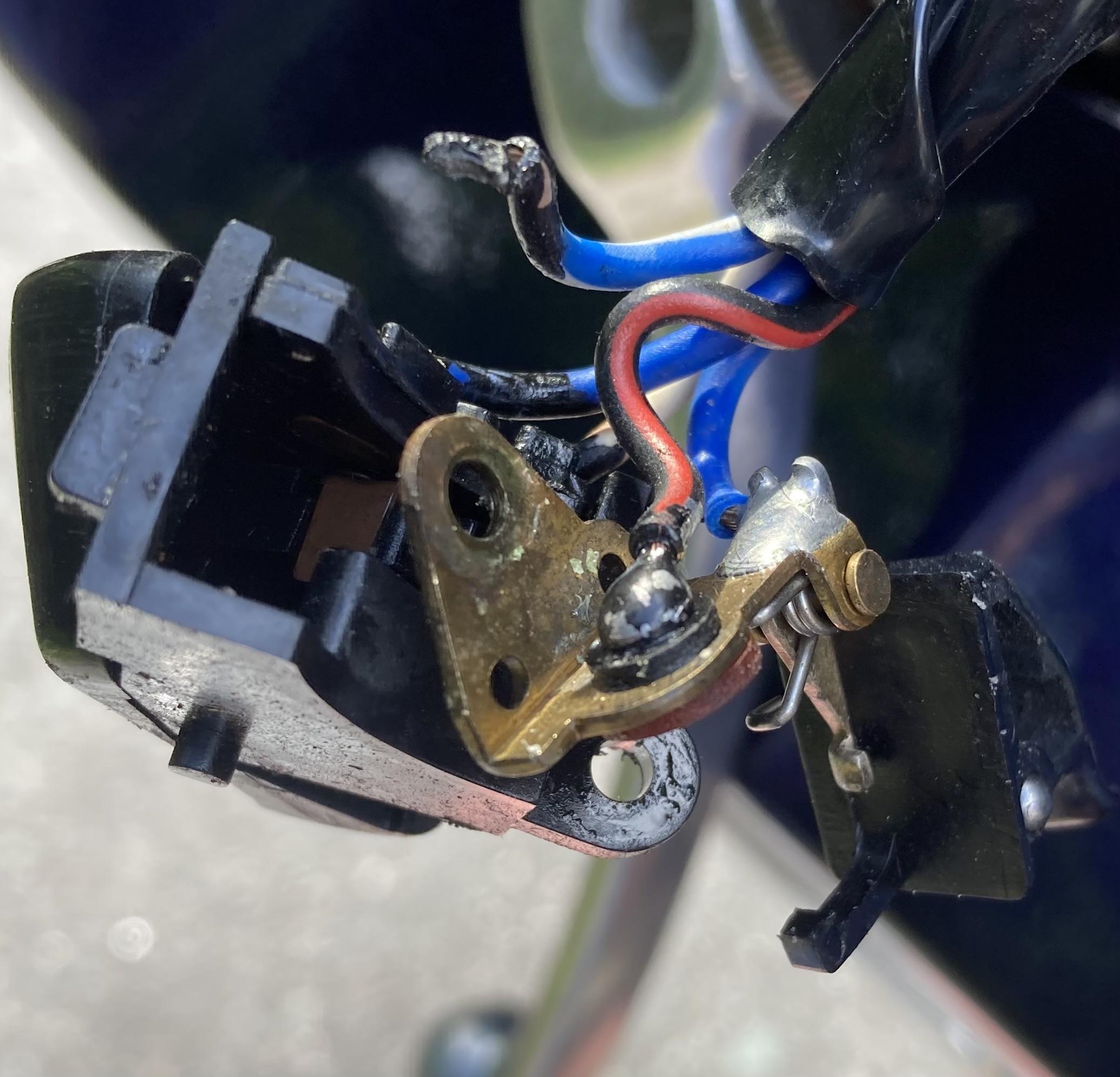
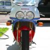
Hi, i just bought a -97 VFR750F, originally imported to Sweden from Germany. I got 4 circuit schemes with the bike so i had to figure out the correct one. The bike variant is VFR750FV - so the 'G' for Germany electrical scheme is valid. This means that there's only one light relay and no headlight circuit breaking on the start button on this bike. The problem with the bike is that headlight won't come on but passing button works so light relay and ground is probably OK. I checked wiring with the circuit scheme and a multimeter, started on the right switch assy since this is a known issue but all was good there. Then i opened the left switch assy and voila! The blue/white wire feeding the dimmer button switch has broken off. Seems to be a soldering hack job by one of the previous owners. I tried to see where it's supposed to be but it's cramped in there, hard to get access and solder it properly so i'll have to disassemble it.
 1 point
 -
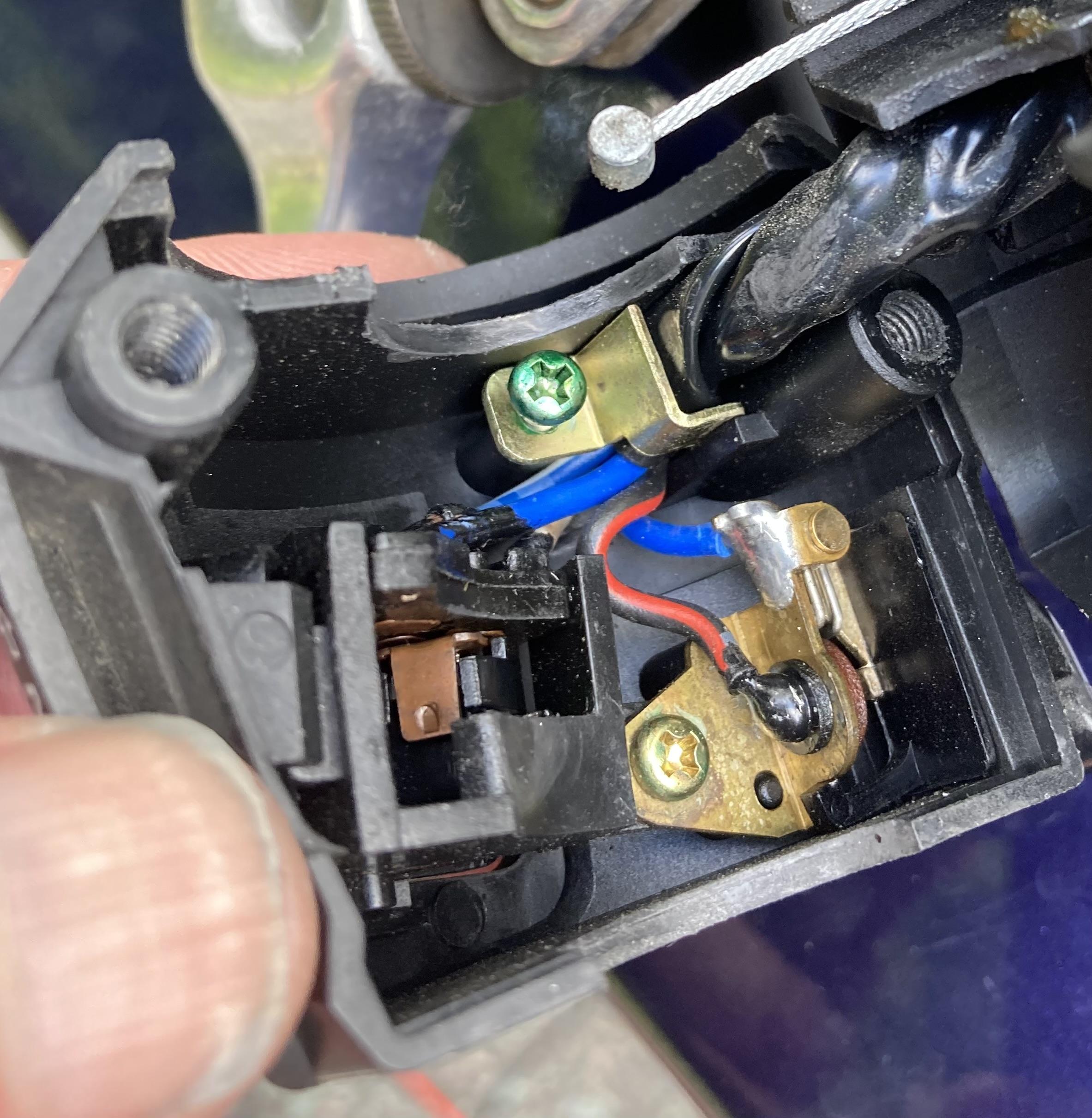
I got it back together after some trials, dimmer switch goes back first, then passing switch is threaded back into its' hole and both are secured by the same screw. It wasn't too bad even with my fat fingers 😄1 point
-
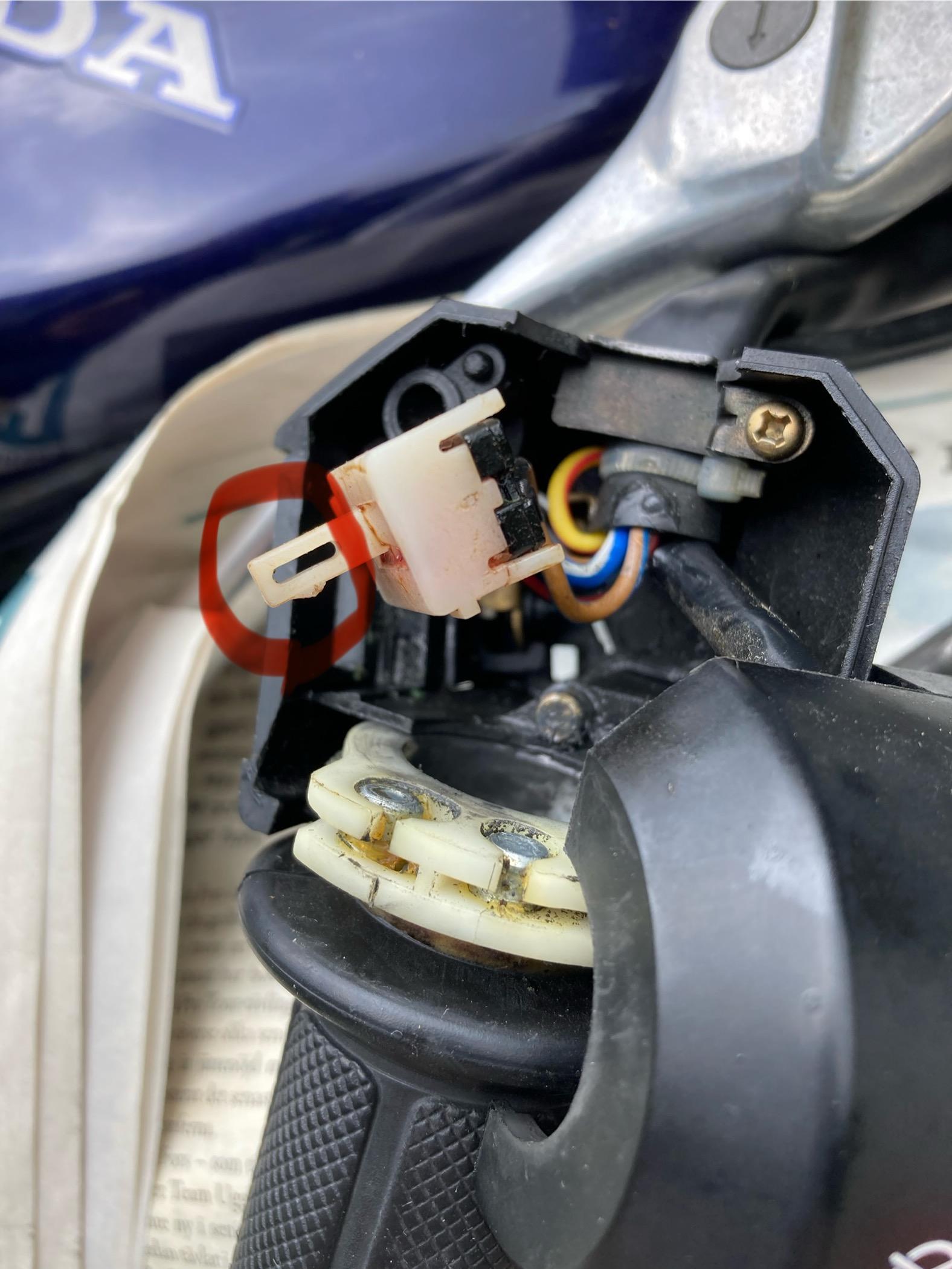
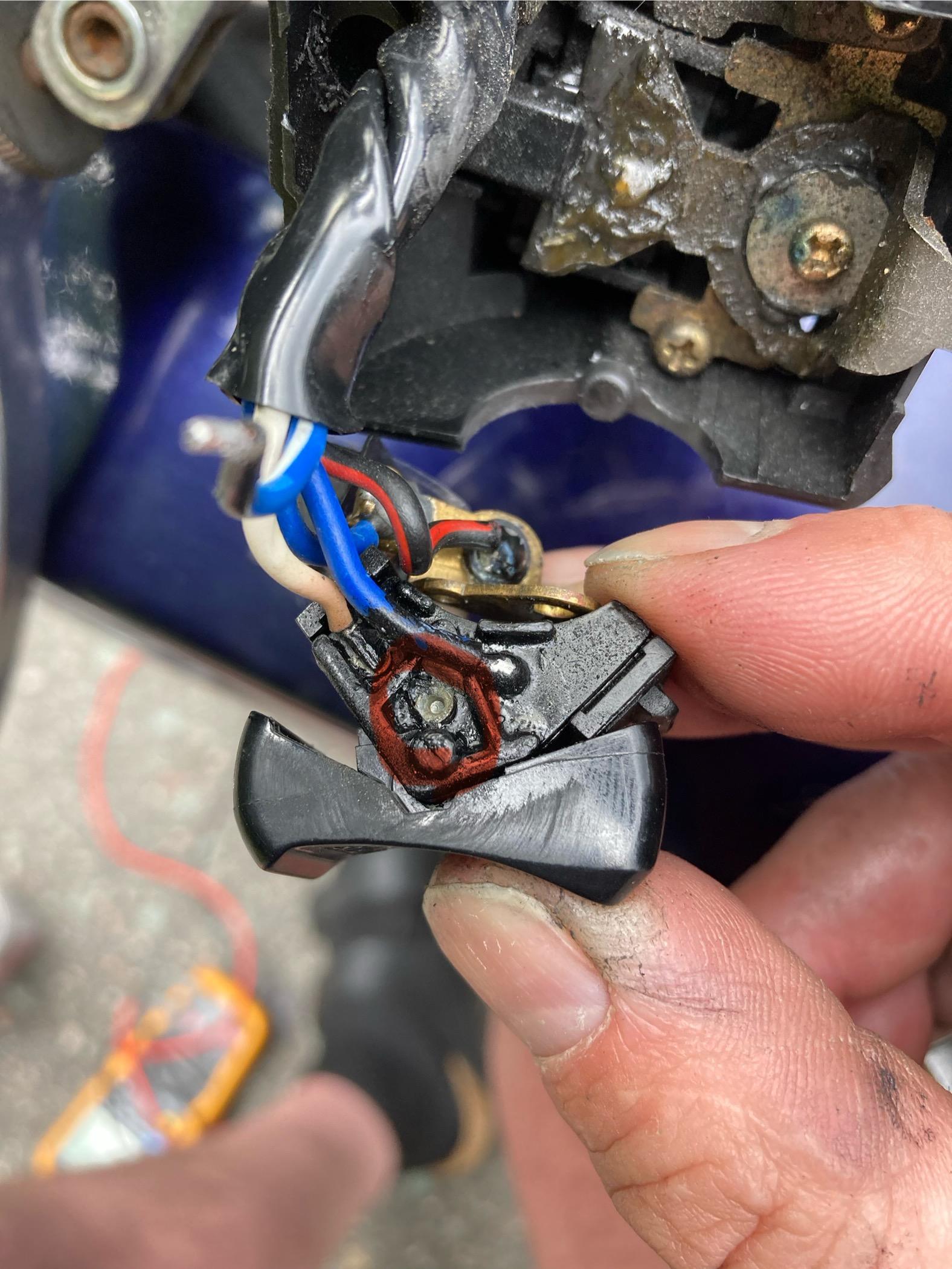
I found this video which describes the right hand switch disassembly and cleaning which could be needed if you have poor headlight connection. https://youtu.be/3_QMOKXJJmc?feature=shared I followed the video to be able to check the right switch assy. Some things weren't mentioned in the video: - to remove the switch assy from the bar i had to remove the brake lever. - i takes a large force to release the clipping feature that holds the right side light button on the switch body. You can see the why on the pic, snap feature is really stiff. Disassembly of the left side switch: Dimmer switch is just snapped in place and wasn't hard to get out after removing the cable strain relief and a fixation screw. you can see the soldering location for the blue/white feed wire which was broken off on my bike on below pic. This is what the left switch assy looked like before removing the dimmer switch: - i disassembled the passing button also to be able to remove the switch cover and gain better access for soldering. I struggled a bit during the removal so I am worried about getting it back together. Note: there's a spring and ball on the passing button for the tactile feel, this wants to escape and will be next to impossible to find if dropped. (Visible in lower right on pic)
1 point
-
.jpg.ce681c66c3d4a2a7aac284f44fda764c.jpg)
From the album: 5th gen tour 2025
1 point -
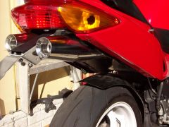
I don't see a "non-machine shop" way of solving this problem, unfortunately. From the installation instructions and the picture on the Scotts website, it looks like the damper mounting bracket is supposed to sit flush on top of the top clamp, but your VFR's top clamp is not flat. Assuming the raised surface would be able to adequately support that bracket, yes, a machinist should be able to turn an extended nut (with the groove) which would allow the damper mounting bracket to sit flush on top of the top clamp. You might also need to raise the tank flange bracket to match the new position of the top clamp bracket, but that should only require some alloy spacers of the correct thickness. (You might also ask Scotts why they didn't make one for this model, considering they've had 10+ years to do so...) For the new custom steering stem nut, I would probably choose stainless as the material, but I'm not the one who has to work it! Good luck. Ciao, JZH1 point
-
Cool Idea! I'm personally not sold on steering dampeners just yet, but more power to ya! If you figure this out it would be valuable to the forums for sure!1 point
-
1 point
-
From the album: 5th Gen Morph
1 point