tok tokkie
-
Posts
201 -
Joined
-
Last visited
Content Type
Forums
Profiles
Gallery
Blogs
Downloads
Events
Everything posted by tok tokkie
-
I have the greatest admination for what you are doing. Your forks are true to Norman Hossack in looks. That is the one weak point about the design - they don't look good to me. You had no choice; being constrained by the materials available to you (& Hossack in the original). Britten used carbon fibre & his forks looked great to me whereas the Confederate forks are similar but brutally ugly. The BMW cast aluminum are not pretty either. My favourite are the Vincent Girdraulic forged aluminum blades (not Hossack; a variation on conventional girder forks). I had a Vincent and stripped the stove enammeling off and polished up those aluminum blades - looked terrific. Like the Cyzsk (sp?). All of this is just comment & observation. Yours are going to look like what they are which is fabricated tubes. An honest design. Did you have trouble with distortion of the steering stem bearing seats after the welding?
-
7.6 kg without lower bearing race. http://www.vfrdiscussion.com/forum/index.p...c=16292&hl= The frame looks gorgeous. Waiting to see the forks, not sure about them.
-
I repeat what I asked before. Is there not room to fit a smallish tensioner pulley on the INSIDE of the BMW belt. What about close to the front pulley on the lower slack side of the belt? The belt will not be subject to reverse bending. You are so close to the allowable center distance that the tensioner will not need to deflect the belt much and therefore there will be very little wrap of the belt around the pulley. The pulley will have to be toothed.
-
I really wanted to go down this route when I had a VFR so have followed every posting on this topic. Bummer man that it didn't work out as you hoped. Is it impossible to add a small tensioner running on the lower slack side of the BMW belt on the INSIDE of the belt? Obviously it will have to be a toothed pulley. Your observation that the BMW belt is soft would not apply to the inner toothed side since that is intended to run over pulleys. There would be very little wrap around the tensioner pulley since you are already so close to the allowable range. It would, as Fallzboater, & other, say compensate for the changing center distance as the wheel moves. The 30 + 76 combination gives a ratio of 2.533 which is very close to the original 2.529 that the standard 17 + 43 gives so it really would be great if you could make it work. I admire your manual milling work tremendously.
-
Is the front suspension shock unit going to live down there? That is where John Britten fitted his rear suspension shock unit. All knowledgeable motorcyclists will immediately recognise who you are tipping your hat to there. If it is as it looks how are you going to invert displacement so upward deflection of the wheel results in compression of the shock unit? What are your intentions about a radiator? Looks like plenty of space between the shock & engine for a conventional superbike radiator.
-
Makes it look like wheelbarrow in my opinion. Each to his own.
-
On the FFE graph of anti-dive percentage: 1. It changes from pro-dive to anti-dive at about 35mm wheel deflection. Is 0 wheel deflection when forks are fully extended (ie front wheel just about airborne)? If so then 35mm is about normal static pre-load so it will be anti-dive under all normal conditions. 2. What does the curve for normal tele forks look like. I appreciate it is pro-dive all the way but it must be progressively less as the spring loads up I would expect.
-
Aegis should be iges I think. It is an industry standard for exporting & importing between different cad.cam programs. I just want the wireframe drawing (no solids thanks) so I can re-create it in my Cimatron & generate the toolpaths from there. Using other peoples g-code is really not an option I would like to explore. A dxf file should be fine - I can have it plotted and then re-create it myself. I will pm my e-mail to you. I take it there is no rush about this thing.
-
This is good. Very good. Those cad plots wrapped around the tubes - do you plot the developed shape, tape it to the tube then grind for accurate fit-up? Nice move. Is that going to be a pivoted tail section? Two crosswise tubes next to each other. I had a Vincent (Comet) so have experienced an articulated tail section - it is not noticeable at all with the Vincent geometry. I see the full scale plot of the front end legs. I am retired & have a cnc machining center in my workshop (Haas VF2). I would be happy to machine some rearsets for you. Send me a plot file and an aegis (spelling?). I run Cimatron 9 CAD/CAM but my pre-release version is very flaky about importing aegis (sp?) hence the request for plot file. I won't charge you - I would feel honoured to be associated with this project (& also the ToroCharger project) Check my gallery for shots of the upper triple I made - plus some informative disasters. You have not blanked off the throttle bodies. Do it now.
-
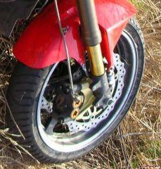
 Stop teasing. Tell us about it. Yammie calipers & Phantom tells me those are Ohlins forks. Come on 'fess up because we need to know.
 -
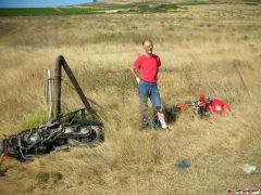
Thanks for the link. I am going on long solo tours on back roads and have been puzzled about a tripod for the bike.
-
RC51 front end on 5th gen
-
-
From the album: RC51
© ©vfdiscussion.com
-
Very nice! I could do with a milling machine! do you think I can borrow yours? lol :rolleyes: Need to get the hossack front bearing holders made. Using small bike wheel bearings - hopfully they will be up to the job! have you any links to your franenviffer? :thumbsup: Yes. But don't follow my example. http://www.vfrdiscussion.com/forum/index.p...f+frankenviffer
-
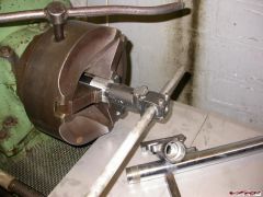
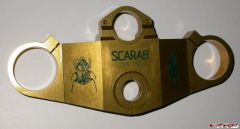
scarab 13.jpg I have used the Scarab name too. Triple I made for my Frankenviffer project.
-
Earlier I showed the track as it is shown on the Zumo. This is how the Zumo depicts your actual track (not planned route) as I left Agua Caliente on a back country road towards Borrego. As I said before you can leave this track on the Zumo if you like – maybe you are retracing your route for instance. Below is an example of what it looks like when you download the tracks (actually where you rode) from a trip to your PC. They load right into Mapsource and you can really dissect each trip. Here is the first leg of my return trip from Borrego to San Diego. The track record includes 46 points of information for the 2.6 miles from my camp site to the gas station in Borrego, which was my first stop. About 8 different pieces of info are collected for each point i.e. altitude, direction, coordinates, time, speed, etc. You could play with this for a long time to include making altitude profiles, avg speeds for legs and the list goes on. In the first picture the color of the unused roads is not very distinct from the background: 1. Is it possible to select other color combinations? 2. Have you found it difficult to see under any cirumstances?
-
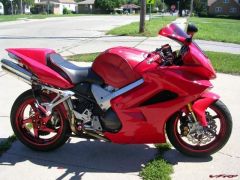
 It will look good with gold socks on the front.
 -
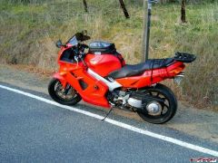 Some shots have standard can others have under-tail cans.
 -
. All Done
-
The Ride I had worked late into the afternoon and was taking an unusual route home because it would give me a better chance to feel the improvements. First thing I found was the front brakes are pathetic – hardly any bite at all; much inferior to the linked brakes of the VFR. I stopped after 15km and saw that the disks were covered in oil; in fact it was brake fluid which had leaked out in the trip from Edmonton to Cape Town. I also found the rear rotor to be blistering hot. That turned out to be the inner brake pad being hung up on the anti-squeal spring plate. I got new brake pads, cleaned the rotors and rubbed the glaze off with 320 grit wet & dry. Bled the brakes – what a pleasure compared to LBS. With that done I went for a blast in the mountains. A 40 km slab out to them. First pass is Du Toit’s Kloof on the Cape Town to Johannesburg road. (Kloof is an Afrikaans word meaning valley or gorge.) Now there is a tunnel through the mountain so the pass is very little used. Nice flowing curves. I ran up quickly & down the other side bedding the new pads in. They soon were biting really nicely. Then along the Slanghoek (Snake Bend) valley to Baine’s Kloof. This (Slanghoek) is a very lightly used road serving the local farming community but the road is in excellent condition. There is a big sweeper on this road that I know well. I was really building confidence in the new forks by now so whistled round even faster than usual and was delighted at how easy it was to adjust my line and accurately track the center line. The suspension action has been a revelation to me. I have set the suspension just as zRoyz recommended with 7.5 weight oil with 120mm air gap. I could not set the sag correctly – had to screw the caps totally down & that gave me a hard ride on my way home the first day so I backed it out by 2 rings. Part of the problem may have been that I set it by myself with the bike on my paddock stand which pitches the bike forwards quite a lot adding to the static sag. I have a zip-tie on the slider & see that I have been using most of the fork travel. Veefer described it best - poink over the bumps. I am absolutely delighted with the improvements to the ride; way above my expectations. Now to get a Wilbers but first some more fine tuning of what I have. I have a set of CBR 600 springs which are about the same 7.5kg/mm rating as the standard VFR springs (RC51 springs are 9 kg/mm). But I expect to go back to the RC51 springs judging by what the zip-ties are showing. Next is back over Baine’s Kloof. This is very different to Du Toit’s; it was opened in 1853 and is 30 km long going up a steep gorge on the east side (the side I now came to) and down the flank of the mountain on the west. The eastern side is very twisty and cut into the side of the gorge while the west is far more flowing but narrow compared to Du Toit’s. This road has hardly changed since it was built for horse (& cattle) drawn vehicles besides being tarred. Trying to run it fast is not rewarding as it is squirt then jam on the brakes all the way up. Much nicer is to slow down and try and use the brakes very little; just flow your way up smoothly. Here the new forks excelled and I was scraping my boots time and again (I have only touched the feelers on a track day and when hitting a bump on a corner on the road). This road links two small towns so there is very little traffic but it is my favorite because it is so picturesque. Then another 30 k slab back home. There is one section on this road that has really bad bumps which unsettled the VFR previously & I can’t even remember how the new forks dealt with it – must have just ironed them out so that I didn’t even notice them. I then meet up with my evening ride route at Durbanville. Some rolling hills with a road winding down. Another sweeper I know well that I ran 10kph faster than usual as I now had so much confidence in these new forks. Then I caught up with cages at the twisty bit. Last cage moved over indicating he expected me to run around the outside (this is very common here – there is no aggravation between bikes & cars) which I did. As soon as I could see the road clear ahead I blasted past the leading two cars. What happened next I can only re-construct because I have no memory. I believe I dabbed on front brakes as I had accelerated to be running faster than usual in overtaking but was caught out by the wonderful new front brakes (and lack of linked brakes) and locked the wheel & low-sided. I slid across the road & crashed into the side of a car coming the other way but the bike hit the front of the car and that is the end of that. I was never going to sell that bike. The VFR is the perfect bike in my opinion & I have so enjoyed customizing it to make it really my personal statement. Now I have destroyed it. If the bike & I had swapped positions during this crash then I would be in a worse condition than RiotGirl. It is mostly luck what happens during a crash. I have been very lucky in many ways. I have to discipline myself; I am too irresponsible to ride a bike as capable as the VFR. I thought it was going to be my last bike but I now think I will get a – whisper voice here please as I am ashamed to admit this - BMW F650 Dakar and go riding in the arid areas of the country (Gramadoelas = boondocks) on dirt roads. Long trips – days - weeks. There is an excellent website ChainGang (www.f650.com) where I expect to be hanging out. I have always thought of BMWs as boring, dull, sensible bikes for poncy, posing yuppies. They certainly have not attracted me but recently their styling has improved and they are currently introducing more innovations than any other manufacturer (tele-lever, para-lever and now the Hotchkiss front end = duo lever). From a personal image point of view I would much rather own a Yamaha XT660 or Kawasaki KLR but they are not available with ABS. The F650 is available with ABS and that is the deciding factor to me. When I confessed that I am thinking of getting a dual sport bike my wife said 'Get two & I'll join you". Don't know what to make of that - mommy wanting to keep an eye on me? ABS = All Bikes Should (Scootr)
-
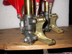
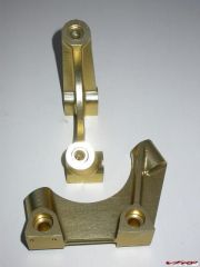
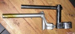
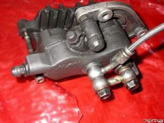
Anodising I had the brake adapters and upper triple anodized bright gold. I also wanted the compression adjuster pots that sit just above the axle anodized but the anodisers warned that cast aluminium usually turns out grey. The 6082 of the brake adapters turned out a much paler colour than the 7075 of the triple. If I make new fork bottoms I will use 7075 to get that same dark gold colour. The torx stars on the R1 calipers is slightly darker than the upper triple so I expect it too is 7075. I have decided on an Iberian theme to the colour of this bike. I asked the technical person at the anodisers about the problems with anodizing cast aluminium & he said that there are 2 alloys which anodize ok & the rest all give a grey colour. It is easy to tell simply by dipping the component in the caustic bath. My thoughts are to polish the SSA and hub and anodize them gold so I will take them off some day & have him test them before I go any further with that idea. Besides Spain there is Portugal on the Iberian peninsular which has a green & red flag so I chose green paint to emphasis the engraving. I bought model aircraft enamel paint and scraped off the excess with a Stanley knife blade. I engraved the beetle on one of the brake adapters but did not colour it because the adapters do not have a smooth finish. They were finish machined with a 6mm ball-nose cutter with a 1mm step over between passes so the surface is rippled and it would not be possible to scrape off the excess paint. Rear Brake Having lost the linked brakes it is necessary to modify the plumbing to the rear brake. The caliper has three pistons; the outer two are activated by the rear brake pedal; the middle one is activated by the front brake. I got two banjo connectors; cut the spouts to size and silver soldered a small piece of stainless steel instrumentation tubing over the spouts. I threaded a piece of copper flex through the spouts so that the flux or silver solder did not block the spouts. I had to use three washers to get the double banjo level. I have used a 16mm CBR rear brake master. The brake is very powerful – easy to lock up the back wheel. Tread carefully. Banjo connector.jpg Front Fender. Safe-T got me a CBR front fender. I made a little bracket out of stainless tube for the back mounting screw. It is screwed to the brake caliper adapters with two little M4 cap screws. Because the forks are now swapped left to right I also had to make small spacers for the front bolts (lugs are further from center-line with forks reversed. Bars I made bars from stainless steel. Verticals are 32mm. The forks are 10mm closer to the rider because of the lower offset of the CBR & RC51 triples. The vertical pipe is 60 degrees back from being straight across the bike (looking directly down at the top of the triple) so that brings the bars back another 36mm. (fork is 50mm, pipe is 32mm so radius is 25+16=41; 41sin(60)=36). The anhedral is 3.6 degrees – that is the angle of the hole through the 32mm vertical tube but you end up with 15 degrees when mounted on the bike because of the 25.5 degree rake of the forks. That 15 degrees compares to the 17 degrees of the standard bars.. The bars themselves are swept back 20 degrees (but that is adjustable as there is no safety pin). The center of the 22mm bars end up 124mm above the triple. I cut the bars for a span about the same as the originals. The bar clamp has 3 M5 cap screws. No need for a safety pin. They may look a bit fugly but I am delighted with the ride. They have really taken the weight right off my wrists and I sit up in a steady breeze behind my Puig double bubble. Very comfy ride. Bars 1.jpg
-
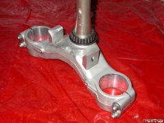
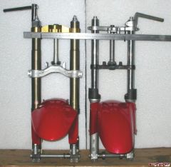
Fork Lengths I made a sleeve for the VFR axle to fit the RC51 fork (RC51 axle is 22mm vs. VFR 20mm) so I could accurately measure the difference in fork lengths. The RC51 forks are 16.6mm shorter than the 5th gen VFR forks. I measured the difference between the tops of the full diameter portions of the fork caps – in other words the highest place where the bars could be mounted. Vfrcapn posted last week photos of SP1 & SP2 forks and the SP2 forks are 23mm shorter than the SP1. Swiffer listed RC51 forks as being 32mm shorter than VFR (but that was 4th gen I believe). Veefer800Canuck reported that his front end ended up 10mm lower when he did the conversion. I also noticed from the pictures vfrcapn posted that the SP2 seems to have less fork travel than the SP1 My RC51 forks were 16.6mm shorter than my VFR forks (5th gen) RC51 & VFR together 1.jpg The ruler is clamped to the surface the steering lock bolts to. It joins two surfaces at the same height on each front end. I wanted to get the distance from the bottom of the steering neck on the frame to the axle as close as possible to what it was with the stock forks. I measured that at 521mm with the forks fully extended. That was my target. measur.jpg The VFR bars have a little safety circlip above them. That makes the top of the fork stick out 6mm above the bars. My home-made bars can be clamped right at the top of the forks so I save that 6.0mm Distance saved by mounting bars right at top of forks 6.0mm Thus ‘shortness’ left to compensate 10.6mm I made my top triple effectively the same geometry as the CBR. I very carefully measured the distance from the upper surface (at the bar clamp area) to a reference point on the frame. The top of the CBR triple is 13.5mm lower than the VFR triple. Thus the axle would be 2.9mm FURTHER from the frame with my combination compared to the original. CBR triple upper surface at bar clamp area is 13.5mm lower than VFR triple. Adding the distance gained the axle can be 3mm further from the frame using RC51 forks & CBR959 upper triple if the bars are mounted flush with the tops of the fork caps. (In fact it is slightly more because of the 10mm less offset of the RC51 triples I got 6mm when I measured) The fork travel of VFR is 120mm The fork travel of RC51 is 129.5mm The RC51 triples bring the wheel back by 10mm (steering stem to fork center) which reduces the wheelbase. The steering rake is 25.5 degrees on the VFR. You end up with 11mm increased trail which makes the bike more stable and slower to tip into a bend. To overcome that steering slowness Swiffer, zRoyz and others drop the triples down the forks.
-
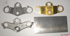
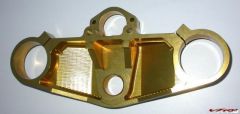
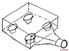
Top Triple. Safe-T had got me a CBR 959 upper triple. It had been sand blasted and was not very pretty. That did not worry me at all as it was always my intention to make my own take on a Vortex top triple. All I needed the triple for was measurements. The forks centers are: 107 VFR 114 RC51 The forks are offset 40 VFR 30 RC51 in front of the steering stem. A gull wing aircraft has wings that rise steeply from the fuselage then flatten out. The CBR 959 upper triple is a reverse gull wing or upside down gull wing. The RC51 forks are shorter than the VFR forks. Swiffer gave a table of data for various front ends. That lists the RC51 forks as being 32mm shorter than VFR. I have measured mine and get a different length which I discuss in another post on this thread. To keep the front end geometry as close to original as possible we use the CBR upper triple and not the RC51 because of the gull wing shape of the CBR. The difference in height between the top at the steering stem and the top at the forks is not the amount of forks will be lowered – because the thickness of the center boss which gets clamped onto the bearing nut and how deeply the flat on the underside of the triple is recessed (the flat sits on top of the steering stem lock nuts). I measured between the upper surface at the forks and a reference point on the frame and the CBR triple lowers the forks 13.5mm compared to the VFR triples. I measured up the CBR triple and made a CAD/CAM model with identical relationships between all the components (height difference center & sides, thickness of boss at steering stem, distance between forks, distance forks are ahead of the steering stem and all the dimensions for the lock so the steering lock will work.). The VFR and CBR triples have subtle curves but I chose to use simple straight lines. This is purely an aesthetic consideration and I like the honesty and integrity of direct lines connecting the elements. I chose to use two M6 cap screws for clamping also for aesthetic reasons and I positioned them to minimize the number of edges it creates. When they are fully clamped the slit is perfectly closed – that was just fortune; not by design – but it looks good to me. The engraving of the dung beetle was just for fun and is in complete contrast to the brutal straight lines that I used for the shape. Years ago I wrote a freeware program called Scan2CNC which reads in a 9-pin dot matrix graphics print file and converts it to CNC G-code. That was in the days of DOS and was written in a proprietary business database language called Clarion I used aluminium grade 7075 T6 which is quite a bit stronger than the 6082 that I used for the brake adapters. 7075 is not available in Cape Town, it had to come from Johannesburg. triples 1.jpg Weights VFR 600g CBR 500g Scarab 640g Billet 5900g I could have machined more out to get it closer to 500g. You don’t know until you have finished (CAD/CAM can calculate it for you but then you have to model it very accurately with no holes in the surfaces – which I did not do) scarab 13.jpg . scarab 4.jpg
-
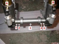
Axle. VFR axle is 20mm. RC51 axle is 22mm. Because I have used the VFR wheel in the RC51 forks I was not able to properly fit the wheel to the new forks to check dimensions; you have to change wheel bearings and it is unkind to knock a bearing out by hitting on the inner race . I made thin plastic bushes so I could use the VFR axle in the RC51 forks. When I came to swap the forks I found the wheel bearings are offset 30.9 mm on the right but only 24.35 on the left. The wheel hub of the VFR is not symmetrical. Axle 2.jpg In the photo which is taken from the front fork A is on the right side of the bike but would be on the left on a RC51. I had the RC51 axle together with the two spacers. In the picture: 1 9.8mm new spacer 2 16.5mm original RC51 spacer 3 ?? original VFR bearing spacer 4 9.1mm original RC51 spacer 5 15.25 new spacer I chose to not make single spacers for each side because I have a lathe that is a bit older than myself (62) which does not give a really good surface finish. The original bushes have a lovely finish and these run under the bearing dust seals. The axle fits in through fork A. Spacer 5 presses up against the inside of fork B. The axle nut is on the outside of fork B. To center the wheel in the forks it is the size of 4 & 5 which do that. That determines the size of #5. Spacers 2 & 1 determine how far the axle goes through fork B. I chose to make the little bit of the shoulder section of the axle between fork A & spacer 1 the same as the amount the axle ended up short of the outside of fork B (about 4.6mm). That determines the size of #1. So the total distance from the fork A to the bearing is 9.8+16.5+4.6=30.9 The total distance from fork B to the bearing is 9.1+15.25=24.35 Steering Stops Veefer used two cap screws as steering stops. I have used two pieces of aluminium screwed to the triple. The anhedral of the gull-wing (strictly inverted gull-wing) is 30 degrees. I machined the aluminium at 30 degrees and drilled and tapped M8 holes perpendicular positioned starting at the inner edge and breaking out on the outer side. I made a spacer out of scrap steel the same as the distance between the stops on the VFR lower triple. I clamped the two stops to this and then clamped that assembly to the triple fitted to the bike. I was then able to position everything and scribe the triple through the M8 threaded hole. Take it all off and drill 8.5 holes at the marked position and fit back. I had to file a bit at the front to clear the instrument panel bracketry. They actually worked out the correct size but I could easily have machined more off the back surface if they had been too long. Vfrcapn shows a nice alternative in his recent Frankenviffer thread. steering stops.jpg
-
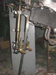
Front Wheel I decided to stick with the VFR front wheel. You have to get RC51 front wheel bearings because the RC51 axle is 22mm diameter whereas the VFR is 20mm. The 47x22x12 (check, is it 14?) bearing used in the RC51 is special and only available from Honda or possibly Kawasaki but you will not get this size from a Bearing Distributor. Sticking with the VFR wheel saved me a lot of money as RC51s are not common here and I would be very unlikely to find a wheel here. Safe-T sent me all the components and the freight cost for the wheel would have added a lot to the cost of this project. Now I could also stick with my brake rotors, get whatever calipers I choose and make adapters to fit the calipers to the RC51 forks so they matched up to my existing wheel & rotors. Front wheel.jpg Brake Caliper mounts. Safe-T advised that the standard RC51 calipers don’t line up with the VFR rotors. As I was going to have to fabricate my own adapters to align the calipers to the rotors I could choose whichever calipers I prefer. I like the Yamaha R1 monoblock radial calipers with the two Torx stars on them. Safe-T found some with gold starts on eBay which suited me well as I am aiming for a red & gold bike – colors of the Spanish flag; though my heritage is Provencal France. I made plastic bushes for the VFR axle to fit into the RC51 forks and fitted my wheel to the forks and measured up. I cut rudimentary adapters from blocks of nylon (cast nylon machines beautifully) and checked it all out. It confirmed my measurements. I then modeled better looking adapters in my CAD/CAM program and machined the adapters from billet 6082 T6 aluminium. I had found that the best thing to do was swap the forks left to right as then the adapters fitted in very well. I later on found that my measurements were not quite right and that the right caliper needs to be shifted 2mm closer to the middle. I have not examined it all to understand where the mistake comes from but I suspect that the rotors on the VFR wheel are not equally spaced from the center-line. I know the hubs are quite different each side – see my axle spacer topic. bracket 1.jpg Notice the twist to the adapters. Fitted brake adapters 2.jpg