


MooseMoose
-
Posts
245 -
Joined
-
Last visited
-
Days Won
9
Content Type
Forums
Profiles
Gallery
Blogs
Downloads
Events
Posts posted by MooseMoose
-
-
Haven't tried RBo2 Active unchecked in this configuration. That's specifically supposed to be checked if you have stock sensors, according to rapidbike. I could flip it off and see what happens, but I don't know what to expect. Does the stock signal still pass the harness without RBo2 Active? And if so, will I throw the codes and go into the failure-rich map? Might be interesting to see. But I'm sure I won't be running it RBo2 Active with the sensors connected for long.
I did try it before I got the MTB module and it most definitely didn't work well with stock sensors connected. Same problem, but worse as it takes a lot longer to correct the bad readings. That was why the eliminators went back in after I sold the PCIII, and it worked much better with eliminators.
Basically, it works properly with not active and eliminators so that's what I ran most of the time, before and after I got MTB. I just decided to try it hooked to the stock sensors since I was in there with the fresh pipes, and I have my MAP sensor error fixed, so I am theoretically in the best possible state for things to be tested since I got the bike.
-
Of course I do. I did that long before the rapidbike, actually, but the rapidbike literally will not work properly with the Pair enabled.
Why do you ask?
-
RapidBike Users
I have a Rapidbike Racing with a single MTB. I think it is using the older 4.2 sensor, not the newer one.
Backstory (Skip this if you don't care)
====
For a long time I have been running it with resistors in instead of connecting the stock sensors. I did this for a few reasons, the first being that my Delkevic headers occasionally leaked after big temperature swings, so when they got super hot I could sometimes get fussy correction, which I controlled by limiting the max correction that could be applied. And the second, big, reason was that I had a horrible experience with the lean mode as the bike would go super lean at constant RPM while cruising. I'd add throttle, it'd get slower, I'd add more throttle, then finally when I hit 5% throttle it would switch out of lean mode and surge. REALLY annoying I couldn't just hold a steady speed and stay there.
Some of the problems might have been traced back to an error code I was getting my MAP sensor, which sent the bike into "Default mode" for fueling. This is richer than normal and makes for a huge difference from lean cruise to normal. However I didn't figure this out until after I'd already started using O2 eliminators and then the rapidbike. I fixed that problem, and the new headers do not leak, ever, from what I can tell. So I decided to try connecting and RBo2 Active to see how it worked.
====
Current Setup:
- I have both stock sensors in and connected.
- I am running the single sensor MTB
- My advance map is zeroed out completely
- RBo2 Active is checked
Results:
- RBo2 Active does not seem to account for the change to lean fueling. The bike will go into lean mode, and still surge annoyingly
- The MTB will completely pork the map after cruising between 5000 and 6500 rpm.
- I hate the Honda engineer who came up with this lean mode at steady RPM thing with an abiding passion
The end result is that, if you cruise along at say 5500rpm for a little while the bike will eventually run normally, but then when you grab a handful getting on the freeway or something, there will be a monstrous hole in the powerband between 5 and 6K. A couple of runs accelerating through that range will restore full power again.
My basic assumption is that the maps are chasing the lean. It never reaches real runaway level, but it does make for a substantial correction on both sides before it stabilizes and when you're using it more dynamically you can get bad results. On rare instances, it'll pop and backfire on throttle shutoff. Basically, if you cruise, then accelerate (taking it out of cruise mode), then roll off. This tells me it is going too rich as, when it's running nicely and I'm going up and down the RPM range it never sputters or pops.
So, I don't buy that RBo2 Active is a valid solution on 00/01 VFRs. My next experiment will be to put resistors back in and unplug the stock sensors, counting on the leakless nature of the new headers to make a much better map.
Overall, when I haven't been cruising for a long time beforehand, the acceleration is glass smooth and noticeably stronger above 9000 RPM. It's not a huge difference, but palpable in the right circumstance. It just never stops getting stronger where the delk headers kind of weakened a but as you approached redline.
-
 2
2
-
A couple of follow ups.
Sensor Wiring
I'm pretty sure the sensors are wired Natural to 1-2 Black to 3-4. I've seen a couple of pics including a recent pick of a 6th gen and that's how they are. Noting it here in case anyone loses track and needs to know for sure. Please respond if you think I'm wrong! We don't want bad info out there.
Fairing
I tweaked the right lower attachment just a little -- this bike got backed into. Twice. Heh, -- and got the fairing lined up as perfectly as I can. It clears enough, I think. I rode it and with it up to temp the outside of the fairing wasn't even warm. Inside WAS warm, but not too bad. I think I'll use Seb's suggestion and put a bit of heat shield there, but I am in no hurry, I don't think it's really too much worse than stock. I'll bring my ir thermometer with me when I can run it hard for a bit and really get the pipes hot to see, but I'm fine with it.
The chin fairing is really fouling badly. I had to remove a good bit of plastic, and after yesterday's short test ride it was still too close once everything got warm and relaxed. I'll pull a couple more mm off next time I take the fairing off and can get at it from the backside.
More on using RapidBike with this setup in a later post.
-
2
-
-
Looks like a 6th gen to me.
-
Guys, don't stress over this. I'm not challenging it at all. I just wanted to know how it worked.
Engineering wise, you can't put something on one mounting point and expect it to not rotate. You have to have two points, preferably with some spacing, to create the leverage necessary, and that one creates it by butting up against the case as the second point of contact.
That's all the question was. Idle curiosity about a different design that solves this problem in an innovative way.
-
3 hours ago, Duc2V4 said:
It pushes up against the cush or engine, I'd have to take a closer look but yes, adding a bend and/or use thicker metal would provide more rigidity.
I'm not picking on your prototype. I do my fair share of brakeless sheet metal bending as well, and there's only so much you can do with a vice and a hammer. That one's a perfect proof of concept.
I was just sort of thinking as I typed. Since it buts up against he case there it is going to have no problem rotating with just one mounting bolt is what I was thinking about. I don't know what Seb's shop has for brakes, though, but he's good enough at solving problems I'm confident he will come up with something that he can produce out of this.
-
1
-
-
5 hours ago, boOZZIE said:
Will this interfer with the 3rd o2 sensor as MooseMoose fitting thread says it's all pretty close there
I doubt it. It's outside the end of the sensor. I mean, I don't have it on my bike, but I'm 95% sure it can be made to clear and do its job just as it is.
-
1 hour ago, Duc2V4 said:
BTW, here is what I did last night and is what I had forwarded to Seb (via pictures). Hopefully I am on the right track but I'm sure Seb's talent could easily surpass mine!
Does that push against the frame? So it has a nice hard stop?
This might be a great solution. One more bend for rigidity, a bump stop, and it'd be pretty elegant. Paint it black and I bet it just sort of disappears into the frame, visually. Nobody would pay attention who wasn't specifically looking for it.
This is a nice proof of concept/hand tool prototype. I love clever little things like this.
-
1
-
-
I don't think ceramic would help the front chin fairing on mine. It presses against it to the right of the right cutout. Trimming was the only option and no amount of relaxing of the pipes will change it. However, they're all going to be different, and I bet many folks will get lucky and see zero fitting problems. And this wasn't a complete system, so there will be other variables. Part of my issues were specifically related to the stand stop on my connector, which was completely out of Wade's control, and easily rectified. Fairings are not all precise on these bikes, either. Anyone who has done a repair after a drop will know that little bit of obnoxiousness when trying to line up the new plastic.
In other words, there's nothing WRONG with these. The type of steel that can handle repeated extreme heating and cooling will be, by nature, quite elastic. Otherwise it will become too brittle and crack. I have no idea what coating does, by the way, so no comments on that, but keeping bent steel tubing of this sort precise even prior to welds is a huge challenge. That's expected.
They are narrow because the TBR pipes they were modeled on were also tightly spaced. A friend 25 years ago had TBR left exit system on his 1990 and they, too, were not precisely spaced and needed some hammering in to place. I assume there's a reason for this, and it's probably a legacy of the design going all the way back to the 80s race bikes. I don't know what the reason is, but these were built right. The welds are excellent and workmanlike, and folks who know more than me have commented that the junctions were done right. I got a good, tight seal with no leaks on the first try, something I cannot say for the Delk headers I pulled off of the bike. And the butt dyno can feel the difference approaching redline.
You get custom made stuff like this and it's just that. Custom. People who haven't gotten theirs yet will see, they're a quality item. But, yeah, expect to have to do minor troubleshooting.
-
3
-
-
The sensor plugs -- good note. Remember to note which one's black and which one's white, that's the end that is hidden under the fairing. They're color coded so you can get them plugged into the harness right.
My exhaust wasn't stock, and I have been running with sensor eliminators for a long time. I had no idea which one was which, so I installed mine to match what sfdownhill had on a 5th gen.
I haven't even looked at or thought of heat shielding. I had some inside my 91 fairing for toasty bits and it's still attached, so I guess that's testament to durability.
This issue is at the very point behind/below the clutch cover. It's already pretty close there, but I guess the couple of mm extra outside diameter is just enough to make me notice. What I really need to do is get it hot and get down there and feel the plastic to see if it's actually a problem or not. There's no containing the heat there, and there's lots of free air around, so maybe the pipe isn't radiating enough to matter. They're not touching, just close.
Raining today, but tomorrow I'll ride to lunch and feel the fairing when I get off the bike and it's at temp.
-
1
-
-
This one gets its own post.
Watch your torque! You don't need much. It's 9lbs/12nm. That's like 1/8 of a turn past finger tight. Both the Honda and the Haynes manual say this, so there's no excuse to overtorque. Here's a picture from the Haynes Book of Lies:
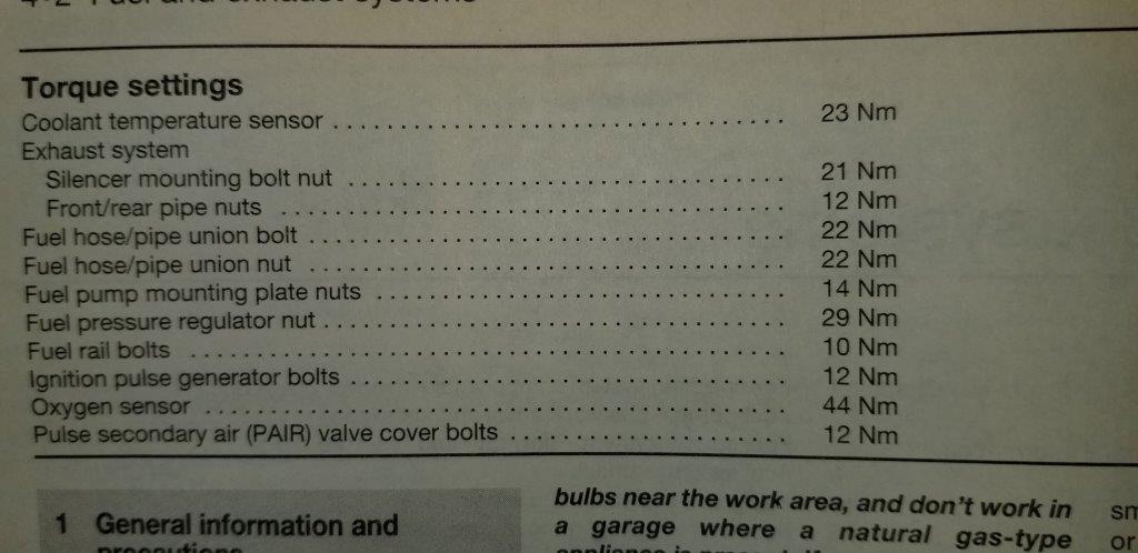
12Nm is less than 10lbs. Very little.
What can happen if you really crank is that the flange will bend, and this will spread the studs. One of my front cylinders had spread studs, obviously a byproduct of the PO's first attempt at installing the Delk headers I yanked off. I had to tap the flange over the studs to get them down, then walk the pipe into the port with the nuts, which is sub-optimal.
If this is the case for you, what I did was go back and forth, a couple of cranks on the ratchet here, a couple there, until the resistance started to increase. Then I gave them 1/4 turn each and was done. I actually think this was too much torque, even, as Lance and I talked about how much 9lbs was and how little it takes to bend a flange.
I got NO leaks. I rode the bike for a quick Italian Overhaul to set a baseline for my rapidbike and checked for leaks. None. I then ran errands letting it heat up and cool down 3 times, then checked for leaks and found none. 12Nm is plenty.
-
2
-
-
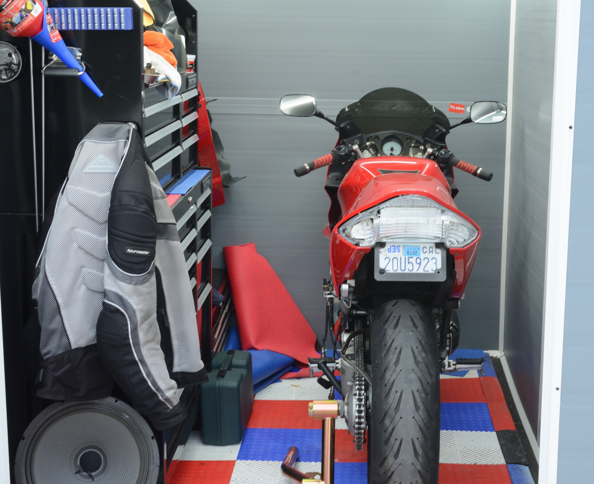
OK, I put it back together. People in the other thread don't seem to think my pictures, which made this process take literally twice as long as had I just done the shit and moved on, illustrate exactly what I said. Or maybe they think I'm stupid. So fuck that shit, I just buttoned it up and I'll show one or two things, but no more expansive pictures of everything.
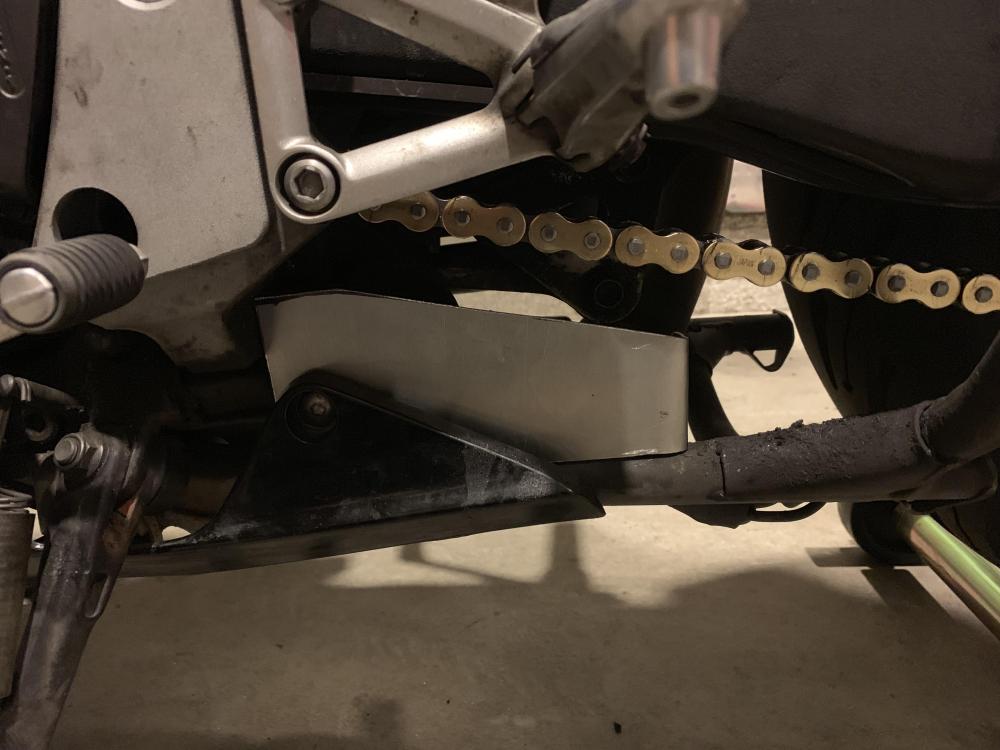
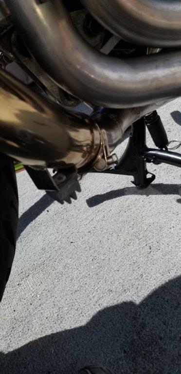
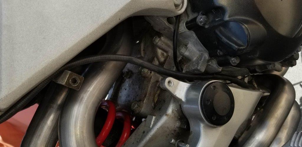
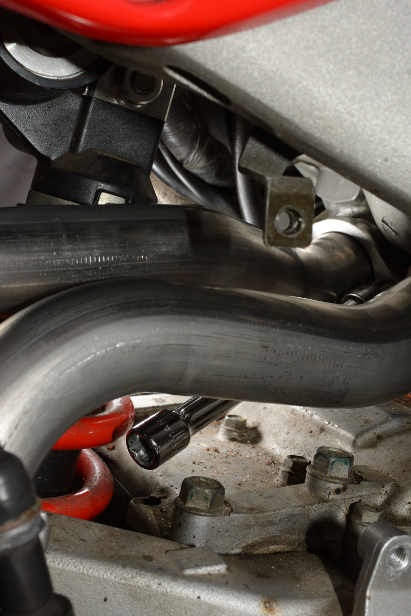
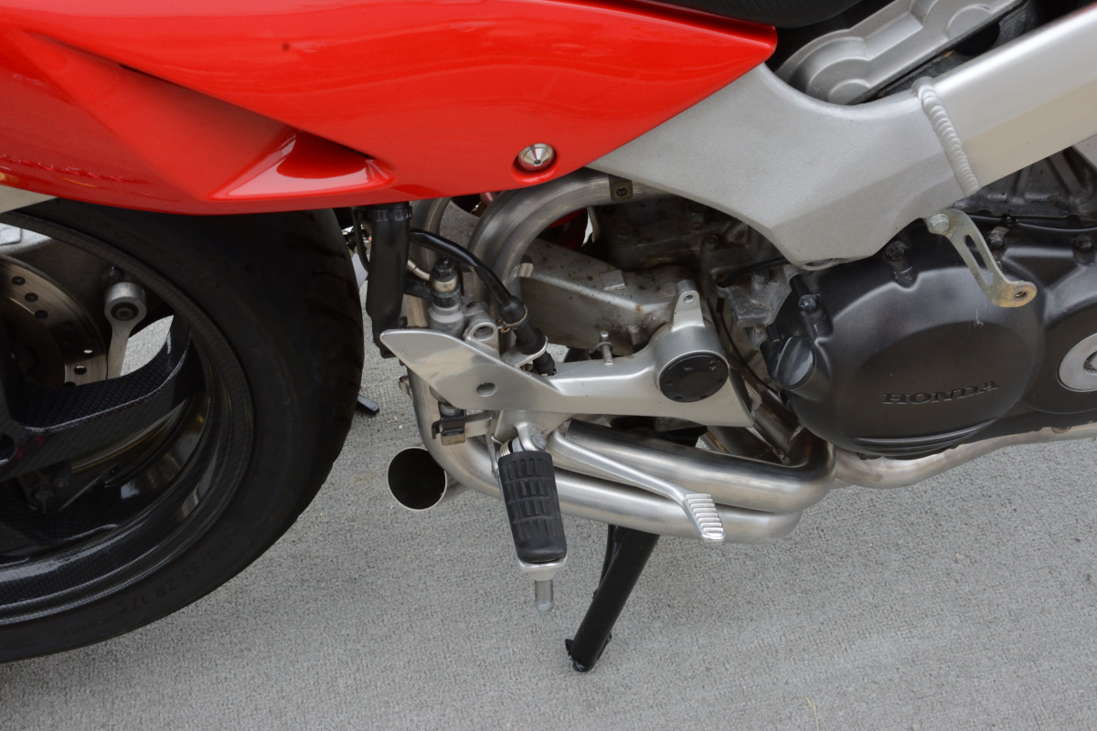
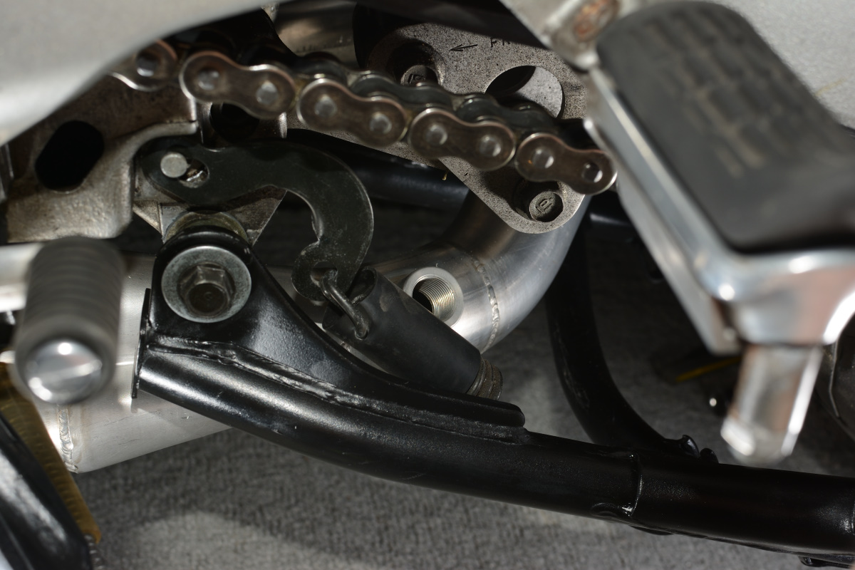
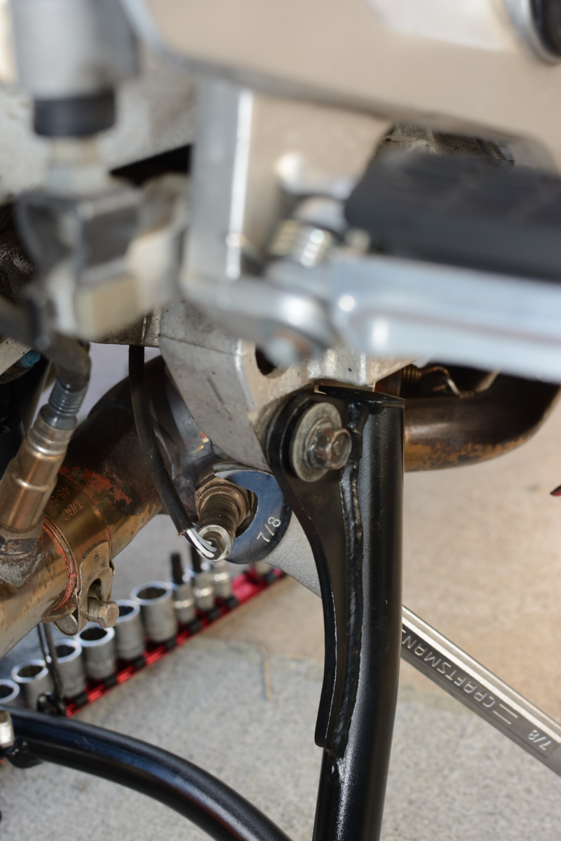
First problem: centerstand spring fouling.
The solution was twofold. First, I flipped the spring. PO had it spring toward the mount, I put it spring toward the crossbar, so the long, thin part was near the sensor. This made it so the sensor fit, but it was still super close:
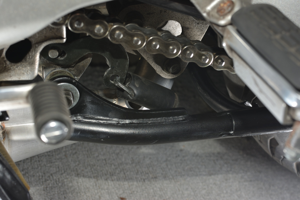
I expanded the connector pipe a bit farther in, so I could position it differently. Then I added a fatter stopper -- the Stock Honda one is a few mm fatter than the one that was on there. These two things bought me about 3mm so the spring clears the sensor with enough room to be safe.
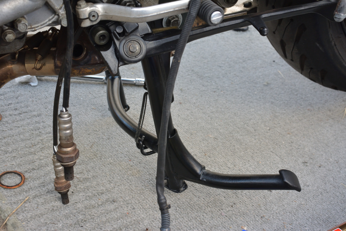
The pipe is close to the tire, but still has enough room to comfortably clear, and lines up adequately. Note the scrape in my fresh paint where I accidentally let the centerstand twang up into the retracted position when I was switching stoppers
The stock Honda stopper is nice and thick
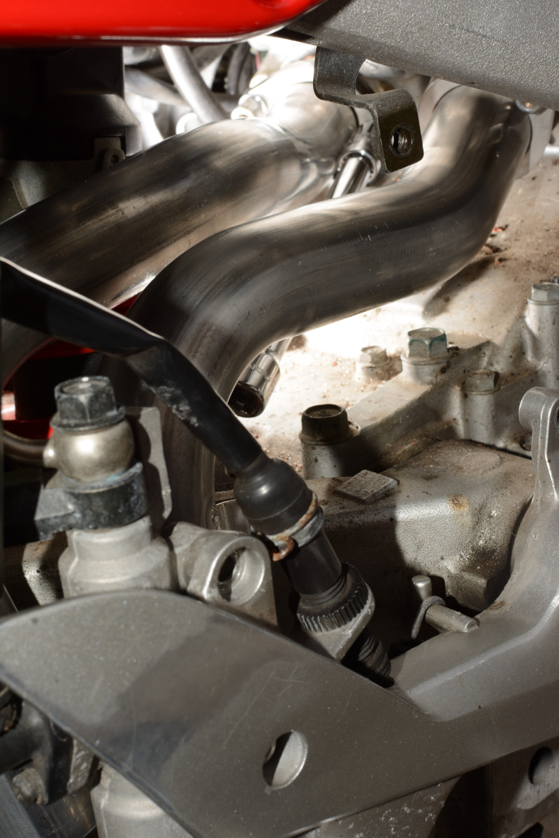
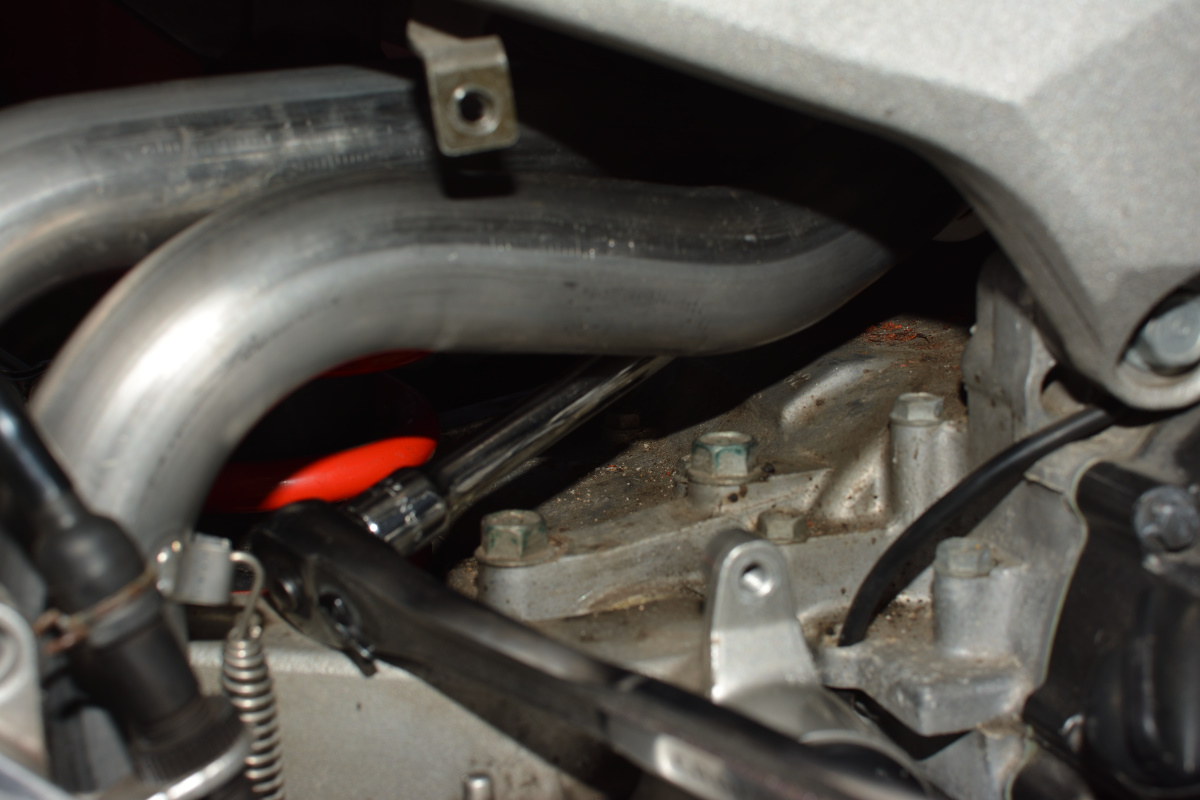
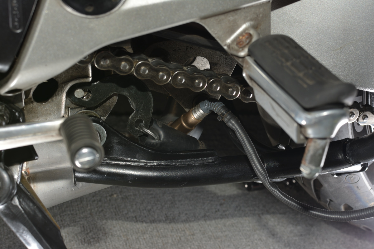
Another note on the 3rd hole sensor. It's really not easily routed -- that sensor points to the chain and the swingarm with no safe place to run the cable up the left side of the bike. My old setup was pointed Right, so I had a lot more options. To keep it from getting loose and rubbing I attached it to the mounting point for the stock headers:
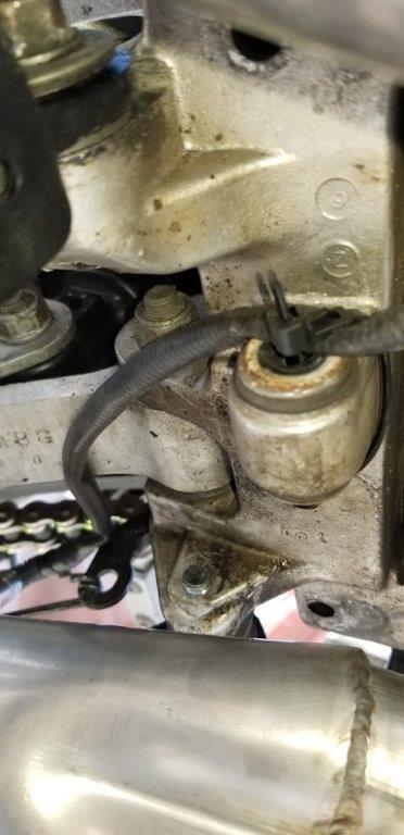
Note: Your headers are no longer attached to the bottom of the case. You probably do not want to use them as a jack point like you could with the stock collector.
After that the sensor run sneaks up between the clutch cover and the peg holder:
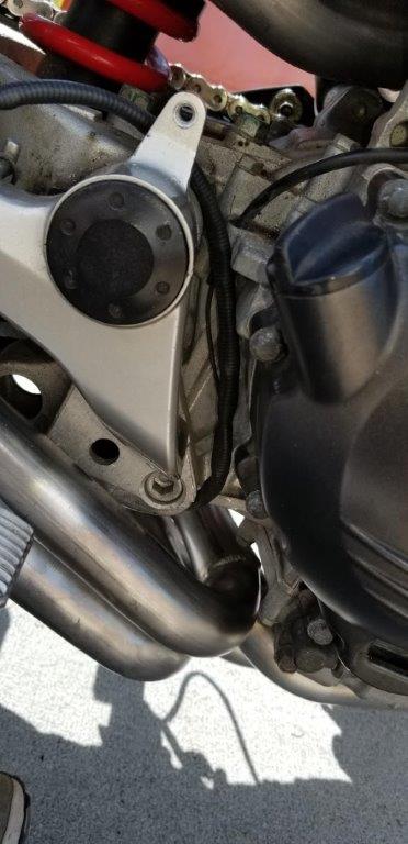
I wanted to make sure it stayed tight so it didn't rest on the pipes.
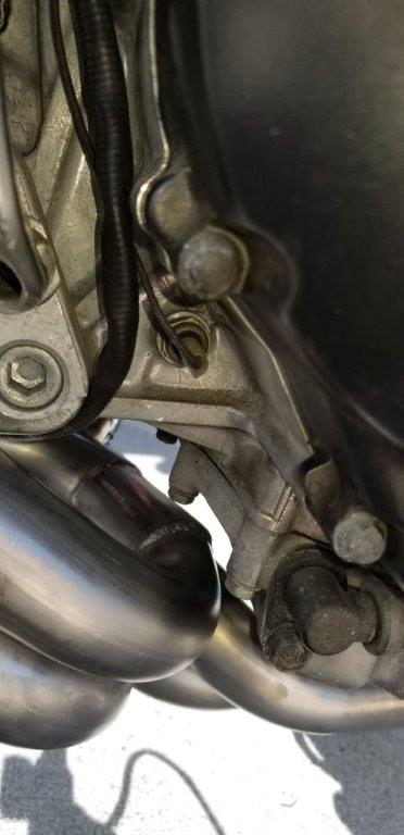
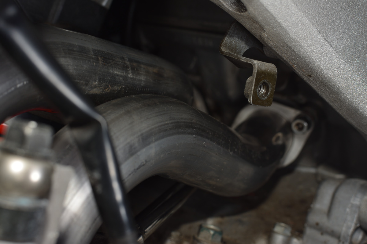
I then routed it behind the heat shield. I zip tied it to that bastard of a mount that is always in the way, so it cannot touch the headers up there and stays secured
From there it comes into the rear subframe and I plugged it into the Rapidbike module behind the brake fluid reservoir. This should be good, every point is hard, so no bouncing around on the swingarm or anything to cause wear.
When I put the plastic on I had several issues. The first was minor. The stock sensor rubs against the plastic just in front of the sidestand:
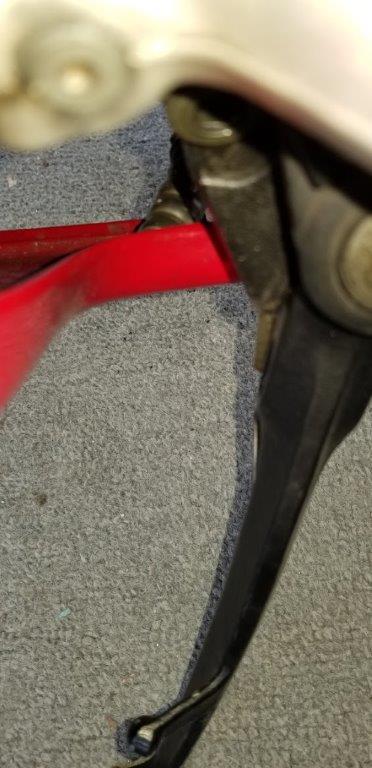
My solution? I don't give a shit. Let it rub. It's not enough to really harm anything.
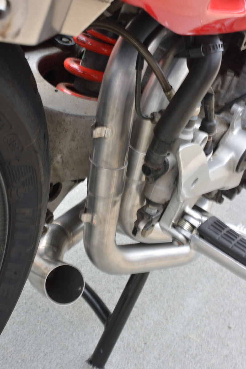
The other minor issue is the right side lower comes kind of close to the pipes. I didn't take a picture of this. I don't think it's an issue, though it's closer than I'd like. I might wrap that pipe. I'll ride it a bit and see how hot the plastic gets.
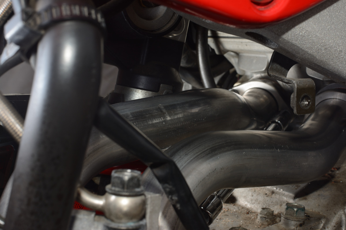
The REAL issue, though, is that the front headers rub against the chin fairing. Not just a little, a lot. The right downpipe made major contact.
My solution there is to just grind away some of the fairing. Hate to do it, but I'm not taking the headers off and there's no other way to make it fit. Oddly, after I thought I made it fit it wasn't enough clearance, so when it got hit it still melted the plastic some. I'll have to do a little more dremel doctoring later. Nobody will notice.
-
4
-
-
2 hours ago, BuzznerSuntrusts said:
6TH GENS! (ONLY?)
Not sure on 8th, but 5th is standard.
Beat me to it. My 5th gen is standard.
Torque these to spec, too. They have lot of threads for medium loctite, and a wavey washer. These do a great job at keeping them from vibrating out. There's nothing to be bought by overstressing the bolt.
-
1
-
-
Gee, I didn't think to try either of those things.
It's not as close as it looks and there's a whole lot of pipe out of frame. There are only so many angles you can get to and I had no leverage to expand anything.
Just plan on dropping the center stand on a 5th gen to feed it through. It's two fucking bolts and you probably should clean and regrease that mount anyway.
-
No time to write now, but I got it together. More tips on fitting issues later.
Here's the first start and checking for leaks:
-
4
-
-

That's a 5th gen. I had to drop the stand.
-
You CANNOT fit that centerstand through the gap between the downpipes and the outlet on a 5th gen. At least on mine you can't. I just tried yesterday. You have to weave the centerstand up through it, which means taking it off, fitting it through, then ataching the centerstand before attaching the pipes.
I took illustrative pictures.
-
You have to drop the headers to get the centerstand on. They basically have to go on together, in fact, lower the headers and thread the stand up between, bolt on the stand, then put the headers back into place, There's just no way to get the bolt in the right side space otherwise.
-
2
-
-
So I got them installed -- ish.
After work I pulled it out and started.
Note the small parts, carefully inventoried and accounted for:
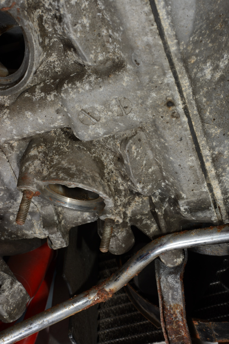
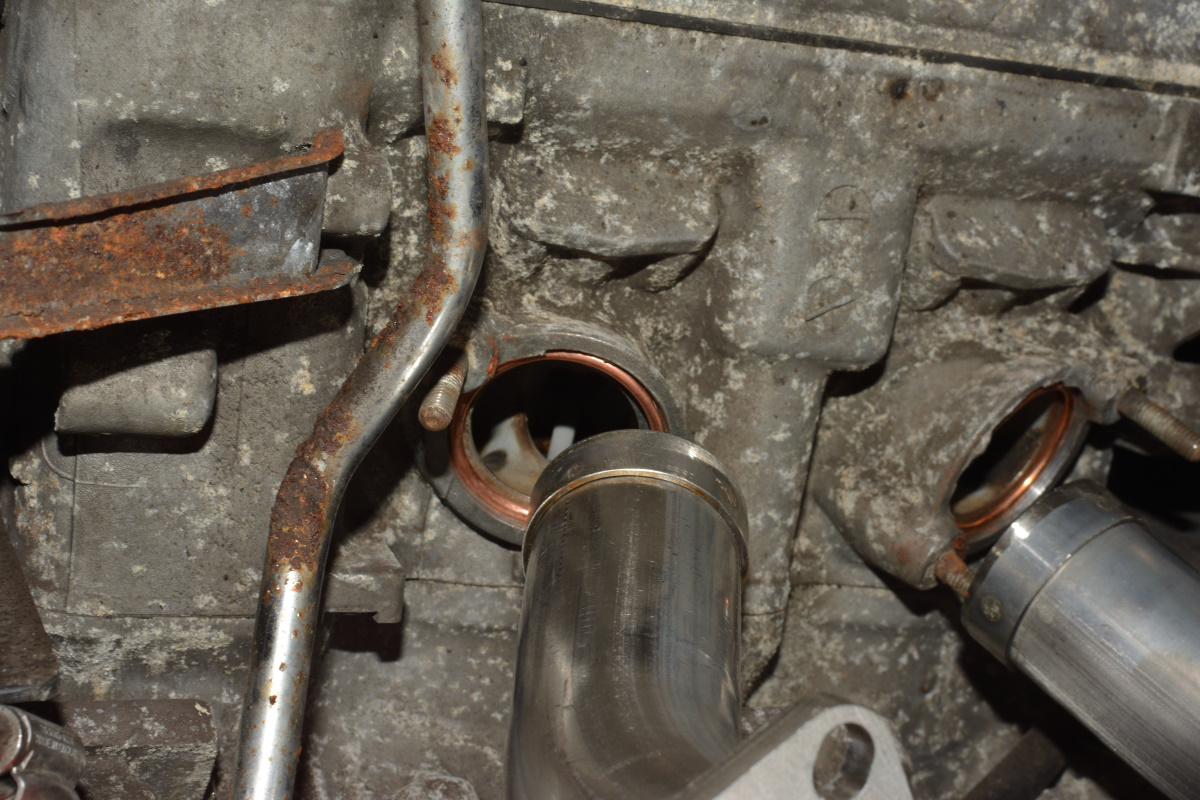
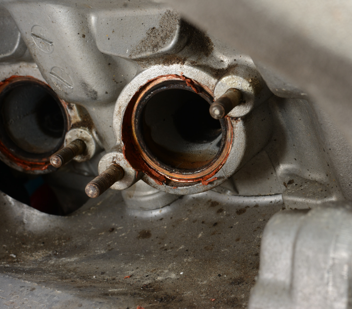
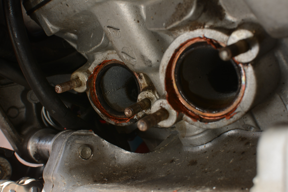
Previous owner was a dolt. I spent a lot of time scraping his permatex out of the ports. Here's a pic mid-cleaning:
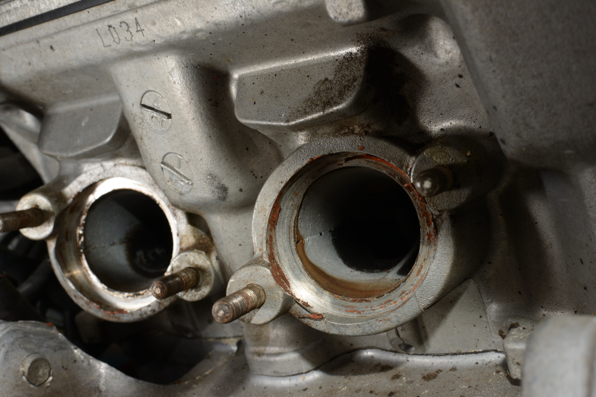
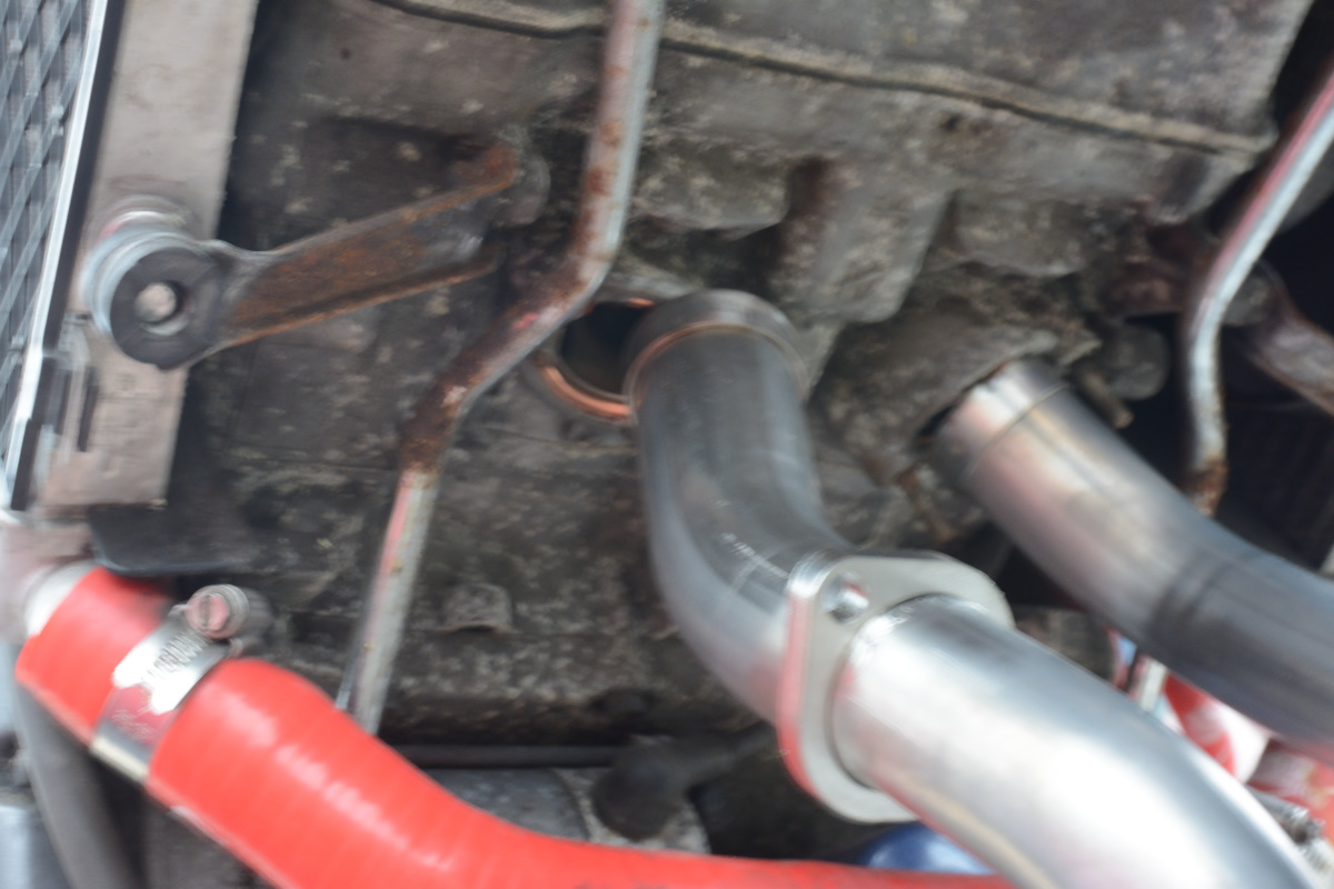
Front ports, too. Here they are almost ready:
Gaskets are a tight fit. That's good, I guess. They'll form around the end of the pipe as it gets tightened and shoves them into the seat. Here they are test fitted.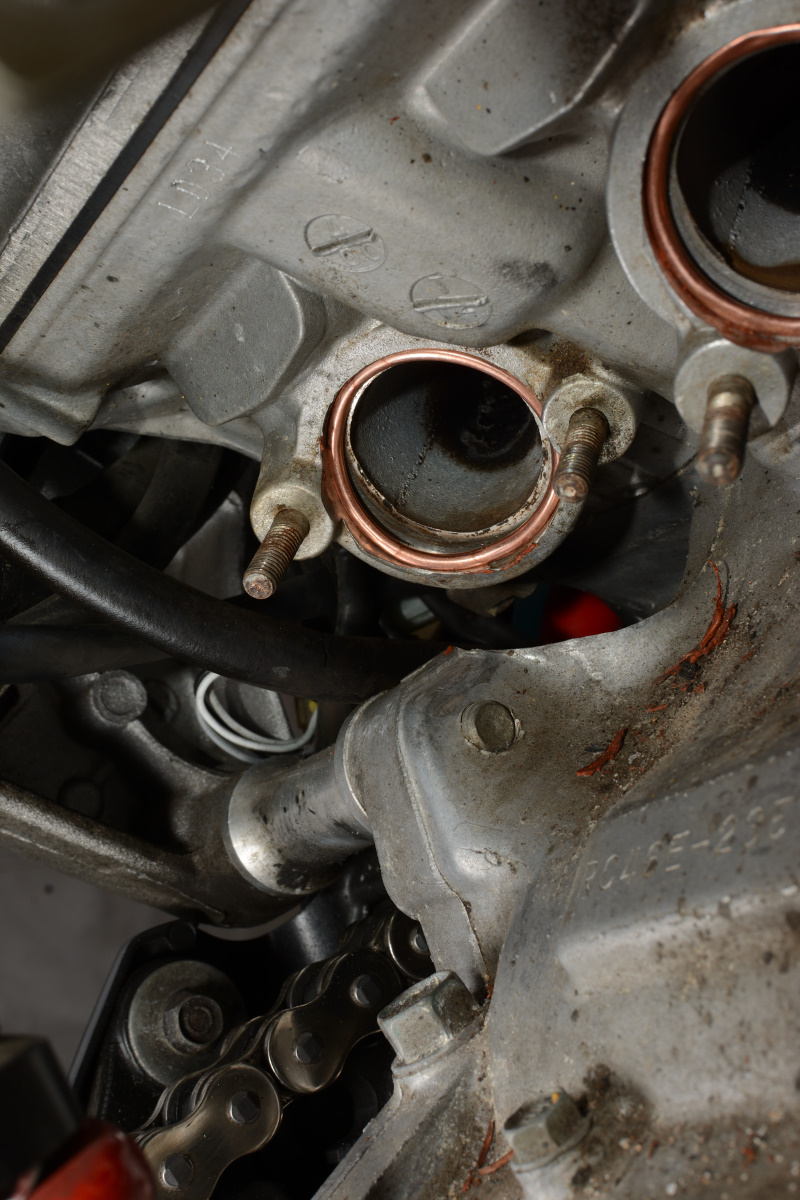
They just stay in place by themselves.
I lined up the rear pipes and loosely held them in place with the nuts. Don't forget antisieze before you put the nuts on, it's annoying to get in there and take them off again.
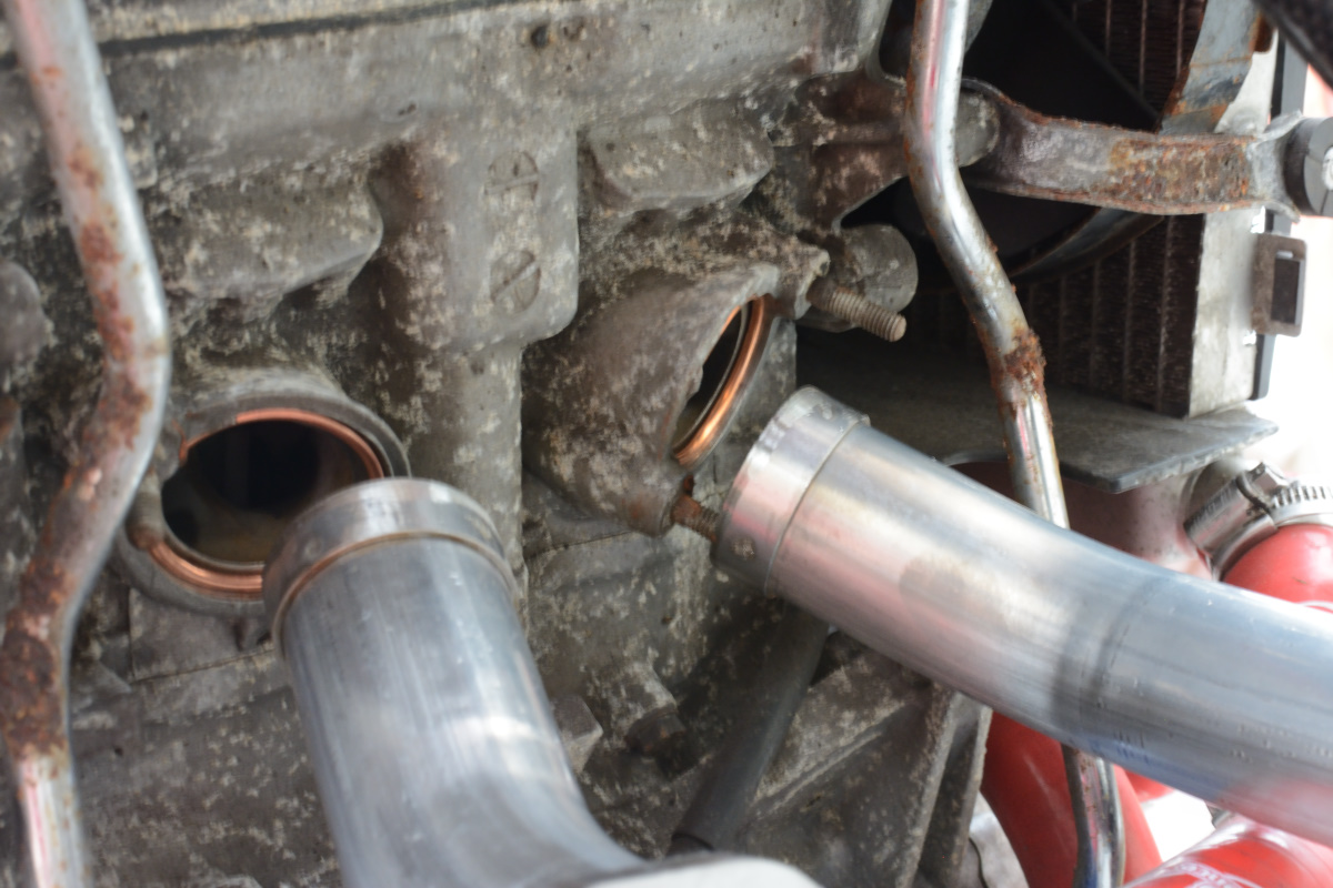
So, if you noticed in the previous pics each port goes out at an odd angle, so it looks like there are cockeyed studs. Not only is that my new band name, it's Honda's engineers being smart about maintenance access. Each one points to a gap in the works where you can get a ratchet, as long as you have the correct length of extension. So this bolt, my long extension and short socket works:
Same for the next stud over, just enough room for the ratchet:
On the left side rear, extensions are too long, but a deep socket is just enough to get the ratchet between the shock and the stud and work properly. You'll find the extension clears the exhaust up front, too, you'll just have to work around the radiator hoses.
If you're having any trouble getting the nuts threaded, take this little bastard off. It's the heat shield mounting bracket. I left it on so I didn't have to detach it from inside, but it was constantly in the way.
So, problem one: There isn't enough room for the pipe to clear the centerstand.
You have to drop the centerstand, feed it into the gap in the pipe there, then re-attach the centerstand before you can wrassle the headers on the front.
SF's advice was to loosly fit the rear pipes at the slip fitting to get things lined up for the front. This is opposite of Honda's advice, they say bolt the fronts on first.
So I got them loosly fit int he loosly bolted rear pipes -- trust me, you'll NEED a lot of play at first, so just thread the nuts on a little bit back there -- then attempted to line shit up up front.
So, I go to lift the fronts up and -- what the fuck man? This isn't even CLOSE to fitting:
For some reason, TBR made their pipes very narrow, and you have to somehow spread them out to get them into the ports. I mean SUPER narrow. Like, line one up with a port and the other one is only covering 1/3 of its port.
I texted @sfdownhill and asked if this was normal. His response was that this was expected and that he found lining up those back pipes first and loosely slip fitting them helped to get these lined up.
I found that a hammer and strong language were more helpful.
Then I did a magic trick to get these lined up with their ports a little better.
Back to the olden days, when I was pre-internet internet famous for "Moose's Wonder Jig", an appropriately sized piece of 2x4 for getting the radiator out of the way when changing plugs on a 3rd gen. I found a wedge of wood and pounded it between the pipes.
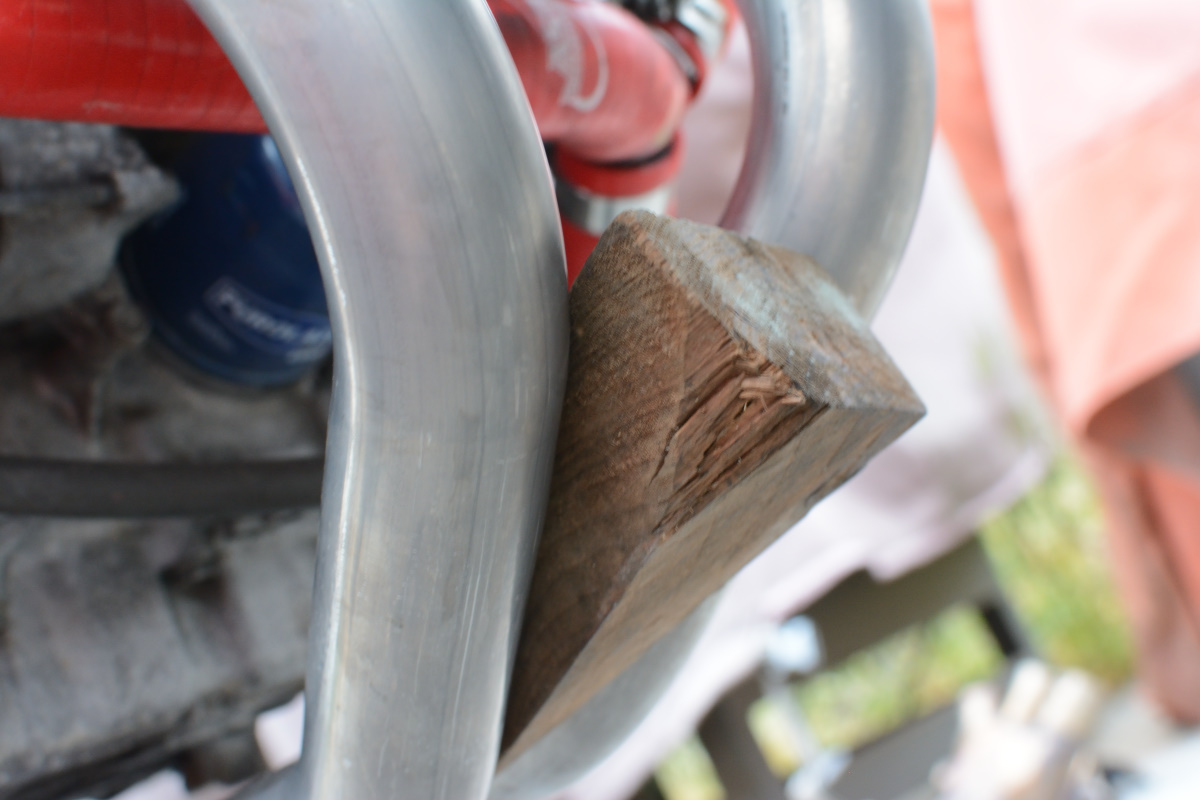
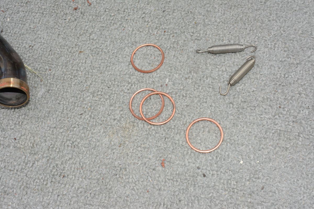
From there it was some wrestling, I got one bracket over the studs jsut enough to get one nut screwed a thread in, tapped the other side (another piece of 2x4 on the outside and some gently hammering) until it lined up and got that on. Then the same for the other pipe. By this time the back had popped out of the slip fittings, but they were close enough. Everything was a few threads on the studs and I was able to line up the slip fittings and gently tap them into place. I got them close to tight, slowly tightened all the nuts on each stud a little one each side to walk the brackets down evenly and push the pipes into the ports, then slipped the springs over. One spring disappeared. I mean completely. Slipped off my spring puller, I heard a twang, then it was gone. Nowhere under the bike, nowhere in the driveway, I think it launched into a different dimension. Luckily that previous system has like a dozen slip joints.
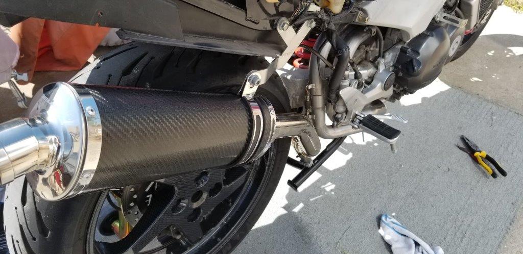
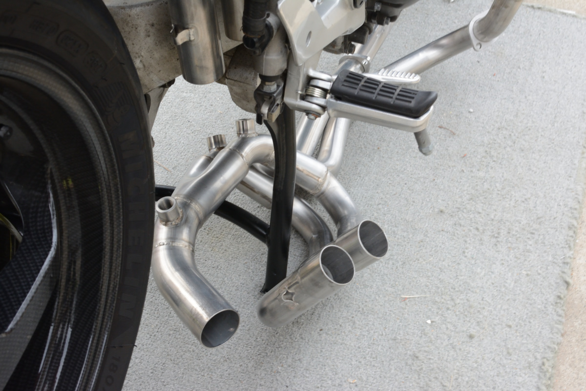
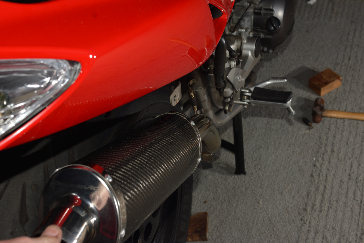
I took this moment to make sure the slipon lines up:
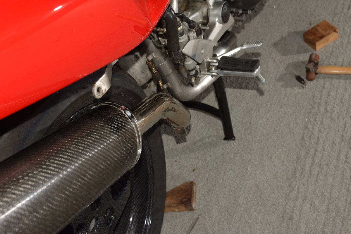
Note the fugly spring. I had to reuse an old one from the delkevic set. Also note couple of Moose's Wonder Jigs lying there and one of two hammering tools I needed to use. There's a deadblow mallet around somewhere, too.
Thankfully the can lines up pretty nicely.
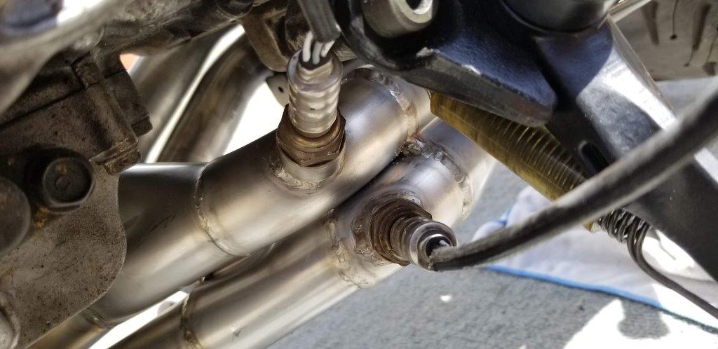
Then I ran into problems. Sensors, sensors, sensors.
First, does anyone know which sensor has the black connector and which has the white? One is 1-2 and the other is 3-4. I've had them disconnected for a while now and I don't know which of that charlie foxtrot collector can from Delk was for which cylinders. Or even if the previous owner had them right.
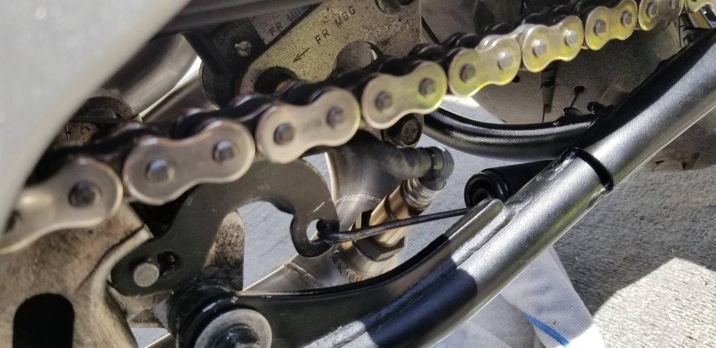
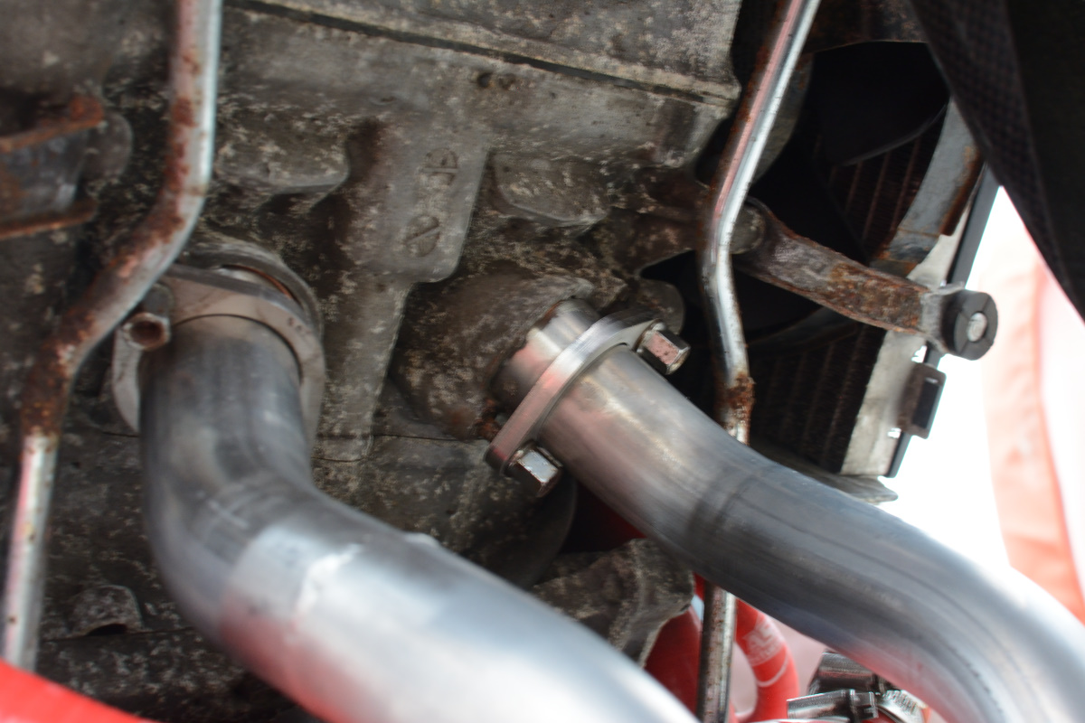
And, second, it looks like the centerstand fouls the Bosch lambda sensor in the back bung:
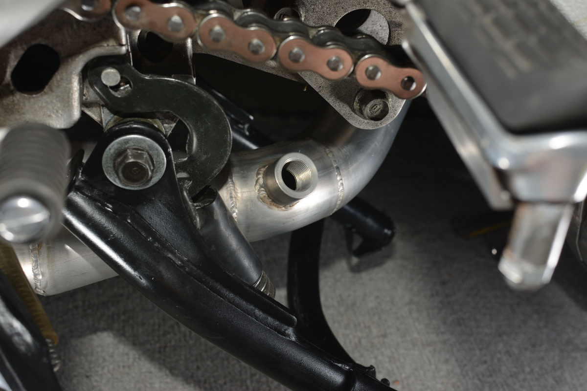
SF claims that he has installed several times with centerstands, so maybe I'm missing something here, but it was getting dark and I'm a driveway mechanic. Had to put my tools away. I'll look at it in the morning and see what's what. Maybe I did something wrong or am seeing it wrong in the darlking light. It'll be clearer in daytime.
So, a lot of effort. The end wasn't particularly satisfying. Just like the debut album from the Cockeyed Studs. Hopefully I'll get those sensors installed and make it run at some point this weekend.
-
3
-
-
Note: This is for a 5th gen. Everything here is MY observation, on my bike, and I have not elided those bits where things didn't go smoothly simply to try and be helpful. Your experience may be different. Your bike may be different. Your headers may be somehow different. Deal with it yourself.
OK, I got started on my installation after work today. So far I have removed the old (Delkovic) headers and gotten some things cleaned up. I ran out of light, so I'll put them together after work tomorrow or Saturday morning.
Additionally, since you have to pull the exhaust to add or remove the centerstand, I started by pulling the stands off and repainting them. the Delk exhaust has a gazillion slip joints, so I was able to just grab the section behind the heat shield and get them out enough to get the stand off, but the new headers are one piece. If I want to add or remove in the future I have to remove the whole exhaust, so now was the time. This happened earlier this week (There's a thread elsewhere with pics).
Steps I followed for disassembly:
-
Strip the lower fairings off the bike.
- Both sides.
- Chin fairing.
-
Remove the slipon and connector pipe.
-
Check the fit of the connector pipe before continuing.
- My connector doesn't fit over the TBR size exit, so I had a local shop stretch it to fit.
-
Check the fit of the connector pipe before continuing.
- Remove the chainguard.
- Remove the heat shield from behind the right foot peg holder.
- Remove all sensors (two if stock 00 or 01, mine has a third for my Rapidbike).
- Remove the nuts from the studs on the rear cylinders.
- With the collector still attached to the mounting bolt underneath, remove the front nuts from the mounting studs.
-
Remove the mounting bolt holding the collector can.
- Delks come apart in pieces, so that was a matter of popping them apart.
- Stock (and the new) headers will come apart at the rear downpipes, but the front will come off as one large unit. You'll learn to wrassle it around when you see it.
- Remove the old crush gaskets from the exhaust ports.
- Clean up and get ready to put it back together.
I'll have pictures below of a few things I found on disassembly.
Steps I will follow to assemble (Note, they aren't the same as in the service manual):
- Attach the centerstand.
-
Insert the 42mm round crush washers in the rear ports.
- Use Delkovic round 42mm washers.
- These are the only ones to use! They are proven to work, anything else is likely to give bad results.
-
Loosly attach the rear downpipes.
- Use high temp Antisieze on the studs before you put the nuts on.
-
Do NOT Torque the nuts!
- At this stage you want the ends holding the crush washers in, but the pipes should have a little wiggle room.
- Insert the crush washers in the front ports.
- Put antisieze on the front studs.
-
Wrestle the larger headers into place.
- Line up the ends with the slip joints and put them together loosely.
- Get the front downpipes lined up with the ports.
- Put nuts over studs finger tight on the front.
- Make sure the rear slip fittings are tight, then put springs on.
-
Torque the nuts down
- Go slowly -- this pushes the crush washer into its seat
- Toque is NOT much -- 9ft/lbs or 12Nm according to the manual
-
Reinstall the sensors.
-
These don't seem to have consistent torque specs... I've seen everywhere from 15-30 lbs.
- hand tight and a quarter turn like an oil drain plug is conventional wisdom.
- They have a crush washer and threads, they're not going to leak with reasonable, 20lbs torque.
- You can't fit a socket over them anyway, so it's all just a well calibrated elbow and a wrench.
- Use antisieze.
-
These don't seem to have consistent torque specs... I've seen everywhere from 15-30 lbs.
-
Give a brief prayer to your deity of choice that the connector pipe will line up adequately, and fit the connector and slipon.
- Get a snug fit.
- Line up the can in the clamp/holder behind the rear pegs.
- Tighten the clamp over the connector at the headers.
- Tighten the bolt holding the canister.
So far, I got the old stuff off. I didn't install the Delkovic system, the previous owner did. He told me he had problems with leaks and he wasn't a great mechanic. Handy with tools, but overtorqued everything and didn't understand anything beyond the step by step instructions, so I have redone a lot of really bad work he did. However, he didn't overtorque the exhaust nuts!
That said, he used incorrect washers and held them in place with high temp gasket maker goop. Everything is coated in the copper Permatex. Heh. Anyway, I have it all off now.
First, I got the the slipon and connector off, then I got to work on the sensors:
I want to note that this is the ONLY time I ever use that wrench for actual wrenching. Though I use it a lot. It's the perfect lever for popping the left side of the throttlebody out of the boots, and I've done that more than a few times. But now I get to use it as designed!
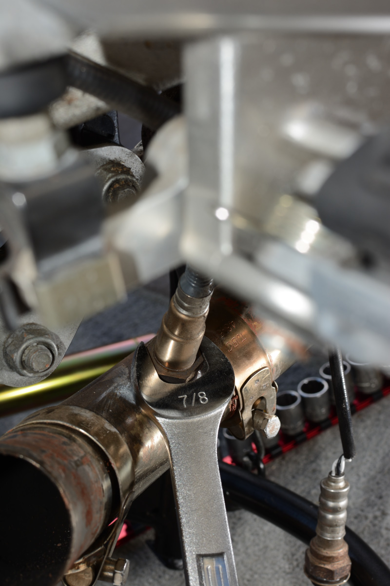
So, now the muffler is off and the sensors are out. I suggest you start the bike at this point and rev your engine for at least 10 minutes. This will both make sure all the exhaust is blazing hot AND will assert your authority over all your neighbors. Chicks dig a man who can handle 500 degree metal, and love confidence. The glorious, unmuffled noise will let lesser men know that you are dominant. The equivalent of being the baboon with the biggest, reddest ass. There's no downside here.
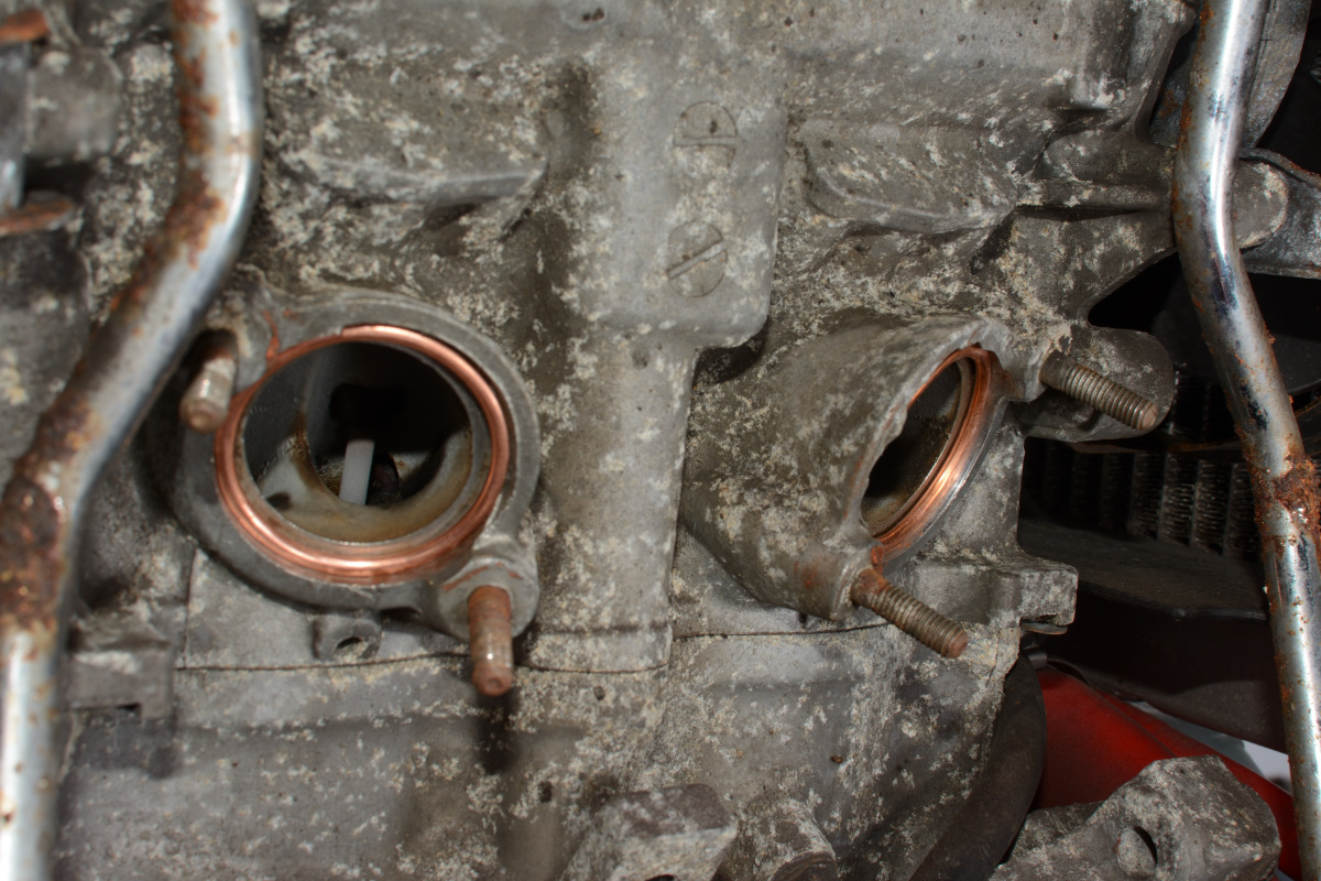
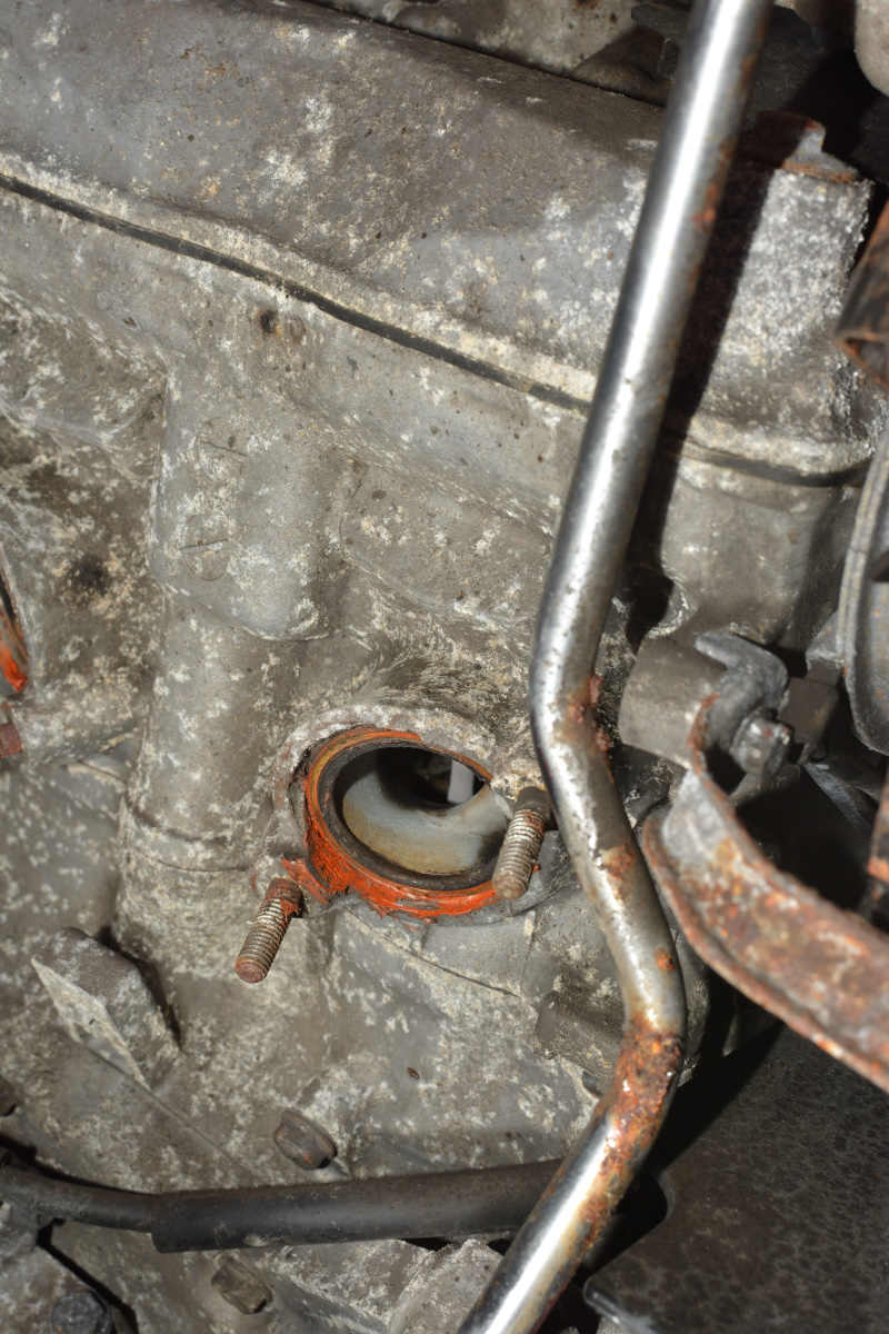
Next, I took the back downpipes off and got a look at the ports:
Yes, he did hold the crush washers in place with copper permatex. He's a nice man. Enough said.
I was worried the washers would be frozen in place, but he used too small a washer so there was a lip I could hook and pop them out:
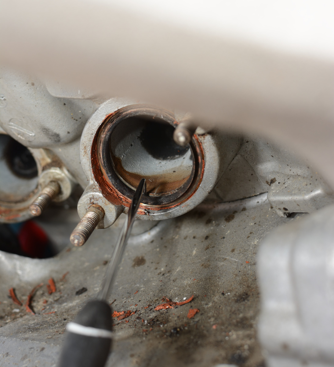
More about that lip later.
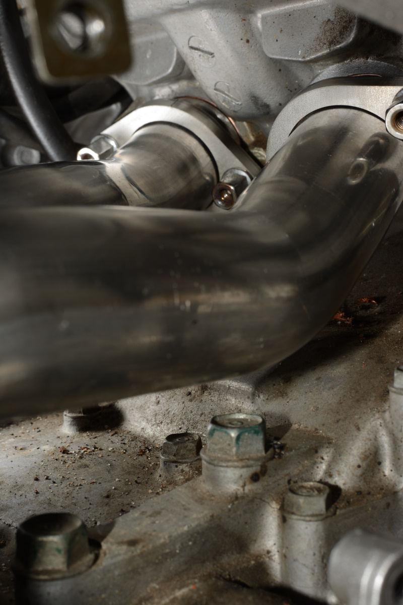
I pulled the front off and was also greeted with not overtorqued nuts. Thankfully. I was able to just pop the downpipes out of the slip connectors (you won't be able to do this for stock or the new system) and got a look at the front ports:
The front of the engine is really grungy.
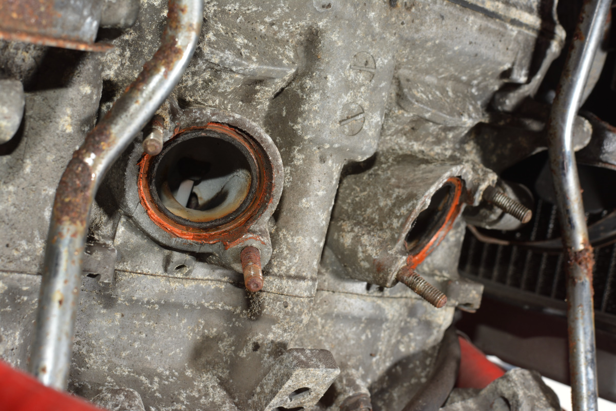
Lots of permatex:
Again, I was able to pop these washers out because they had a goodly lip on them.
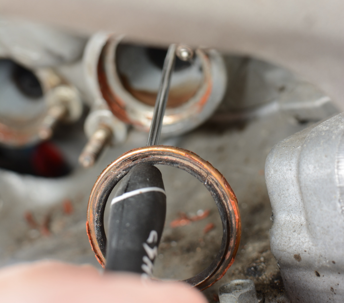
And here's why we use the 42mm Delkevic washers that SFDownhill has proven work properly. Take a good look at the black part of this crush washer:
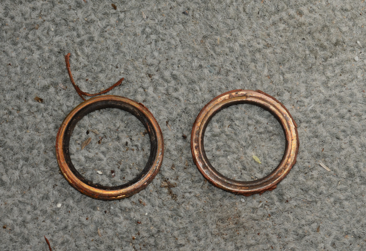
That's all INSIDE of the inner diameter of the Delk downpipe. That pipe is osensibly 34mm id, but this crushed out washer is a couple mm less id. The black parts actually stick in to the port a bit, so there's about a mm lip I could feel, and was able to hook to easily pull this washer out. On the one on the right you can see it formed INSIDE the header, but not outside. Lance's photos show the crush ring smooshed into the corners of the ports, wrapped around the pipe, and not restricting the pipe or the port itself.
It's amazing what a difference a couple of mm here and there can make.
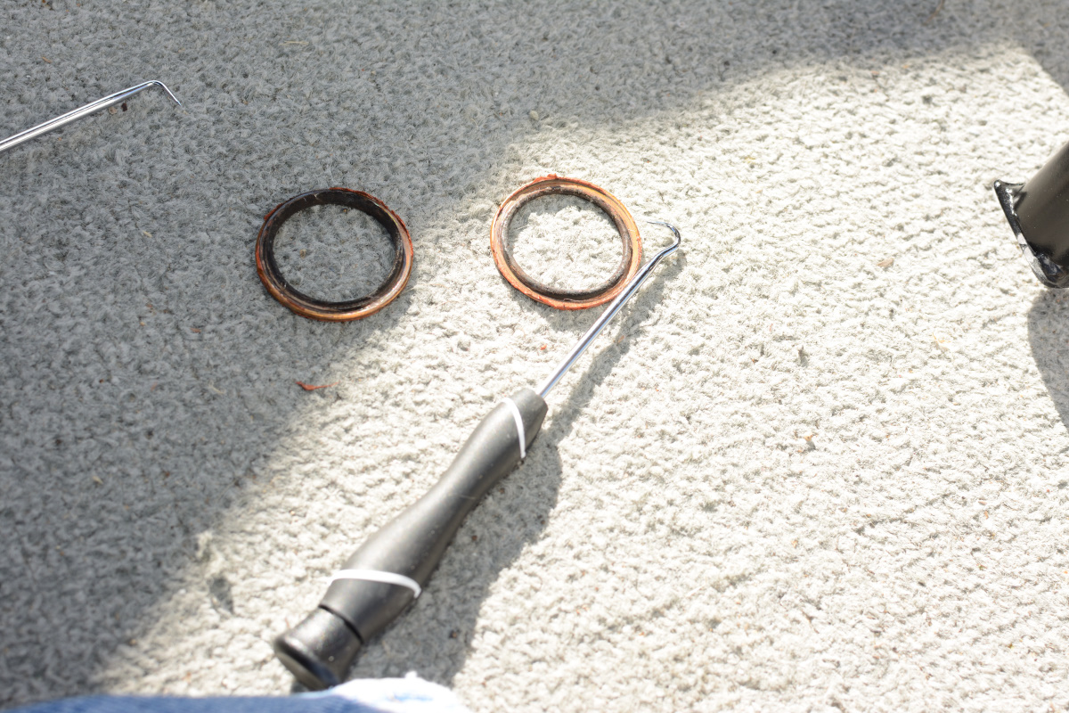
So here's some comparison pics before I put the new pipes on. The port ends are actually pretty close to the new ones. The Delks are 1mm less inside and outside diameter:
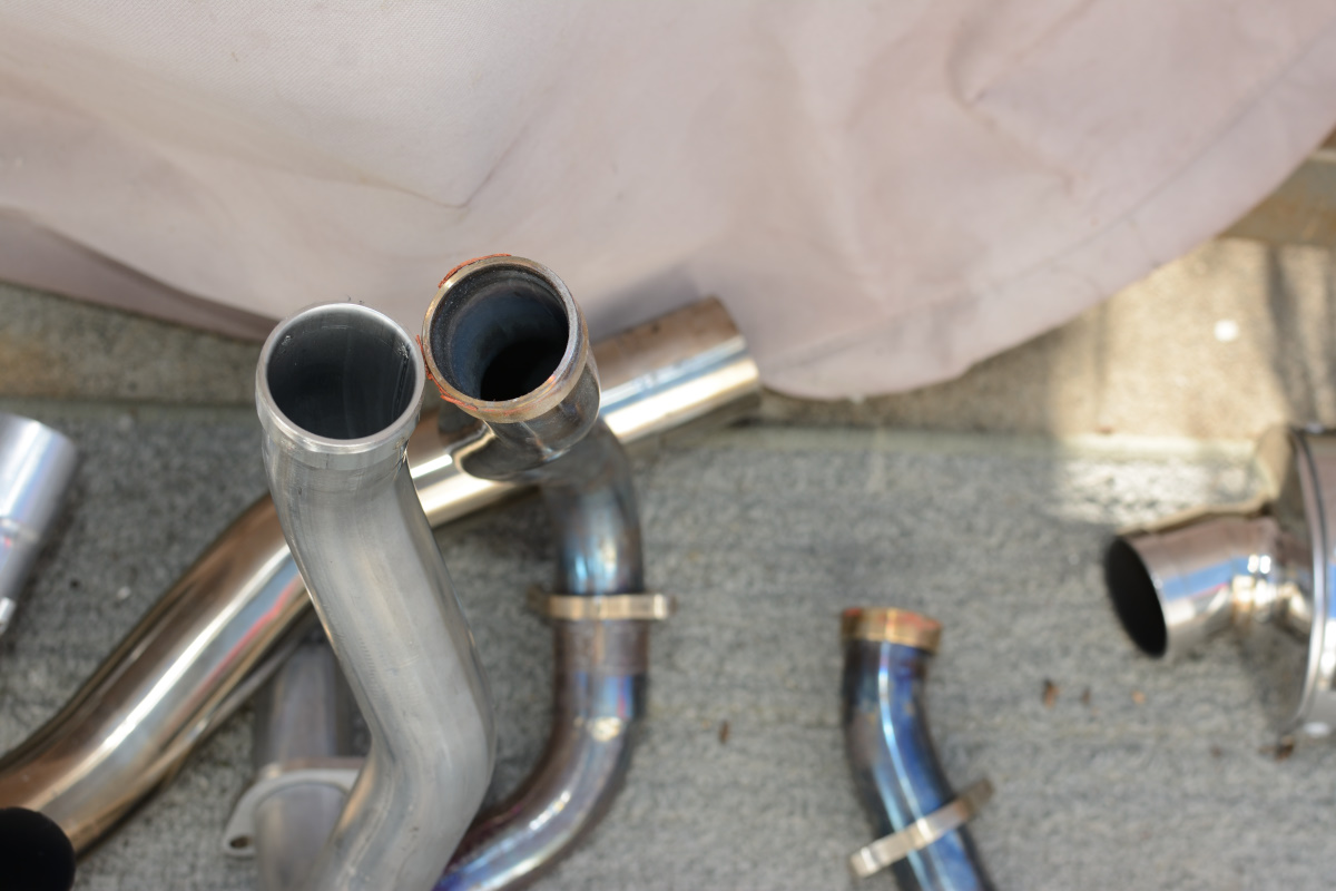
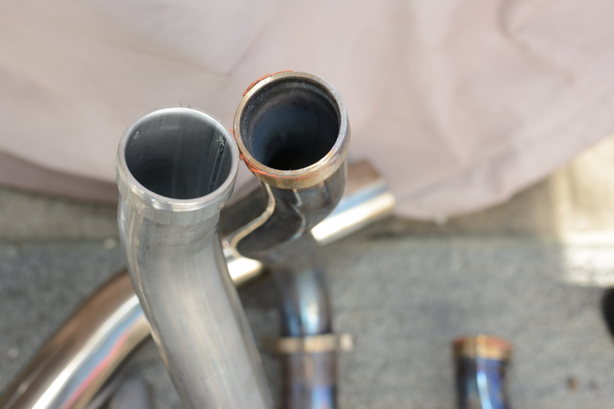
The new ones are beeflier farther down, though:
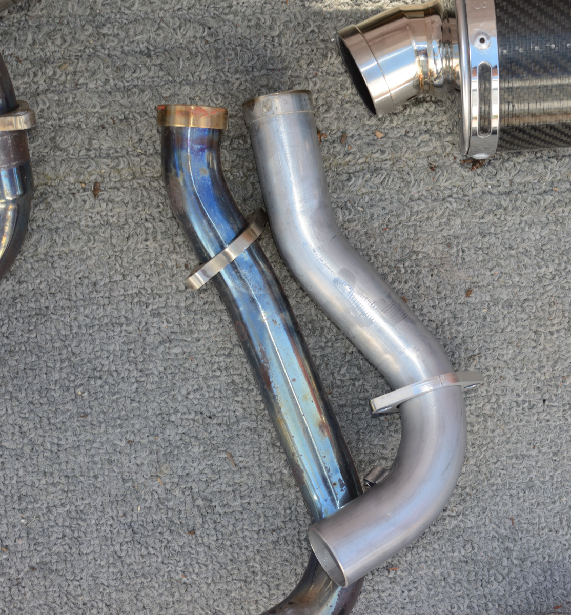
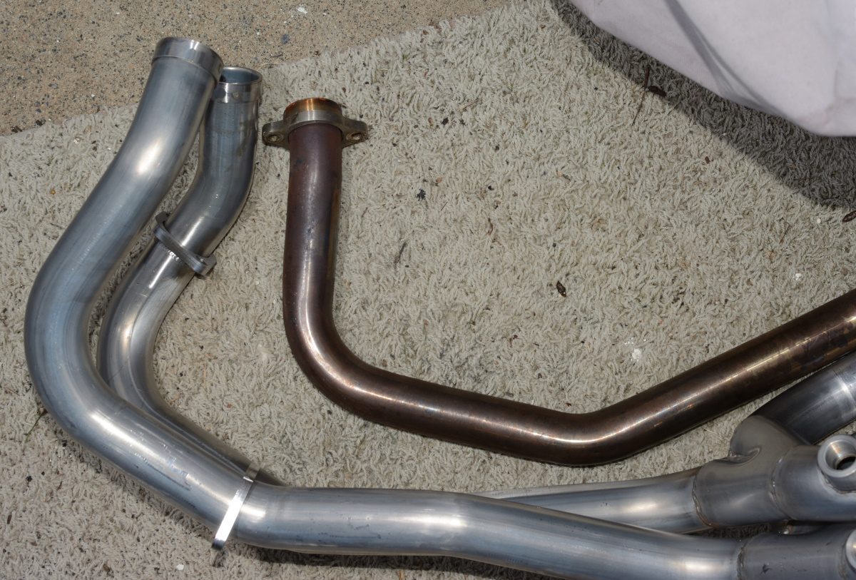
here's the fugly merge on the Delks:
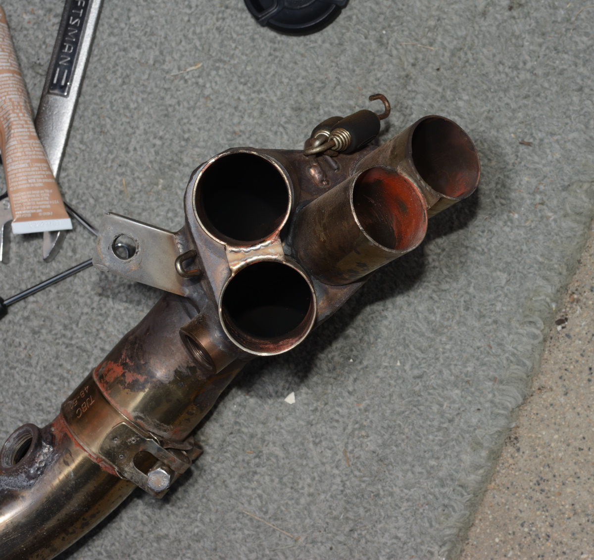
I'm sure between the gaskets sticking into the ports and this clusterfuck of a collector I was giving away a couple of horsepower, just from workmanship.
I cleaned that permatex crap out of the ports and was out of light, so I put the bike in its shed for the night.
More coming in a later post when it all comes together.
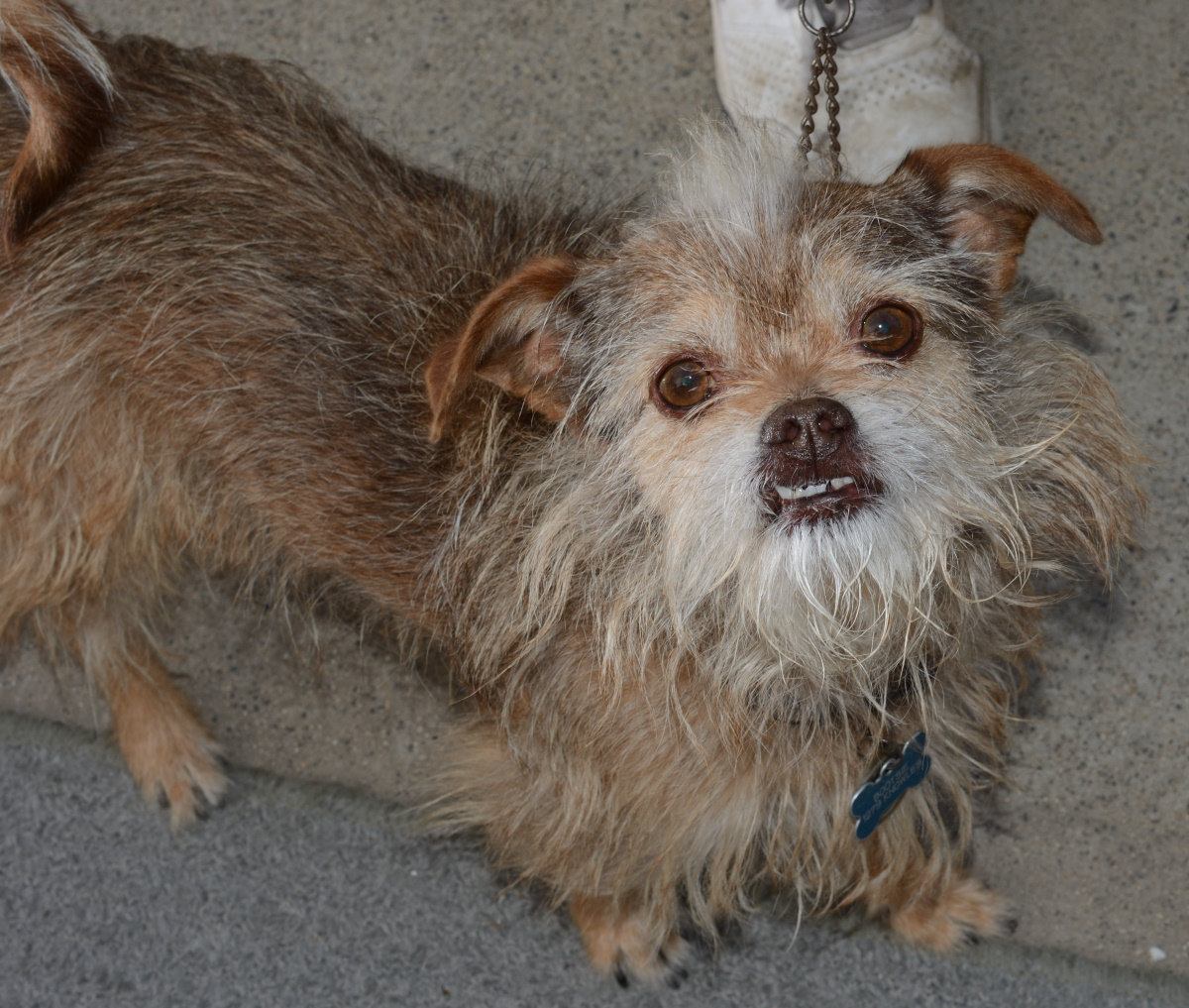
Here's the roommate's dog who was taking his afternoon constitutional while was photographing exhaust gaskets. He's ugly on the inside, too.
-
3
-
Strip the lower fairings off the bike.
-
Yeah, it's bland, Dash. That side stand is ever so slightly blacker than stock, but close enough to stock you can't tell.
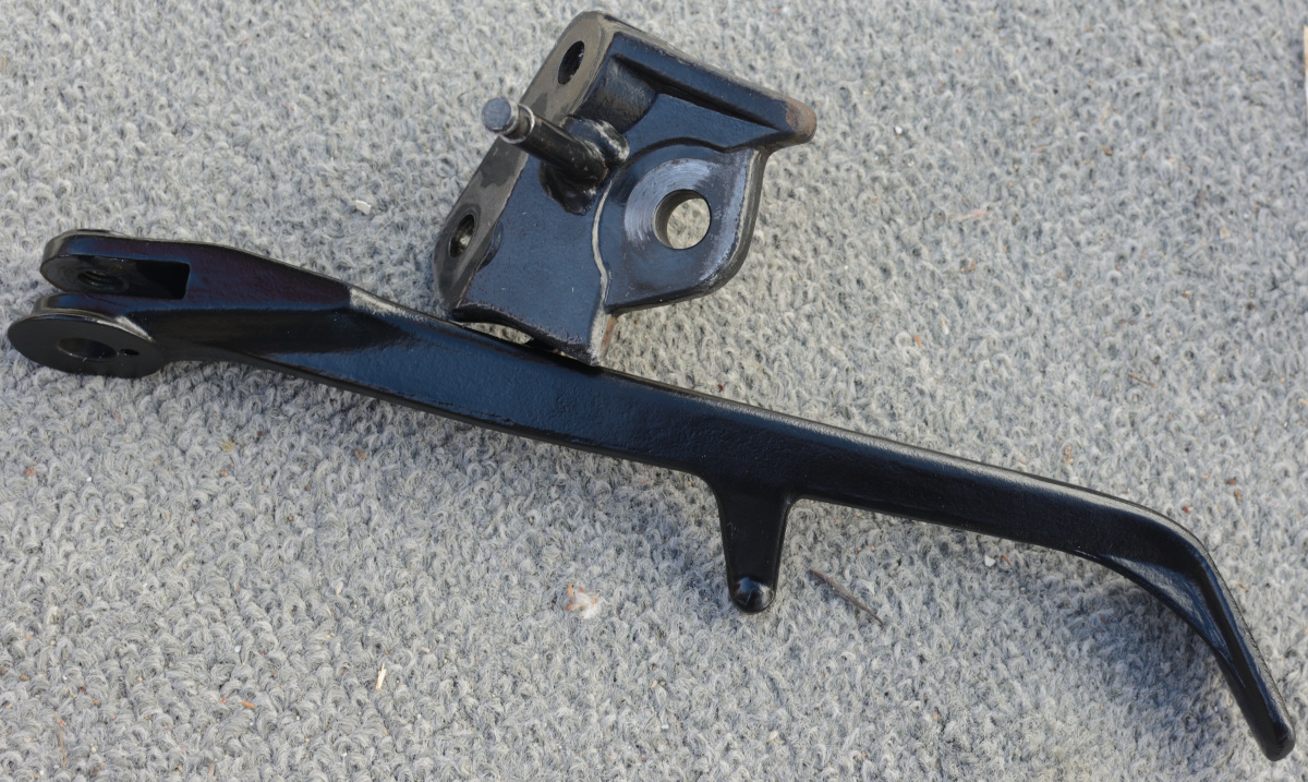
The mounting bracket is still stock paint.
The center stand I did a bit of polish on and got that paint to look good. Smooth. But just a tiny spot because, screw that noise I'm not wasting any more time. I think Honda just powder coat it all the same color as the subframe, as though it isn't going to be seen. And, in their defense, it is seldom seen or noticed, and is guaranteed to get screwed up in short order.
-
I think it's Victory Red now. Ever so slightly darker. You can only really tell when they're side by side in the sunlight.
I have a friend that claims Yellow is the fastest color, even on a Ferrari. His logic is "You see a yellow light, what do you do? You speed up!" I have no argument to refute that.
-
 3
3
-
-
23 minutes ago, MaxSwell said:
Such a beautiful machine. And in the fastest color.
Second fastest.
Italian Red is faster.
-
1
-

Installing the new performance header on 5th gen
in Exhaust Systems
Posted
Just for giggles I did run it with RBo2 unchecked.
Oddly, it cruised a little better. It wouldn't switch back and forth between modes as quickly, causing surges. But it would go DEEP into the cruise mode and stay there. Throttle would be really pathetic at 5-10% between 4 and 6K. It corrected, but just seemed to do the corrections more slowly. The map it made was hilarious. 1s, 2s, 3s, maybe occasional 4s one way or the other in most cells at higher RPM and throttle settins, and 11 (the max) in the half dozen cells surrounding 5000 at less than 30% throttle. No wonder it falls on its face!
Whatever, it's a bust either way. Rapidbike doesn't solve this problem. Next time I pull the fairing I'll disconnect the sensors.
Just conjecture, knowing how software works and guessing at Honda's tricks, I don't have actual data, but I think it got into a race condition where both the bike and the rapidbike were chasing each other until the correction maxed out. In fact, it would be fun to do some datalogging to see what's really going on, but I don't have a bluebike module and it's just curiosity for me, not anything that really matters. The fact is that this isn't working for me so I'm going to jam the resistors back in and let Rapidbike lean it off from the map Honda uses when it isn't getting sensor data. It's good enough for a power commander, it's good enough for me.
I should actually buy some bung plugs and just take them out, in fact. Save some fugly wiring routing up behind the coolant tank.