YosemiteVFR
-
Posts
51 -
Joined
-
Last visited
-
Days Won
1
Recent Profile Visitors
2,721 profile views


YosemiteVFR's Achievements
")


-
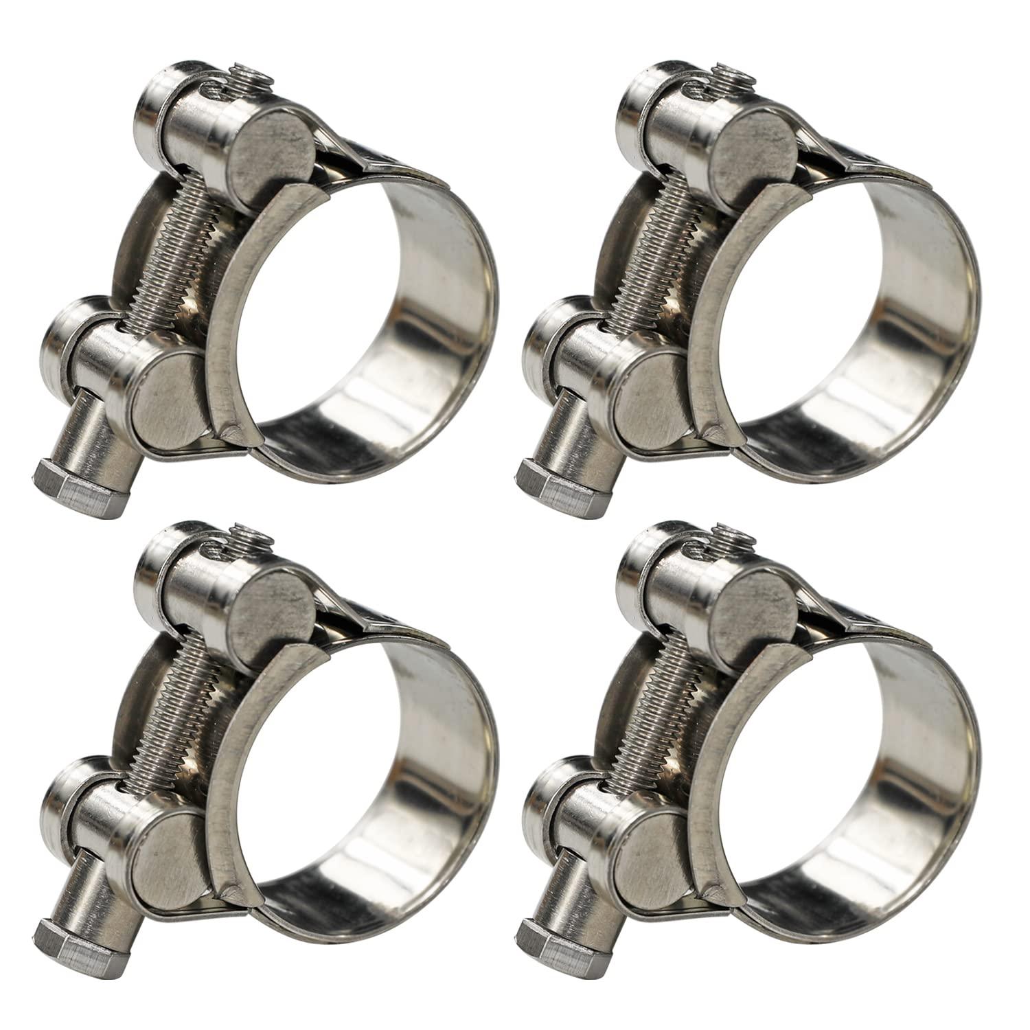
 Thanks for taking the time to provide that info. Since my posting on this, I was able to use bulk 1" hose to connect from the radiator to the sensor I referred to above. Then connect a sourced 25mm silicone 90 degree elbow from the sensor to the T-stat housing. Using t-bolt hose clamps, my first attempt I found the size range I chose wasn't providing enough clamping force before the ends of the clamp interfered with each other. Next size down looks to have worked a treat (29-31mm ID)
-
Another pleased Pit Bull stand owner. Very robust.
-
I can confirm that the Akrapovic option for the 8th gen mounts up perfectly fine on a 5th gen. I imagine you saw a post here wherein someone took the plunge and purchased a two bros low mount and discovered it mounted just fine on a 5th gen. As for the stock pipe’s sound, I actually find it quite welcomed after running a two bros aluminum C-series for a time, so I’ll go back and forth. I guess I’m getting older. 😁
-
There's a segment towards the end of this video on bleeding the clutch master cylinder that I found helpful after rebuilding mine. Motorcycle MD Clutch Slave Cylinder Rebuild Maybe it'll help out.
-
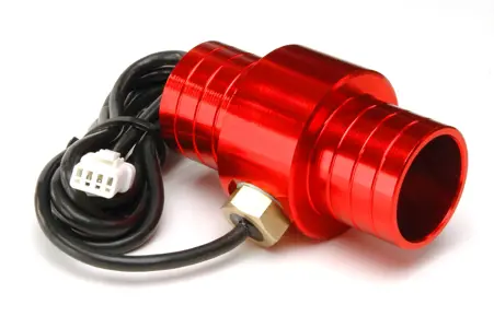
I'm looking at adding a inline coolant temp sensor from Trail Tech until I can get my ongoing LCD in-op issue sorted. I've got two options on the sensor housing; 22mm & 25mm. I'm leaning towards 25mm. I haven't torn into the bike yet and thought I'd ask in case someone had a spare hose or bike apart. On the subject of that discontinued hose; has anyone had success in using (and bending) bulk coolant hose for that application? Trail Tech Temp Sensors
-
I can’t remember if there’s a diagram in the FSM but I’d “top-off” by filling the radiator. Put a paper towel in place to catch any coolant that’s displaced by the cap. Check the level in your overflow reservoir (left side) and make sure the level is between “min” “max marks when cold.
-
Where are you sourcing your injector O-rings, seals, cushions, etc? OEM on these is crazy expensive in my opinion.
-
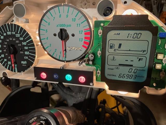
LCD Display went out. Need a little assistance.
YosemiteVFR replied to YosemiteVFR's topic in Electrical
Yes, most definitely a typo - that should have been "11.5v on I+G". Interesting tidbit; the clock will start to function again not long after connecting the bike to the battery tender but will go out after key-on, during the fuel pump prime. I'll pick up a magnifying glass or loop and see if I can see anything the next time I get the board out. Also a routine search of a good used unit. Any progress, I'll share in updates. Thanks Grum, you've given me a lot of good info here. I'm grateful for your time and input! -
I just did this on my 2000 VFR after noticing a leak on one of the seals. Since I wouldn't have the time to disassemble and inspect the bushings first, I just ordered them as well as seals, fork cap o-rings & bolt washers. After looking at the bushings and seeing the condition I could have probably reused them but I felt like it could be false economy considering the bike had 65k miles at the time and so I wanted to start fresh. After setting the oil height and reassembly, I was very pleased with the results.
-
LCD Display went out. Need a little assistance.
YosemiteVFR replied to YosemiteVFR's topic in Electrical
As I recall, in the event the screen is non-op while connected to the battery, I still have the 11.5v between O+G legs. The numbers on the IC1 are "78DL05AS" -
LCD Display went out. Need a little assistance.
YosemiteVFR replied to YosemiteVFR's topic in Electrical
Thanks guys. I went ahead and had the IC1's three legs re-soldered and rechecked functionality first directly to the battery and then in the cluster. All looked good; i cycled the key five or six times and everything functioned as expected (whereas before it would go non-op in 1-2 key cycles). Mid way through putting the bike back together I started and ran the bike - all good. After putting on the cowls and buttoning everything up I started the bike to move it around in the garage. The screen went blank either when the key was turned on or when staring the bike, I can't recall. I threw in the towel for the night and discovered today that the clock came on sometime in the early evening. Grum to a question you posed earlier; I didn't feel any warmth coming from the IC1 when it was connected to the battery and the display was functioning. Presson, thanks for the suggestion, yesterday I was excited at the proposition of telling you guys you nailed it and all is resolved. I really thought it was fixed! I could still go ahead and replace the voltage regulator (IC1) to see if that's it. Other than that, I get the feeling from the shop that they don't see/know what else it could be. If anyone thinks of anything else to check, I'm open to it. -
LCD Display went out. Need a little assistance.
YosemiteVFR replied to YosemiteVFR's topic in Electrical
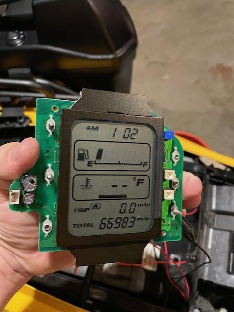
Thanks Grum. I'll look more thoroughly for any F1,F2 items; at a quick glance yesterday I didn't see any. Interesting occurrence today when I went to recheck those voltages at I+G & O+G at the voltage regulator. I got the same reading as above and when I flipped the board over to look at the display, it was fully functioning. So I reinstalled it, the clock was displaying and it worked for a couple key on/off cycles then went blank again. I then removed the unit and wire c;lipped it to the battery but it didn't power on as before. I then checked the voltages as above and got the same readings of 11.5v & 5v so i flipped it back over to check and it was functioning again. I reinstalled the unit and the clock was displaying and I left it for a couple hours. When I came back to it the clock had been functioning uninterrupted during that time. This time when I turned the key on, the display immediately went blank. I think it's interesting that it went from non-operational while being powered to operational while doing the voltage measurements at the voltage regulator. The suggestion to re-solder that component makes sense to me however I think I'd like to replace the voltage regulator at the same time and see how it performs. What are your thoughts about this intermittent functionality under these circumstances? P.S. thanks for looking closely at the board and the main processing chip. I think it may be the lighting in the photograph. Looking at the full size image I'm not seeing any contacts but the next time I have it out I'll look closely. Thanks!
-
LCD Display went out. Need a little assistance.
YosemiteVFR replied to YosemiteVFR's topic in Electrical
Yep those voltage measurements were done in just that way. Continuity checks were done without anything connected to the board. I may have misunderstood something when you said, "You could also do a continuity/ohms check to ensure the Regulator Ground and Input legs have continuity to the 12v and Ground main terminals" and so performed the tests based on what I thought you meant there. I'll double check the initial voltage measurements in light of the continuity test results. -
LCD Display went out. Need a little assistance.
YosemiteVFR replied to YosemiteVFR's topic in Electrical
Presson - thanks! I appreciate your suggestion. Grum! I can't tell you have how much I appreciate you sticking with me on this!! As I understood your recommendations, this is what I did and observed (with the solder joints as they are and not resoldered): (Battery was just off the tender and measured 12.96v) Voltage Measurements (Clip leads between the following: Battery positive terminal to 12v "IGN" & "Batt" terminals of PCB. Battery Negative terminal to Ground terminal of PCB) Voltage regulator: legs I + G = 11.66v Legs O + G = 4.96v Continuity/Ohms Measurements Voltage Reg G leg + PCB IGN terminal = OL Voltage Reg G leg + PCB Batt terminal = OL Voltage Reg G leg + PCB Ground Terminal = 0.1 Ohms Voltage Reg I leg + PCB IGN terminal = OL Voltage Reg I leg + PCB Batt terminal = OL Voltage Reg I leg + PCB Ground terminal OL Can you confirm that I understood your measurement suggestions correctly? And if so, it looks to me that the Voltage regulator voltage measurements are low and all but one of the continuity checks failed. Would I be incorrect to think that these results point to just a faulty voltage regulator and/or its solder connections? Again - thanks so much! I appreciate your earlier calling to attention the regulator. At that time, I was under the impression that it had checked out but I'm going to specifically ask the shop if this component was tested in this way. Much appreciated; there is hope once again! I'll post the results as they come. -
LCD Display went out. Need a little assistance.
YosemiteVFR replied to YosemiteVFR's topic in Electrical
After replacing the component, which is called a Power Management Integrated Circuit (PMIC), unfortunately the display is still not functioning. It's the smaller rectangular chip on the left with 7 connection points along each length. I've been looking into used replacement PCBs (nothing so far), opinions from other electronic repair shops, etc. I confirmed the dealer wouldn't be able to do anything given the fact that the PCB is NLA and they would only replace the board. The bike in my opinion runs warmer than it should and so riding without a coolant gauge is concerning. After addressing the low hanging fruit, I'm left with the 5 year old OEM thermostat as being a likely culprit. Since I refuse to let the display issue keep my from riding the bike, I'm going to install in the meantime a unit from Trail Tech to give me an idea of coolant temps. I wanted something that didn't require me to cut into a hose and while this is going to pick up the temp from the radiator and not from the coolant in the engine, it's very quick to install and gives me something to monitor while riding. This is what I decided to go with while I'm resolving the display issue: Trail Tech TTO Temperature Meter Radiator Fin Sensor I'll post further updates as they occur.