kostritzer
-
Posts
288 -
Joined
-
Last visited
-
Days Won
3
Content Type
Forums
Profiles
Gallery
Blogs
Downloads
Events
Everything posted by kostritzer
-
Probably in the tank, most likely part of the fuel pump module. Pretty much every modern car(and I assume bike) does it like that now, no more external filters unless its a diesel.
-
+1000!
-
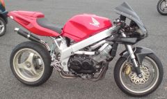 Great looking bike, love the simplicity. Are you running a fuel pump, or gravity feed?
 -

ultimate frankenviffer? Rick Oliver's RC30 with a 3rd gen engine swap
kostritzer replied to kostritzer's topic in Modifications
Well, he does already have a nice RC30, I figured this one was just a fun track bike built on the cheap. If he put an RC30 engine in it then the value would definitely go up. -
ultimate frankenviffer? Rick Oliver's RC30 with a 3rd gen engine swap
kostritzer replied to kostritzer's topic in Modifications
Maybe ultimate frankenviffer was a little bit of an exaggeration. Rick definitely could have gone further with the bike, but it looks like he was trying to put it together without spending a fortune on it. That being said, I'd love to see this bike with everything HondRV4 has done to his bike on it. I have to believe the RC30 frame is a better base for a track bike, but as I haven't finished my 4th gen track bike I don't know what weaknesses it will have or if I'm even skilled enough as a rider to notice them. As for the breather, in the article it says seat or tank clearance was the issue as either the heads and/or valve covers are taller on the 750F engine. -
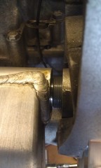
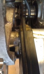
Hi, Thanks for your reply, I have an NC30 swingarm, from what I have read the nc30 spindle will fit directly into the 4th gen swingarm so shouldn't be a problem. I'm aware of the problems getting tyres to fit, but love the look of the original wheel, plus I;m doing an RC30 replica so trying to get as near as possible to the original look. Thanks for the offer of photos, I will probably take you up on that! The eccentric will slide into the swingarm, however it is narrower by about 10mm if I remember correctly. I know VFROEM on here has done it, but I'm not sure how he made up the difference. An RC30 eccentric is supposed to be a direct fit, you only need to modify the caliper mount/stay from what I've seen.
-
4th Gen Project - VFR750RR
kostritzer replied to jeremy77's topic in Third and Fourth Generation VFR's
So are you planning on riding this bike on the road, or is this to be a track only bike? -
to all the frankenviffers, this one's mine, VFR750RR
kostritzer replied to a topic in Third and Fourth Generation VFR's
Extruded aluminum could work. I actually bought some aluminum angle from a local hardware store last year, but when I got it home it became obvious that it was most certainly not straight! I've been thinking about using some lasers as well, really what I need is free time to fiddle with the damn thing! -
I'd definitely be up for experimenting with them, but its going to be awhile before my 4th gen is back together. Its funny, I actually ran these same coils years ago on my Audi urS4 without doing any testing or comparing of the stock vs. stick coils. The car ran great on them right up until the day I sold it!
-
to all the frankenviffers, this one's mine, VFR750RR
kostritzer replied to a topic in Third and Fourth Generation VFR's
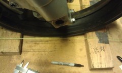
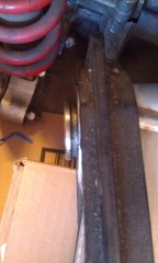
Hey Btec Getting the rear wheel aligned to the chassis is relative easy, although of course there is still a possibility for error due to bent parts. You just have to make sure the rear axle center to swing arm pivot center is equal on both sides. My rear wheel appears to be straight, I didn't measure it with a dial indicator, but it looks very true spinning on the rear axle. Assuming the swingarm is straight, and the frame is relatively straight, then the wheel will at least be square to the rear of the frame. Now at least you have a straight reference going forward to the front wheel, so you just need to center the front wheel to the rear using the string method. If you have an equal distance between the leading and trailing edges of the front wheel to the string on both sides, then you know that the front is pointed straight ahead. Now you just need to measure the difference between the string and edge of the wheel on both sides to figure out how much to the left or right you need to move the swingarm in the frame. Ideally I'd like to use two long certified "straight edges" to do the job of the string, but they're ridiculously expensive! Figuring out chain run after the wheel alignment is a piece of cake in comparison, and at the most would require machining one side of the counter shaft sprocket to get the proper alignment. In reality I probably wouldn't even notice a difference between where my wheel is now or when it was offset 6mm. I'm pretty happy with the way the wheels are aligned now, though I'll double check everything once I get a set of tires mounted to the rims. -
As far as I know all 4th gens and earlier are TCI, not sure about the fuel injected models.
-
I didn't see anything written about resistance of the stock RC51 coils in that thread(kinda skimmed throught it), but Thorsten Durbahn mentioned on one page that the RC51 and RC30 use a CDI box instead of a TCI like our VFR's do. Apparently they've been using the stick coils on the RC51's with good success. The concern is potential damage to the ignition box or coils over a long period of time. This may be one of those thing where someone is going to have to be the guinea pig and try it out. If my bike were together I'd be more than willing to try it.
-
We're definitely going a bit off topic here with this. The V-angle definitely makes a difference as to where the pistons will end up in their respective bores. If you look at the first picture with the crank laying flat, and imagine two of the rods on the same journal are facing down and the other two are facing up, it would lead you to believe that one piston would be at TDC on each bank at the same time. The problem is that the crank is laying flat, which it wouldn't be in a V engine with one piston at TDC. The other crank journal would need to be pointing in the same direction as the bore, and the only way for it to do that is if the crankshaft journals were 90 degrees of each other, or V shaped if looking at it from the side as opposed to flat like the 180 crank or all inline like a 360 crank. Here's an awful pic of a 750 short block with one piston at TDC, and none of the others at TDC. I'm sure someone has a better one.
-
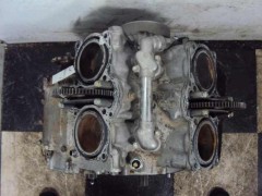
From the album: 4th gen track bike project
-
-
-
I don't see how this would work on any of the 180 degree motors as one piston will always be at BDC when the other is at TDC per bank. I could see how it would work on a 360 degree motor though. When you 'twin-twingle' the V4, your pairing changes from across the bank to across the V... so you do in fact get both paired pistons at TDC at the same time. Whether this is relevant to the discussion I'm not sure - I am only about 80% up on the content here so far, but will learn more because I want to run a coil on plug set-up too :) You really can't have two pistons at TDC at same time with a 90º V4 with a 180º crank no matter how you you turn the cams. The piston position depends solely on the crank and the v-angle. So I can't see how that would work without changing the crank to a 360º or 90º one (which doesn't exist to my knowledge). You're right, the piston diagonal to the one at TDC would be about midway through its stroke, so no paired cylinders. It would have to have split crank journals allowing it to fire every 90 degrees, or it would have to be a boxer engine.
-
Ok, well I could see how it would work like that. I wonder if this setup would cause some interesting vibrations... Kind of a poorman's biggish bang. Do you have any links to the one you've seen?
-
Does the 5th gen definitely use a CDI? I know the 4th gen is TCI. I was under the impression that most ignition systems using the COP's were CDI, and that we're trying to figure out how to use the COP's with a TCI.
-
I don't see how this would work on any of the 180 degree motors as one piston will always be at BDC when the other is at TDC per bank. I could see how it would work on a 360 degree motor though.
-
Yeah, but I think Jeremy was asking if it were possible to use a two coil waste spark setup like the one you posted a picture of to eliminate two of the factory coils.
-
Of course given the fact that the coils are firing twice as often, they may last half as long or potentially overheat, but I doubt it.
-
so implementing this setup (which I think is a late 90's CBR600 setup would convert the 4 coil system on a 4th gen to a 2 coil, wasted spark system, essentially doubling the number of sparks in each cylinder per revolution? This could be really useful for those of us fightering our VFRs to reduce the number of coils to relocate. Of course figuring out the COP option would be even better. Yes, you should be able to in theory.
-
here's a good pic stolen from another site that should explain it pretty well, you just have to ignore how the wires are labeled in this pic. Basically the green negative wire going to cylinder 3 would go to the cylinder #2 and #3 ground/driver wire on the VFR harness, and the negative yellow wire going to cylinder 4 in this pic would go to the cylinder #1 and #4 ground/driver wire in the VFR harness. That is assuming cylinder's 1 & 4, and cylinders 2 & 3 are companion cylinders on the VFR engine, which I'm pretty sure they are.
-
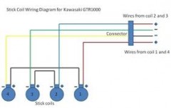
From the album: 4th gen track bike project
-
well, my ms paint skills are pretty lacking. I'll try to draw a picture(artistic skills also lacking) when I get a chance, scan it and post it up. In the meantime, if you look at a 4th gen ignition wiring diagram, you'll see two wires going to each coil. One wire is switched ignition, the other is the "ground" circuit which is controlled by the ignition driver in the TCI. There are 4 drivers, one for each coil/cylinder that are actuated in the firing order of the engine, which I can't remember off the top of my head. The reason you want to wire them in series is so that you add up the resistance of the two "stick" coils so that it equals the same amount of resistance of the original factory coil. To do this, you're going to have your switched ignition wire going into one terminal of the paired coils, then on the other terminal of the same coil, you'll run a wire to the other coil, then you run your ignition driver wire to the other terminal on this coil... Ok, a pic would definitely help here.