BartmanEH
-
Posts
172 -
Joined
-
Last visited
-
Days Won
2
Content Type
Forums
Profiles
Gallery
Blogs
Downloads
Events
Everything posted by BartmanEH
-
I ordered a set of AllBalls Racing tapered bearings and I'll install them when they come in. Before I committed to buying these, I wanted to see if I could get the free play out of my front end by torquing down the steering head bearings a bit more than the punch and hammer method now that I have a special socket tool that fits the adjusting nut. Well I ended up cranking them down a lot with my special adjusting nut tool, socket wrench.... and breaker bar extension. I never did get the free play out despite really torquing them down. I was convinced that I should be able to eliminate the free play. When the adjusting nut was torqued down super tightly, the steering was far too stiff and I could feel the infamous notch. Clearly the bearings are shot and I'm glad I have the AllBalls Racing set on order. I have backed off the adjusting nut to make the steering feel normal again and, of course, still have front end play. In hindsight, after reading some more, I suppose I'm lucky that I didn't crack the bearing race seats in the steering head of the frame. That would be pretty much catastrophic and would require a new frame since I don't have the wherewithal to repair an aluminum frame. Phew!
-
Hey Warren, exactly which one did you buy? Right now on eBay I don't see any carbon fibre ones from Spain. I see one from Bluebird Engineering in the UK but it doesn't look as long as yours and I'd prefer a longer one like yours.
-
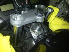
I tightened up my steering head bearing last night. I had noticed before that under hard braking I could feel and hear the front end chatter. That was my first clue that the bearings were too loose. I jacked up the front end last night and jostled the forks to get a feel for the amount of free play in the bearings - quite a bit. I removed the handlebars and top bridge (which is a pain with the Powerlet in there). When I bent down the lock tabs I found the lock nut completely loose. The adjusting nut was snug though. I don't have a proper tool (yet) so I tapped the adjusting nut tighter with a screwdriver and hammer. I'd tap it tighter a bit then check for how much front-to-back free play they was in the forks with the front end jacked up and by yanking on the bottom of the forks. In the end I was hammering very hard on the screwdriver to get the nut to turn just a little and eventually gave up because I was damaging the nut too much. There's still some free play in the forks. In my experience, bearings are set properly when there's no free play and smooth operation. Well, they're smooth still throughout the range of motion of the steering but there's still some free play I don't like. My guess is that I cannot get enough torque on the nut with the screwdriver/hammer method to cinch down the bearings properly. The spec is 18 lbf-ft which should be awfully easy to achieve with the screwdriver and hammer tapping method but I have not been able to completely eliminate the free play. I've ordered one of these to help with making adjustments in the future - Cycledude's (Mike Judnic) Honda steering stem nut socket tool: http://www.ridersral...php?f=4&t=24212 What's the consensus here on fork front-to-back free play? Should there be a little or none at all?
-
From the album: Steering Stem
-
OK looks like the mods have been cleaning up the threads/posts and have combined everything into this thread - thanks, I think. Having done some more research, I question the value of these homemade or aftermarket steering nut socket tools. It seems to me that you need to snug that nut down finger tight plus up to a 1/4 turn more until the lock washer tabs can be lined up and bent up and down to lock the nut in place. What is the point of torquing it with any sort of special tool if you then have to move the nut one way or another to get it to line up with the tabs of the lock ring anyway? Might as well use a C Spanner or tap it with a screwdriver and hammer I'd say.
-
Can someone confirm the socket size needed to make this?
-
Mine feels OK through the whole steering travel - no play to speak of when I try to move the forks front to back either. Such a pain to remove handlebars and top bridge just to get at the adjusting nut.
-
The question: How do you adjust the torque on the steering head bearings? Background: I've read through a few threads about replacing the steering head bearings with the tapered All Balls ones. I'm not ready to jump into that amount of work right now. I do have a shimmy at about 50mph and I would like to tweak my steering head bearings to see if it helps. The FSM doesn't really have a procedure to adjust the bearings - just to RE and RE the whole assembly which involves removing the forks, using a new lock washer etc. If I just want to play with the torque on the steering bearings, what is the minimum amount of dissassemble/reassembly I need to do to get at the correct adjusting nut? How reusable is the lock washer with its tabs you have to bend to secure the adjusting nut?
-
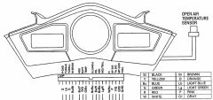
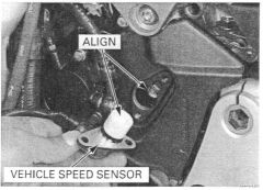
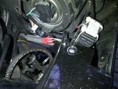
 Jon, I'm revitalizing this thread. Tonight I rewired my SpeedoHealer as you suggested. I do feel better about the concept that the ECU will now be getting the stock unmodified signal as it was designed to do and the corrected SpeedoHealer signal now runs just to the instrument panel and speedometer. So, first of all, a huge thank you to Jon (Coderighter) for his excellent research on this and for sharing his great solution. The only thing I did differently is that I removed the pin from the instrument side of the light grey connector and soldered my new wire directly onto the upper part of the pin contact where the original pink wire is crimped. This way I can remove the heat shrink tubing, desolder my added wire and return the pin contact into the grey connector and restore the factory wiring. My concern is, having now split the speed sensor signal into the ECU and the SpeedoHealer, if this signal is not designed for a high impedance input, I have just increased the load on this signal. I mean, if the speed sensor's output is a whimpy hall effect type signal that requires special receiver circuitry for amplification etc., then I have just seriously compromised the circuit and, hence, the reliability. Now I am inclined to research the speed sensor and what type of signal it generates. The Honda FSM refers to it as the VSS (vehicle speed sensor). It is maybe a magnetic field anomaly detector or similar. It doesn't touch anything but rather is positioned very close to the front sprocket's teeth and detects them as they whir around. As such, it seems to be a rather delicate signal. Power is applied to the VSS, along wi reference ground, and it generates a modulated gentle signal of some sort. I wonder how delicate this signal might be and whether it might be affected by the apparent load of the SpeedoHealer's corresponding signal input circuit which, like the ECU, would be designed to amplify this wonky special signal of the VSS. Meh, that's just the anal retentive electrical engineer part of me over analyzing and worrying. Bottom line is, if it works, it works! I'm gonna have two fingers of scotch right now to calm myself down :-)
 -
BartmanEH and Speedball73 dress up as CHiPs' Ponch and John for Halloween
-
-

From the album: Halloween 2011
-

From the album: Halloween 2011
-

From the album: Halloween 2011
BartmanEH and Speedball73 -

From the album: Halloween 2011
BartmanEH and Speedball73 -

From the album: Halloween 2011
The original CHiPs TV Series featured Ponch and John. We've kinda extended this to, well, Ponch and John... and John. -
-
-
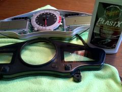
From the album: Combination Meter
-
Version 14 NOV 2012
1,841 downloads
There are several really great and easy to use online microfiche websites. However, when it comes to finding a part and you're unsure of exactly which microfiche its on, it can be somewhat difficult to find. I wanted an offline microfiche and parts list document that was searchable to find what I needed or take with me when I'm working on the VFR. I couldn't find one anywhere so I thought I'd make one from the printable versions of the online ones. Well, this turned out to be much harder than I anticipated. After countless hours of downloading, saving pages, editing them for readability and compiling them into one document, the result was a nice straightforward searchable document. I thought I'd share my efforts in case others found it useful. This document is specifically for the 2006 Honda VFR800A Interceptor ABS (note that it's the ABS version - lots of extra brake plumbing!). It even includes the Evap Canister stuff for the California model, even though mine doesn't have this. The usual disclaimers apply. Before ordering anything and when in doubt, consult the latest online versions - there are superseded part numbers that come out from Honda all the time. Don't be shy, feel free to post questions at VFRD - there's a lot of helpful members here. Enjoy! -
It comes with thin double-sided black foam tape. Seems to work well. I wouldn't expect that it's re-positionable. However, it does come with an extra piece of tape for re-positioning once.
-
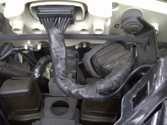
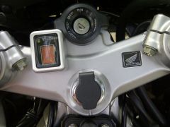
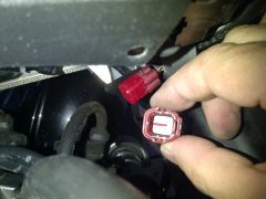
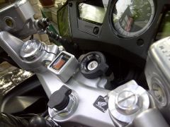
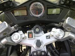
This is my review of my new HealTech GIpro DS gear position indicator (GPI). A couple of years ago, I installed an Acumen DG8 GPI. Recently I've become jealous of HealTech's new GIpro DS GPI. I've heard that it has less lag than anything else on the market - hardly any, supposedly - and it connects easily via the diagnostic connector we have (AKA the DLC). I've got HealTech's SpeedoHealer installed and it's a fantastic piece of kit. The company is great too. Whenever I've ever fired over an email question, Norbert's come back promptly and courteously with a reply. Their customer service is exceptional. I finally couldn't stand it any more and broke down and bought one. Here's my review complete with photos of the de-installation of the old Acumen DG8 and the installation and testing of the new HealTech GIpro DS. I mounted the ol' Acumen GPI on the triple clamp (AKA yoke) and it looked pretty good, by-and-large: Acumen DG8 gear position indicator mounting location I always prefer modifications that don't affect the factory wiring harness. Acumen's harness adapter allows for the connection of the DG8 GPI in between the combination meter and its mating harness. It's bulky, it works, but I've always been worried that water would get in there. Here's a picture of the Acumen loom (harness) adapter installed in my 6th gen VFR: Acumen loom (harness) adapter If you look closely, you can see the original factory wiring harness connector's rubber boot was uselessly covering the harness end of Acumen's loom adapter. Both ends of the loom adapter were exposed to the elements. I taped it up with Magic Wrap as best I could but it was far from hermetically sealed. From the factory, Honda has the nice rubber boot covering the harness connector and rather hermetically mated to the white lip you can see at the combination meter end. So while Acumen's loom adapter doesn't require modifying the factory harness per se, it does compromise the overall integrity of the all important combination meter wiring. OK, time to rip it all out. Off comes the windscreen. Off come the left and right meter panels (argh, they're a pain-in-the-neck to remove, always feels like I'm gonna snap those precious Pearl Cosmic Black painted ABS parts). Off comes the combination meter plastic cover (argh, PITA to remove due to super tight rubber grommets at the bottom). Disconnect and remove the Acumen loom adapter. Replace the factory harness back to stock with its integral rubber protective boot. Ah.... that feels better already. Re-install the center meter panel, the left and right meter panels, the windscreen. Phew! What am I at now, about an hour, probably more. I like to take my time to help ensure I don't break anything. It was a time-consuming installation and a time-consuming removal. So much for the Acumen DG8 GPI. Let's get on with the installation of the HealTech GIpro DS GPI. Per the included instructions, locate the DLC: DLC connector (red) location behind right meter panel In the photo above, I still have the right meter panel removed. It is not necessary for the right meter panel to be removed. The DLC can be accessed with the VFR fully assembled by design. Next step, remove the DLC cover: DLC connector cover Not being the best photo journalist, you may have noted that the DLC cover had already been removed in the previous location photo. By now it's getting dark and starting to rain. I hurried the rest of the job and didn't take any more photos of the installation. Well there's not much to show anyway. Just connect the harness end of the GIpro DS to the DLC. It's got a nice gasket inside it just like the OEM red cover. Should keep all the crud and corruption out of it quite nicely. Lastly, mount the indicator in a appropriate location. Here's my first location - still under consideration: GIpro DS location It's nice and small and fits rather well there up on the instrument panel right next to the tach. Just a small section of unobtrusive cable showing for it as it runs from the display up under the meter panel and across to the DLC. Certainly easier to see than the Acumen's location choices which were restricted by the fact that Acumen's DG8 has its cable coming straight out the back of the unit near the top edge. The only thing I'm not happy about with its current location is that it is slightly off angle and facing slightly off to the left. The meter panel is beveled from the middle sloping outward slightly to each side. Thus, the GIpro DS is not facing me square on. This really doesn't affect its visibility in any practical way but it is slightly distracting to me - or should I say, aesthetically detracting to me. Yeah, I'm just that way. The good news is that HealTech had the foresight to anticipate that some customers may be suffering from OCD like me and thought to include an extra double-sided mounting tab so that the unit can be relocated using their high quality adhesive tape. I'm thinking about making a thin beveled adapter to counter the taper of the meter panel cover (did I just say that out loud?). That's not something I'm gonna rush off and do. It can wait.... until I can make the sweetest of adapters that's perfect in every regard! So how does the GIpro DS GPI unit operate? How well does it work? Well, programming was a breeze. Upon power up, it does a little fancy count down and sits there with a big "L" on the display. "Learn" mode, I'm guessing. This behavior is not documented in the manual. I don't think they really expect people to power it up in an unprogrammed state for long. As soon as you spark up the engine, the display starts blinking "1" per the instructions. Programming the unit is fairly simple and goes by the book from this point. I find it hairy to program GPIs with the bike on its center stand and running up through the gears. In theory it could be programmed while riding but I'm unsure about how it would react if programming were interrupted by having to gear down part of the way through programming the gears due to normal driving requirements like traffic etc. I'll try it sometime so we all know [EDIT: subsequently received a note from Norbert at HealTech that there's no problem programming the unit by riding - you can even shift down and stop part way through the programming] but in this case, I programmed it on the center stand. I ran it up through the gears at above idle per the instructions. It takes quite some time to program the gears, particularly the lower ones. The whole time, while struggling to hold a reasonable RPM (as some of you know, that can be a challenge with the snatch throttle of the VFR and its infamous surging problem), the drive chain is slapping around with no real load to quiet it and the bike is bucking around a bit as well. Whenever I program a GPI, I park the bike facing up a slight uphill. That way it sits back pretty hard onto the center stand. A bit more secure that way. I also face it as close as possible to a wall and chock the front wheel. That way I hope to limit damage should the bike launch itself off the center stand. Like I said, its pretty hairy and I prefer not to do it every day. Whatever you do, just stand beside the bike for this procedure and don't sit on it - you don't want to do anything that may cause the rear wheel to hit the ground while you're in 6th gear and ~3,000 RPM. Now that the unit was all programmed, I took it for a ride. I can tell you that the GIpro DS is quite a bit more responsive and less laggy than the old Acumen DG8. It indicates lower gears in under a second and upper gears well under a second. The old Acumen DG8 took almost 2 seconds to display gears. This is pretty impressive. Also, in my short test rides thus far, I've had no false gear indications. The old Acumen DG8 would occasionally display the wrong gear and then would correct itself after, say, 2 seconds. The new GIpro DS is proving itself to be quite the marvel of technology. The HealTech crowd really does make high quality stuff. Major advantages of GIpro DS over Acumen DG8: unobtrusive cabling installation - slips right on to DLC without disconnecting any wiring or connectors whatsoever easy installation - in addition to easy cabling, no removal of anything is technically required although you may wish to in order to route and stow the cable ultra fast indication - shows the correct gear in under a second which is more than twice as fast price - the GIpro DS is $150 whereas I paid $210 for the DG8 display, loom adapter and billet aluminum housing customer service - lightning fast responses to email by HealTech, not so much by Acumen That brings me to my conclusion. I'm very pleased with the HealTech GIpro DS gear position indicator. For me, it was worth the re-investment for this add-on mod for my VFR. Anyone looking to add a GPI should consider the HealTech GIpro DS and look no further.
-
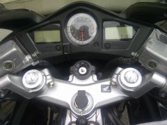
From the album: Gear Position Indicator
-
-
-
From the album: Gear Position Indicator
-
From the album: Gear Position Indicator
-
From the album: Gear Position Indicator