BartmanEH
-
Posts
172 -
Joined
-
Last visited
-
Days Won
2
Content Type
Forums
Profiles
Gallery
Blogs
Downloads
Events
Everything posted by BartmanEH
-
From the album: Starter Valve sync 18 AUG 2014
-

Starter Valve sync 18 AUG 2014
Images added to a gallery album owned by BartmanEH in Member's Gallery
-
-
From the album: Starter Valve sync 18 AUG 2014
-
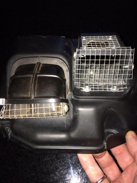
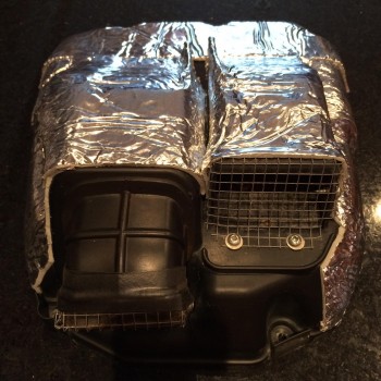
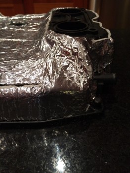
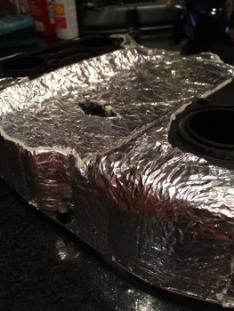
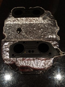
I went ahead and insulated the top of the air box too: I'm planning to get a dyno tune for my Power Commander 3 and this seemed like a cheap and easy mod to help get cooler and hence more dense air into the air box.

-
From the album: Air Box
-
-
-
From the album: Air Box
-
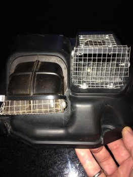
No water will enter the air box, mine has never had any water in it. It has been gone for almost 5 years..There's no doubt that water enters the air box: This photo was taken after a 9 day ride around Lake Superior that included gravel roads in the rain. The dirt and gravel dust covers the entire flapper shelf and snorkel innards and extended a bit around the inside of the lid of the air box. It's been cleaned which is why you only see the dirt in the not-easily-accessible parts. After my ride around The Rock (Newfoundland) in 2012, I cleaned out fine gravel from around the air filter which was dragged in through the snorkel and de-flappered vent. I'm sure Honda designed our bikes to handle some drops of water etc.
-
Water does get in air box - the residual dirt proves it
BartmanEH posted a gallery image in Member's Gallery
From the album: Air Box
-
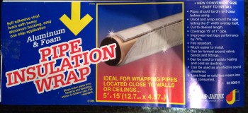
Vinyl foam aluminum backed self-stick insulation
BartmanEH posted a gallery image in Member's Gallery
From the album: Air Box
-
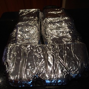
Like this? I did the bottom half of the air box today. Not sure I'll bother with the top which is pretty much getting enough cool air on it.
-
From the album: Air Box
-
From the album: Air Box
-
bottom half of air box covered with insulation:
BartmanEH posted a gallery image in Member's Gallery
From the album: Air Box
self-stick 5" x 15' vinyl foam aluminum backed self-stick insulation -
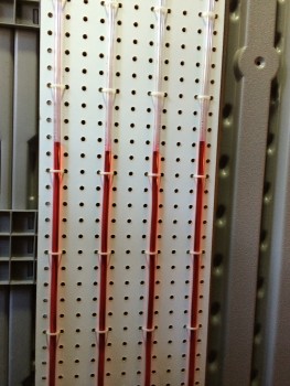
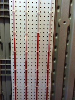
This is a repost of my original post of June 16, 2008 since I cannot find the original post anymore (VFRD problem?) I’ve been suffering from the reasonably well documented surging problem with my 6th gen 2006 VFR. At small throttle openings, the bike was surging. In neutral, I could not get it hold any steady RPM in the 2K-3.5K range. It’s not my wrist as I have a throttle lock and it does this with the throttle lock engaged too. This has been pretty well documented on the Honda VFR Club (UK) site in the thread “Vtec fuelling/throttle control problem - a new hope.” (http://www.bikersoracle.com/vfr/forum/showthread.php?t=44763). This is a painfully long thread with 460 posts and some 31 pages long spanning April, 2005 to today. I’ve worked my way through it a few times and, like any long thread, it goes off on tangents and comes back once in a while. Reading it did convince me that my surging problem could be somewhat reduced, if not eliminated, by synchronizing the Starter Valves. After seeing Darth Bling’s great DIY differential manometer for synchronizing Starter Valves (http://www.vfrdiscussion.com/forum/index.php?showtopic=16200), along with some other brave folks, I thought I’d have a go at this. I decided that the right thing to do for my bike is to sync them flat – the overwhelmingly favourable conclusion for the VTEC (as opposed to the pre-VTEC which has offsets in the sync). This is good news for us VTEC owners because it means that you don’t need any accurately calibrated absolute vacuum gauges for this job, just a simple differential gauge. This is where the homemade DIY differential manometer idea really shines. I also decided that I would keep as much as possible connected and operating during this procedure. The service manual would have you disconnect the PAIR valve and plug the reed valve cover. Other various guides and posts would have you also disconnect the MAP Sensor (sometimes), disconnect the IAT Sensor, disconnect the Variable Air Intake Solenoid, etc. Some posts complain that the idle cannot be adjusted once these various items are disconnected and other posts complain that the settings like idle and probably Starter Valve sync change after reconnecting everything. So I figured the best way to keep as much connected as possible so that the bike was operating as close to normal as possible. I set about collecting and purchasing the bits and pieces for my version of the DIY differential 4-way manometer: 45’ of 3/8” O.D. 1/4” I.D. vinyl tubing 3 x 1/4” TEEs 3 x 1/4” elbows 1’ x 4’ white peg board 5 x 1/8”-1/4”-3/8” adapters ~1 cup of ATF oil 4 x MIG welding contact tips with 0.025” wire hole ~50 tie wraps Neatness counts. That’s just my opinion. Furthermore, I plan to use this jig again in the future so I wanted it neat, storable and functional. Notes: ATF because it has a nice red colour for contrast ATF because it is viscous enough to assist with damping the pulsating vacuum from the throttle bodies White peg board for contrast with the red ATF Peg board because it’s cheap and has nicely spaced holes for the tie wraps White peg board for good contrast with the red ATF 1/4” I.D. tubing so it was substantial enough to resist kinking MIG welding tips with smallest available hole to be used as dampers as they fit perfectly inside the tubing Constructions details: I used 10’ of tubing for each of the four manometer lines for each of the four throttle bodies. I wanted to be sure that I would have time to shut off the bike before any ATF got sucked up into the throttles should something go wrong. Also, the longer the line, the more vacuum pulse damping there would naturally be, albeit minorly at the expense of response time. Here’s a close up of one of the MIG welding contact tips inserted in one of the four lines: Here’s a picture zoomed out showing one of the 1/8”-1/4”-3/8” adapters at the end of line ready for connection to the throttle body vacuum line. I wrapped the joints - where I cut the tubing to put in the MIG contact tip dampers - with Magic Tape to make sure there was a good seal there. Magic Tape is really great stuff and I use it all the time. It turned out to be really necessary for other joints in my jig which I’ll get to later on. Once I had constructed the main jig and successfully got four lines attached to the peg board, I decided that the best way to keep the MAP Sensor enabled/connected was to tap off one of the lines with another TEE to make a fifth vacuum connection to go the MAP Sensor. I tapped of the #4 manometer line since this is the reference Starter Valve and is not to be adjusted in this sync procedure. Here’s a picture: Here’s the bulk of the jig: First things first - tear apart the top of the engine area. I suspended the fuel tank vertically from the roof joists of my shed: I then proceeded to take apart the air box for the first time since taking ownership of this slightly used (~2,600km) VFR in April only two months early. Well imagine my surprise when I found this on top of my air filter: It looks like a mouse made a nest in the top of my air box, probably some previous winter when the previous owner winterized and stored it himself. I’m going to have to write another post about my forthcoming mod to add anti-critter screening to the air box snorkel intake. The nesting material was covering at least 2/3 of the filter area. Granted it was nice fluffy stuff and likely breathed a fair bit and was not completely blocking off that part of the filter but still, there must have been some detrimental effect to that. After cleaning the air filter, I rigged up my jig next to the bike: I disconnected the 5-way vacuum connector and connected up the jig’s manometer lines: You can see the stark white IAT Sensor in the middle. I removed it from the bottom of the air box so I could connect it up. Same with the PAIR Valve, MAP Sensor and the Variable Air Intake Solenoid – all removed from the air box and connected back into their respective circuits. It’s not easy working under the air box to remove the sensors – it’s a tight spot and hard to do even with a stubby Philips screwdriver. I actually did a test run and warmed up the bike without any ATF in the jig. I wasn’t sure if I had everything hooked up properly and wanted to be sure the bike would start and run without risking getting ATF sucked into the throttles. I understand that this wouldn’t be a total disaster but I don’t like the idea of ATF oil coating the throttle bodies, Starter Valves, etc. After a successful “dry” run, I loaded up the jig with ATF about 1/3-1/2 way up the lines, leaving plenty of room for the differential readings. Here’s a picture of the initial readings: The differential between from the reference Starter Valve #4 was so great that I couldn’t get it onto one picture and had to merge two pictures together to show it! I haven’t done the research yet to figure out how an inch of ATF compares to an inch of mercury in terms of pressure/vacuum. However, even without doing the conversion, one can see that the difference is way too much. This is where the fun started. My #3 line had a few leaks in the TEE at the bottom of it. I tried adding tie wraps to no avail. Apparently the <$3 plastic TEEs I had found where not very high quality and allowed air to get sucked into the jig in various spots. Even though they had 4 barbs per fitting joint and I had to use a heat gun on the vinyl tubing to soften it up enough to get over all four barbs, they still leaked. I ended up using Magic Wrap on all the connections to render them air tight. Here’s a close up of the Magic Wrap doing its thing: Eventually I got it airtight enough to be able to take readings, however, I think I need to replace all the fittings before I use it next time because even a small leak, say up at the TEE that splits off for the MAP Sensor, will throw off the accuracy of the whole procedure. Oh well, I’m sure that in the end, I will have made the synchronization much better even with any minor flaws/leaks in my jig. So I proceeded to start synchronizing the Starter Valves. This takes quite some time. You need to iterate the settings of each Starter Valve a lot to bring them all close to synchronized as represented by a level fluid line across the four tubes. Because this is a differential manometer, changing one Starter Valve basically affects all the others. You need to blip the throttle between tweaks to help the Starter Valves to settle in. I manually pulled on the Wax Unit tie rod in the middle of the throttle body area to help reseat the Starter Valves. This causes some disconcertingly loud air escaping sound and hopefully doesn’t damage, anything like the Wax Unit actuator itself, but I found that blipping the throttle on its own didn’t really affect the Starter Valves in any way and didn’t seem to re-seat them satisfactorily. The Starter Valve adjustment nuts are sensitive – just gently pushing on the set screw nut sends the manometer readings soaring – so you want to be sure they’re getting re-seated in their natural resting spot before making further adjustments. Eventually you get a feel for this and eventually I got them to line up something like this: They were closer after some throttle blips and out roughly like this at other times. This is as close as I bothered to set them at 9pm on a Sunday night. Further iterations were making things worse so I left it at this. I also took the opportunity to take out as much slack as possible on the throttle cable. I did this at the throttle body end since it was all apart and easy to access now. I managed to pretty much get all the slack out and tested the full range of motion of the steering to make sure that at either the left or right extreme that the throttle cable wasn’t so tight that it would get actuated purely by the action of steering. Conclusion (A.K.A. test ride time): There is an unbelievable difference with the bike now. It’s like a completely new machine. Firstly the sound – it has a beautiful new roar as you throttle up from idle to 5K. From 5K up I found everything pretty familiar. This new sound I attribute mostly to the cleaned air filter and figure now that the engine can breathe fully, it’s generating more power. The Starter Valve sync might be contributing to this new sound too – with a nicely balanced power roll on, the engine is performing much more efficiently and I would expect this could be audible. Beyond this let me tell you that the small throttle opening surging problem is all but gone. I can coast down to idle in first gear without surging nor does the bike sound like it wants to stall. I can roll on the throttle again with pretty darn smooth response. Neutral RPM test is much better – I can almost any RPMs I choose now – but it still likes to jump up from 2500 to 3000 RPM. This servicing was worth every minute of time it took in preparation and execution. As soon as the bike exhibits the surging again – and I expect it will as it breaks in more – I will be back into it with my DIY jig syncing those Starter Valves.
-
Please search VFRD for info on doing a full PAIR removal - the instructions you linked to leave the reed valves installed which will eventually leak and lead to more problems. The right way is to remove the reed valve etc. and use PAIR blanking plates.
-
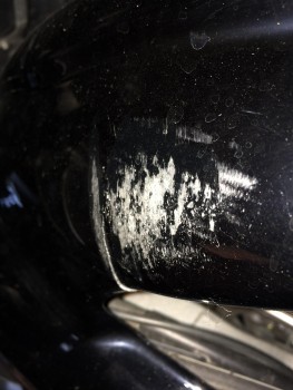
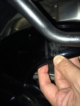
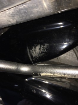
Here's the crack that's developed in my Power Bronze hugger. I think it's hitting the exhaust under load and full suspension travel. It's got over 22,000 km (13,500 mi) on it so I can't complain really.
-
From the album: Hugger
-
-
-
From the album: Hugger
-
From the album: Hugger
-
From the album: Hugger
-
Starter Valve Syncing And Low Speed Throttle Response
BartmanEH replied to HighSideNZ's topic in Sixth Generation VFR's
<sigh> maybe a mod could split out this thread leaving the OP topic of SV sync and start a new thread for all the RB2/3 poo. I'm gonna resync my SV's later this month. If i've got time, I might try staggering them as per the OP but with O2 elims and flat SV's, I've been pretty happy with my roll on throttle response, lack of snatchiness and stead RPM capability in neutral. -
As a follow up to this, I'm glad to report that many thousands of kilometers later, this mod is working fine for me. My concern - stated in previous post - over splitting the signal and creating an additional load on the VSS is unfounded since [1] it's working fine and [2] the original wiring splits the VSS signal into the speedometer circuit and the ECM anyway so it's always had the load of those two circuits. With this mod and and the Speedohealer installed, the load on the VSS is the Speedohealer and ECM instead of the Speedometer and ECM - that amounts to the same thing. We're all good!
-
-