

enzed_viffer
-
Posts
1,047 -
Joined
-
Last visited
-
Days Won
5
Content Type
Forums
Profiles
Gallery
Blogs
Downloads
Events
Everything posted by enzed_viffer
-
I got it working through the high beams. The contacts in my remote acted only momentarily when the button is pressed - the door doesn't continuously open and close if you hold the button down. I assume that's built in the circuitry. I took the two leads from the contact switch straight to a relay which is triggered off the high beam circuit. Even if you run with high beams it's only going to momentarily activate the opener remote. Hmmmm... I'll have to check that wiht one of the other remotes. If it works like that, then I'll be adding a relay to the system and using the headlight flasher, the next time I have the upper fairing off. Now - what can I use that button for.....
-
It should do (test it with the battery in to make sure), but you don't have to unsolder the switch. It'll work just fine with it left in. If you want it out (to save accidental pressing, for example?) then just put a small screwdriver or something under the switch, and pry it gently while you heat the terminals on one side then the other. I left my switch on because (a) it's under the front fairing where there's no danger of accidental operation, and (B) I can revert to using it as a normal remote should I need to - just snip the wires off. Gaaaa!! All this talk has got me wanting to farkle again. I'm thinking of having a go at wiring it through the headlight flasher, and powering it from the bike's battery rather than an internal one. By the way - this isn't my idea, so I can't take credit for it. I copied someone else's initial idea, but just did it slightly differently.
-
I just shorted mine out (with the battery connected) to see which pair it was. One pair worked, the other didn't. In your pictures, I'm guessing that either the left-hand or right-hand pair in the bottom picture will work, given the way they're effectively the same from an electric point of view. I'd go with the left, as it would be easier. If you wanted to come through from the other side, you could poke the wires through the holes next to S1, and bend the wires over to those two, or bridge them across.
-
I did that for 6 years or so. The problem was, sometimes it would twist around in my pocket, so I'd have to fumble a bit to get at the button. Also, I was trying to cut down on the amount of crap I was carrying around in my pockets. I figured too that summat that didn't require me to take my hand off the bars was a Good Thing as approaching my house from either direction puts me on a curve. The main reason I did the mod was just because I could.
-
My initial plan was to wire it up using a relay from the high-beam flasher switch to the opener, but it became too complicated, as I would've needed to use a relay, a timer and some diodes, in order to eliminate the relay being 'live' when using the high beams, as the flasher switch is wired a bit "dirty." So, in the end, I used the KISS principle, and went with the handlebar switch and no relay. It's a shame, as operating a left-handed switch like the flasher is easier than taking my thumb off the grip while riding. Maybe I'll have a look at it again the next time the switch breaks (it's broken once already, as it's not very heavy duty). Still, it works well, and the door opens (from up to about 60m away), so that's the main thing.
-
You know at least a couple of things: 1. It surges between 4.5 and 5.5k rpm. 2. It's surging, therefore it's running lean. 3. This is most likely either an air leak (which you seem to have ruled out), or insufficient fuelling. Before you panic, and sell it or "blow the f$%ker up!", do this: 1. Save your current PCIII map to a different name. 2. Add some numbers to the map in the 4-6k rpm range (to richen it up), save it, and load it. (It sounds like it's just small throttle openings, so start with those first). 3. Go for a ride. 4. If it's not right, then repeat until it's more betterer and acceptable. 5. If for some reason it gets worse (unlikely), then it's actually running too rich, and you need to put lower figures in the map. It's not RocketScience, so it's easily fixed. You have nothing to lose by fiddling around with your mapping, because you've got the saved one to go back to, and it's relatively hard to muck it up, as long as you don't change too many factors at once, keep each change small(ish), and note what you did. If this is all too hard, then you need to have it dynoed with an EGO sniffer.
-
Tim(Avid One),Claudia,Kelly,Me
enzed_viffer commented on teleskier's gallery image in Member's Gallery
 This photo scares me... :wheel:
 -
Addendum: It turns out that I'm not a FeckinEejit after all. Well... at least not in this case. I cut all the heatshrink off the new wiring, and spent some time with a multimeter trying to figure out what the wiring should be for the heated grips. It must be some kind of weird, esoteric DarkVoodooMagic, because the multimeter didn't tell me much. measuring the resistance between two of the wires gave me a consistent reading, no matter what the setting, and the same with the other pair (but slightly different resistance). So I gave up on that, and resorted to swapping wires and testing till the heat-troller behaved as expected. You'd think that (with respect to) the controller, which has three wires (red, green, white/black), red would be power in, green = ground, and white/black=power out. Reasonable? Apparently not. Red=ground, Green=power, white/black=goes into the grips. I'd reasoned that the heattroller controlled voltage in, but apparently it's "Something to do with the earth", like Globular Yawning, or Save the Whales. So after much testing and head scratching, I reversed the terminals on the fuse block, taped everything up, reinstalled the fuse, and labelled the fuse block cover "Socks". Or "Grips". Or "Satan's Little Helper".
-
 Do those brake lines rub on the instrument panel, Rob? I'd guess that given your attention to detail, the answer would be "No". :)
 -
 I like customised bikes. Can't say I'm overly impressed by the look of this though. Still, it's good work, by the looks of him. :thumbsup:
 -
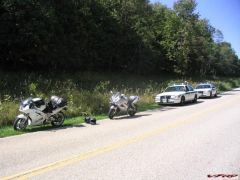 I passed a cop once, about 12 or 13 years ago. Nothing happened, even though I was doing probably 30km/h over the limit. I doubt whether I'd get away with it nowadays. The last ticket I got was just over two years ago - 132 km/h in a 100 zone. $300 and 40 points on my licence. :( Mind you, I had 30 years of ticketless speeding before that...
 -
And now for the bloopers... (Methinx khyron and hawglet won't want me doing any work on their bikes after they read this...) I actually nearly set fire to (and presumably that would've created an explosion) the VFR when I'd finished my wiring install. The battery votage was down, so I went to hook up the charger. The little red blinky idiot light didn't go. WTF?!? So, I wiggled wires and whatnot, and tried the connector with the clippy thingos (technical term). THAT worked, so I decided there must be a break in the wires for the quick-connect doofer (another technical term) as the fuse was OK. When I reached down to plug the cable from the clippy things into the one from the charger, I inadvertantly (it was late, and I was tired, OK?) plugged it into... the .... other connector. Instead. By mistake. This created a nice incestuous loop from the battery back to itself, and within milliseconds, there was a writhing, smoking, black thing, with melting insulation. Ooer!! :o Of course it was now very hot and melty, and because I wasn't wearing my expensive new(ish) mechanic's glubs, it took me several more precious seconds to unplug it. I think it will be OK, but just to be sure, I used my son's charger, which is more betterer anyway (1A instead of 500mA). Now I have another job to do (fixing the charger's wiring) and a warning from my wife to "not fix things when you're tired." Blooper 2 I HAD to ignore the WifeAccountantPorcupine's warning last night, in order to finish the wiring tidy up so I could ride the bike again, instead of passengering for Maniac Driver/BoiRacR/PuddingPimp (aka #2 Son). It took absolutely AGES to slide the heatshrink on the piece of cable with it in place, and even longer to try and fit all the heatshrunk bundles around the headstock, especially as they were much less flexible than when they were merely taped. But, eventually, I got it all in place, and looking very tidy, and whipped the fuse in to test that it all worked. Yay! It works! :thumbsup: And the handlebars still turn, and everything! I'm a star! A winner! A SuperDuperElectricalGod! Or not. This morning, I cranked the bike up (Yay!! It goes!!) and put my gloves on while it warmed up. A horrible, stinkily humid day. Exactly the kind of day you don't need heated grips. Hello... they're getting hot. Check the controller: definitely OFF. Check the grips: they're most definitely getting hot. Oh crap. Pull the fuse, and they start to cool down slowly. At least something functions as expected. So, I now have to cut open the bundle of wires and reverse a couple of plugs that are obviously round the wrong way, bypassing the controller so the grips get full current, all the time. I'm a FeckinEejit. Mebbe my wife knew that when she issued the command to desist from all fiddling...
-
:lol: You didn't see me before I took the first photo, frantically cleaning all the accumulated spooge off everything! My bike looked so clean and shiny when I got it 26 months ago, now it looks much scruffier. But at least it goes better, and is much improved in other areas. :salesman: Your wiring looks OK, if a little busier than mine. I couldn't put my fusebox where your is, as that's about where one of the Fiamms is mounted. I had toyed with the idea of putting the accessory plug somewhere there, but between the speedo corrector and the horn, there wasn't a lot of real estate left. I figured anyway that I'm unlikely to use the plug very much, so under the seat is tidier.
-
Into the accessory socket. (So far used only once, for a borrowed GPS). I didn't realise until I had the seat on and the tail cowl off, just how much space there is under the seat. There looked like there was nearly enough room for my pump, but maybe not with the toolroll in place. I'd like a voltmeter, and the fusebox would be an ideal place to wire it up, but there's nothing that suits me available here, and the function will be taken care of by the digital data centre, once we get the thing built.
-
It IS your bike. I just sneaked into your garage to take the photos. :unsure: No, this is an 'add-on'. It's just for the accessories the bike has. Like I said in the write-up, I was tempted to buy the 12-fuse 5026 unit (which is only about an inch longer), and use it to replace the fuses under the rear of the tank. But I figured it would end up messy, as unlike my install, there's not likely to be any slack in the wires to those fuses, and it would be a cramped place to work and to have to solder extensions to all the OEM wires. I've discovered from past experience (trying to install a speedo corrector at the speedo sender end of the wires) that there is almost no slack or spare length in any wires. It's probably worth doing, but I couldn't be bothered. It took me AGES to do this, as I spent a lot of time standing there with my brain in neutral, gazing aimlessly into space (or lovingly at my bike).
-
Remembering the bit I forgot about... Last night I ripped into the bike again, and with an old razor blade cut open the sticky insulation tape on the heated grip wires. [You guys DO know that there's insulation tape and insulation tape, right? The nong that taped this up should have used the kind designed for wrapping wire looms: it's less sticky, has an adhesive that doesn't get tacky when hot, and it's more durable. :unsure: ] Anyway - this is what I revealed: All that was taped up into a fat bundle that dangled down the side of the steering head. :blink: The positive power input for the heater controller was spliced into the front brake stoplight switch, and the ground went somewhere in the wiring loom under the steering head, probably to the horn or summat. Handy, I guess, but not ideal. Definitely NOT ideal was the 5A fuse holder wrapped up in the taped up bundle. Firstly, it should have been maybe 3A at most, and secondly, it would be very hard to access easily. I cut a couple of feet of wires off, rerouted the cable for the controller so it no longer had an acute bend in it, and ran a new cable from the Blue Sea fusebox along under tank on the the left side and through below the headstock, zip-tieing it along the way. I removed the splice into the brake switch, and resoldered it where it was originally cut, covering the join with two layers of heatshrink. Though it was tempting to 'rationalise' the mess of wires, I decided to leave all the original bullet connectors in place, and merely covered them with heatshrink and zip-tied the results out of the way. Now I just need to write a "GRIPS" label for the fusebox, and buy a suitable fuse, and I'm done. For the time being. Until I think of some other electrical farkle to add. :salesman:
-
Good stuff! :thumbsup: Make sure you keep us up with the play, Riv!
-
Yeah, but it would be distracting for the rider (if used for indicators) or not good for your night vision if used as pilot lights.
-
Indeed! It's like, "Look - here's this REALLY kewl stuff I did to my bike", and then "BAM!" - it's all gone! And when you look at him standing next to a comprehensively trashed bike :pissed: Broken into bits, no less... :goofy:
-
Blue Sea Fuse Block and Relay I'd been intending to tidy up my wiring 'sometime', and needed to fiddle with the VFR. With the aborted purchase of a new windscreen, there was now a hole in my fiddling schedule, so I decided to move the wiring tidy-up forward to this weekend. I'd already decided what I wanted, and where to get it. There's a marine services place a few blocks from my new workplace, and I knew they were stockists of the Blue Sea products, and that they had the 5205 in stock. The 5205 fuseblock is ideal for the VFR, as it has a negative bus, so accessories can be wired solely to the fusebox, instead of hunting for likely places to ground electrical items. Furthermore, it is very compact, robust, and well thought out. I had toyed with the idea of buying a 5206 instead, with 12 fused connections, as it is only slightly bigger and would still fit under the VFR's seat, but decided it was unlikely I'd ever have more than 6 items needed a fused connection. I also toyed with using the 5206 and moving the existing OEM fuses to it, but decided that would open a big can of worms, with having to lengthen bits of the wiring harness and whatnot. It hasn't caused any problem to date, so I left it alone. So, here's the underseat area pre-install: Here's what needed to go under the seat: "The bits" included an accessory socket, fuse box, quick-connect plug for my battery charger, and a relay to hook the fusebox to the battery via the ignition circuit, so it would be active only when the key was in the "ON" position. I'd previously installed dual Fiamm AM80 Super horns (in conjunction with the OEM horn), but had neglected to put a fuse in, knowing that 'sooner or later' I'd get round to doing this fusebox install. The R/R fan (see below) had a fused connection in the tail cowl, where the fan ran off the taillight. I removed the fuseholder and negative connection from the tail, and used the positive one as the trigger for the relay. Here's a pic of the R/R fan: I personally don't think the fan will prolong the R/R's life significantly, but installed it because (i) I like to fiddle, and (ii) we had a heap of them lying around in our basement. It's screwed (into holes I drilled in the R/R heatsink) using two 50mm stainless screws at the top, and held at the bottom with a zip tie. I toyed with the idea of mounting the accessory plug (cigar lighter socket) into the fairing, and also with using a marine power socket instead, but decided that I liked the idea of having the power socket stowed under the seat, because it meant I could locate it wherever necessary on the bike (like in the tankbag) for items like a GPS, or have it under the seat in wet weather. Also, rather than have to get an adaptor for things like my tyre pump, it was better to stick with the socket I had. Saved money too... All the connections I made were crimped and soldered for security, as I'm not a great fan of the effectiveness of either of my crimping tools. The relay was a standard 30A horn relay, with 40A capacity. Rather than risk problems with shorts or water ingress (and to save time!), I used a pre-wired relay base plug, but used a jeweller's screwdriver to slide the 'power in' terminal out of the holder, levered it open, and replaced the wire with a thicker one with a waterproof fuseholder and 30A fuse. I soldered it up, and slid the terminal back into the holder. I then zip-tied the holder to the relay, and covered the two with a length of bicycle innnertube. The fusebolck is bolted to the undertray with stainless steel machine screws, with blue Loctite on the nuts. I had to cut two of the tabs on the undertray (used for a Honda U-lock) with a sharp knife to get the fuseblock where I wanted it. Here's how it all looks installed: After I took this photo, I added a plastic shield to the crossbar under the seat, to stop the tool roll sliding into the wires to the rear of the fusebox. I constructed this from a cut-up black polyethylene icecream container, zip-tied to the crossbar. Having the tail cowl off was also an opportunity to give things a good clean (the tail cowl was covered underneath with chain spooge and dirt), and to fix a few niggling things, like a missing grommet between tail cowl and taillight, and fit a new ground for my taillight flasher. I also replaced a taillight bulb (twice!) when I discovered one taillight wasn't going. Luckily the indicator bulbs are identical! The install all went pretty well, except after I'd finished I decided to check the battery voltage: 11.6V. When I connected the charger, it wouldn't go (broken wire), and while mucking around with it, I managed to nearly set fire to it. Oops... So I used my son's (more grunty) charger instead, and I now have some rewiring of the charger's quick-connect cables to do... Also, I forgot until I'd finished that the bike has grip heaters! D'Oh!! So the next project is to unravel the PO's install, and reconnect the grip heater wiring through the fuseblock instead. Here's a final photo (close-up of the Blue Sea fuseblock): Total cost was ~US$37 for the 5205, and about US$25 for crimp terminals, the relay, nuts'n'bolts and stuff like that there. There was an abundance of tools, solder, heatshrink, wire and stuff lying around so I didn't need any of that. Time: took me all weekend, including shopping trips, fixing booboos, cleaning spooge off so my photos weren't too sucky, and standing around thinking about what I was going to do next...
-
Oh, Tokkie! What a beautiful piece of work (both the machining/engineering AND your write-up of it). So sorry to hear about your crash, but glad to hear you're OK.
-
 Awesome photos! I feel really gipped now - one of the highlights of our Christmas vacation in California was going to be a trip to Yosemite, but the roads were snowed in! :(
 -
 Or about to lap it?
 -
Yup, it sure was. He did it proper. But I still like yours better. And I'm thinking seriously about those LEDs you have on your mirrors too...
-
I don't know that I saw your reaction to the Thurn(?) carbon fibre indicator replacement panels, Trace... Wait - I know: "Me don't likey very much at all!" :salesman: I still prefer your solution, as it's reversible. I'm fairly sure that if/when I get around to doing the dumbo-ectomy, some SafetyNazi will deem them illegal, due to the peculiar legislation governing any attempt to be different/innovative. :rolleyes: