Jump to content

Tightwad

Volunteer
  • Posts

    1,689
  • Joined

  • Last visited

  • Days Won

    1

Everything posted by Tightwad
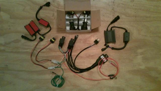
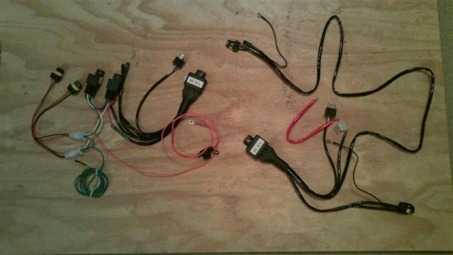
  1. I made an extra "key" out of a small piece of sheetmetal (part of an old CPU power supply actually). I found that when turning the worm drive it would bend this piece...you can see in the picture of the CCT disassembled that it is twisted. I then used the small flatblade screwdriver that I ground the sides down and it worked much better. I think you have the right CCT part #, I don't have my other in front of me....there is only one choice available now I think.
  2. Ok, I am not a writer. I don't have the witty banter abilities of great technical writers who pull you into their project no matter the subject. Instead I am a typical desk jockey who rides VFR and fixes stuff if he can. Before I get into the "easy" way to change the CCT, let me point out that I did not come up with the process on my own. I borrowed bits and pieces from lots of people. The best replacement guide can be found here, CCT change by Rad, where it is done "by the book". In the resulting discussion it was revealed that removing the Throttle Bodies and so forth was a waste of time, as the CCT can be removed without it. As a second note, I did not change the rear CCT, and I don't imagine I know or could discover any easier way...it seems simple enough already. See the link above to find how to change that CCT if needed. As a third note (I like notes), I don't believe the CCTs EVER go bad...I think they make noise when the spring loses a bit of tension...more to come on that later (see how I "hook" you...just like the creative writing class said!) So on to CCT removal and replacement (this order works best I have found)...Anyway, I didn't have music playing, I don't drink beer, and I barely remembered to take pictures....so bear with me. Finding the CCT was the first chore. It is located on the right side, kinda behind and back of the R/R. To find it you need to remove: Right Fairing 8 allen screws 1 blind rivet Slider (if applicable) Seat Just use the key, and remove Tank two 8mm head bolts, use 1/4" driver Restraint Cable Two 10mm head bolts at back of tank Air Box Top Hose from top screws around perimeter Air Box Bottom Velocity Stacks, Phillips Head Bolts Sensor connector on bottom Vacuum line going in front of box Small connections at the back When moved, the airbox looks like this: Note the airbox was just rotated away from the CCT. Tank was also rotated the same way and laid across the seat rails. You can see the CCT at the very bottom, just right of center. Now you are almost there....just need to remove those cooling hoses to make it stupidly easy to reach the CCT. Remove the one pointing out first, and connect a short section(2-3 feet) of 1/4" or similar hose (I didn't measure it, just some I had around, but 1/4" should be about right). Route this into a drain pan or later you get this: next remove the second hose....this is what makes the first connection take a bit of a leak not much fluid is lost...a bit more than is pictured here: Don't leave this for the dog/cats to drink, unless you don't like them much.... Now it's time to remove that CCT! Simply use your 8mm socket on extension, and take the center bolt out: This is where the "key" goes in. The keys job is to stop the CCT from extending when you remove it from the engine. Keeping it from extending makes it less likely that you knock a bit off into the motor, and also makes it easier for the CCT to clear the various bits above it. If you are really ambitious you could actually rotate the CCT to shorten it and make it even easier...but that would be over kill. After loosing both mounting bolts, and removing them, the CCT just slides right out: Here is where I have to admit I have a problem. I enjoy seeing how things work. I managed to restrain myself from taking apart my new CCT to see how it works, but the old one was just there....so I had to do it. Initially I planned to try the Reddog idea of tightening the spring....but I screwed up my spring after I removed it, so that was nixxed. Here is a nice picture of my CCT doing it's best Humpty Dumpty impression: you can see where the spring is messed up....yours won't look like that (don't take it apart to see tho). Let me describe the parts, so hopefully this makes more sense to those who want to know. Those who don't want to know can skip to anther thread or something... Clockwise starting from the left you have: CCT Gasket CCT body, with circlip just slid back key Sping(in the middle) bushing/sleeve Worm Drive Shaft with puck on end The sleeve/bushing goes around the worm drive, and over the shaft below the locking tab. The locking tab doesn't come off the shaft (without removing far too much). The way the CCT works is this: The spring is coiled around the shaft, with one end going into the slot at the bottom of the worm drive, and the other end into a slit at the top of the CCT body. As the worm drive is rotated clockwise, the spring winds up....and if allowed the worm drive will rotate counter clockwise to release tension. The worm drive can only rotate 4 times before the Shaft reaches its stopper. I believe the reason you begin to hear CCT noise is that the spring is able to unwind with a bit of Cam Chain stretch, and thus the spring is not as tight as it was originally. This loosness allows a bit more play that normal, and oscillations begin. Whether different oils help or not I don't even want to discuss. If you wish to attempt to modify your CCT to save some cash, here is how you do it: Holding the CCT in such a way that your finger restrains the shaft from advancing, remove the "key". Using a small (probably modified for the purpose) screwdriver, rotate the wormdrive from the access hole clockwise until it stops. Counts the revolutions. It will stop with the shaft all the way compressed. Now reinsert the key, and while still holding the shaft, slide the circlip down so it no longer restrains the locking tab. slide the locking tab carefully up the shaft out of the grooves, noting 2 grooves are wider than the other 2. Then very carefully rotate the shaft counter-clockwise 1-2 times as many revolutions as it took to compress it initially. (this figure is a guess, your results may very, I make no guarantees..written, expressed or otherwise, not available in all locations, subject to rule changes etc). After rotating the shaft counter-clockwise, slide the locking tab back down, and replace the circlip. Re-insert the screwdriver and rotate the gear clockwise to compress the shaft once more. Now you can reinstall the CCT and see if you saved $100. Reinstalling the CCT is the reverse of removal (I hate it when manuals state that, but it's true. Just check and make sure all connections are replaced or you may not like the results...I didn't. That is the connector I forgot. The FI light was blinking when I started the bike. I was able to get it back on without removing the air box again using a long thing screwdriver. Speaking of which, here are all the tools I needed to do the job: 1/4" driver handle 1/4" Rachet 1/4" x3" extension 1/4" x 6" extension 1/4"x1/4" socket for hose clamp 1/4"x8mm socket for CCT bolts and tank bolts Phillips Screw Driver 3/8" Rachet 3/8"x10mm socket 3/8" x 6" extension Needed this time, but not always required: Long Needle Nose pliars Extra Long thin screwdriver Telescoping Magnetic pickup tool Some pictures were not included, you can see them all here: http://www.wiremybike.com/Slideshows/CCT%20Change/
  3. Ok, I am not a writer. I don't have the witty banter abilities of great technical writers who pull you into their project no matter the subject. Instead I am a typical desk jockey who rides VFR and fixes stuff if he can. Before I get into the "easy" way to change the CCT, let me point out that I did not come up with the process on my own. I borrowed bits and pieces from lots of people. The best replacement guide can be found here, CCT change by Rad, where it is done "by the book". In the resulting discussion it was revealed that removing the Throttle Bodies and so forth was a waste of time, as the CCT can be removed without it. As a second note, I did not change the rear CCT, and I don't imagine I know or could discover any easier way...it seems simple enough already. See the link above to find how to change that CCT if needed. As a third note (I like notes), I don't believe the CCTs EVER go bad...I think they make noise when the spring loses a bit of tension...more to come on that later (see how I "hook" you...just like the creative writing class said!) So on to CCT removal and replacement (this order works best I have found)...Anyway, I didn't have music playing, I don't drink beer, and I barely remembered to take pictures....so bear with me. Finding the CCT was the first chore. It is located on the right side, kinda behind and back of the R/R. To find it you need to remove: Right Fairing 8 allen screws 1 blind rivet Slider (if applicable) Seat Just use the key, and remove Tank two 8mm head bolts, use 1/4" driver Restraint Cable Two 10mm head bolts at back of tank Air Box Top Hose from top screws around perimeter Air Box Bottom Velocity Stacks, Phillips Head Bolts Sensor connector on bottom Vacuum line going in front of box Small connections at the back When moved, the airbox looks like this: Note the airbox was just rotated away from the CCT. Tank was also rotated the same way and laid across the seat rails. You can see the CCT at the very bottom, just right of center. Now you are almost there....just need to remove those cooling hoses to make it stupidly easy to reach the CCT. Remove the one pointing out first, and connect a short section(2-3 feet) of 1/4" or similar hose (I didn't measure it, just some I had around, but 1/4" should be about right). Route this into a drain pan or later you get this: next remove the second hose....this is what makes the first connection take a bit of a leak not much fluid is lost...a bit more than is pictured here: Don't leave this for the dog/cats to drink, unless you don't like them much.... Now it's time to remove that CCT! Simply use your 8mm socket on extension, and take the center bolt out: This is where the "key" goes in. The keys job is to stop the CCT from extending when you remove it from the engine. Keeping it from extending makes it less likely that you knock a bit off into the motor, and also makes it easier for the CCT to clear the various bits above it. If you are really ambitious you could actually rotate the CCT to shorten it and make it even easier...but that would be over kill. After loosing both mounting bolts, and removing them, the CCT just slides right out: Here is where I have to admit I have a problem. I enjoy seeing how things work. I managed to restrain myself from taking apart my new CCT to see how it works, but the old one was just there....so I had to do it. Initially I planned to try the Reddog idea of tightening the spring....but I screwed up my spring after I removed it, so that was nixxed. Here is a nice picture of my CCT doing it's best Humpty Dumpty impression: you can see where the spring is messed up....yours won't look like that (don't take it apart to see tho). Let me describe the parts, so hopefully this makes more sense to those who want to know. Those who don't want to know can skip to anther thread or something... Clockwise starting from the left you have: CCT Gasket CCT body, with circlip just slid back key Sping(in the middle) bushing/sleeve Worm Drive Shaft with puck on end The sleeve/bushing goes around the worm drive, and over the shaft below the locking tab. The locking tab doesn't come off the shaft (without removing far too much). The way the CCT works is this: The spring is coiled around the shaft, with one end going into the slot at the bottom of the worm drive, and the other end into a slit at the top of the CCT body. As the worm drive is rotated clockwise, the spring winds up....and if allowed the worm drive will rotate counter clockwise to release tension. The worm drive can only rotate 4 times before the Shaft reaches its stopper. I believe the reason you begin to hear CCT noise is that the spring is able to unwind with a bit of Cam Chain stretch, and thus the spring is not as tight as it was originally. This loosness allows a bit more play that normal, and oscillations begin. Whether different oils help or not I don't even want to discuss. If you wish to attempt to modify your CCT to save some cash, here is how you do it: Holding the CCT in such a way that your finger restrains the shaft from advancing, remove the "key". Using a small (probably modified for the purpose) screwdriver, rotate the wormdrive from the access hole clockwise until it stops. Counts the revolutions. It will stop with the shaft all the way compressed. Now reinsert the key, and while still holding the shaft, slide the circlip down so it no longer restrains the locking tab. slide the locking tab carefully up the shaft out of the grooves, noting 2 grooves are wider than the other 2. Then very carefully rotate the shaft counter-clockwise 1-2 times as many revolutions as it took to compress it initially. (this figure is a guess, your results may very, I make no guarantees..written, expressed or otherwise, not available in all locations, subject to rule changes etc). After rotating the shaft counter-clockwise, slide the locking tab back down, and replace the circlip. Re-insert the screwdriver and rotate the gear clockwise to compress the shaft once more. Now you can reinstall the CCT and see if you saved $100. Reinstalling the CCT is the reverse of removal (I hate it when manuals state that, but it's true. Just check and make sure all connections are replaced or you may not like the results...I didn't. That is the connector I forgot. The FI light was blinking when I started the bike. I was able to get it back on without removing the air box again using a long thing screwdriver. Speaking of which, here are all the tools I needed to do the job: 1/4" driver handle 1/4" Rachet 1/4" x3" extension 1/4" x 6" extension 1/4"x1/4" socket for hose clamp 1/4"x8mm socket for CCT bolts and tank bolts Phillips Screw Driver 3/8" Rachet 3/8"x10mm socket 3/8" x 6" extension Needed this time, but not always required: Long Needle Nose pliars Extra Long thin screwdriver Telescoping Magnetic pickup tool Some pictures were not included, you can see them all here: http://www.wiremybike.com/Slideshows/CCT%20Change/
  4. Tightwad

    Busted!

    that sucks! I was hoping to see the video of the actual stop tho...wanted to see how you handled him.
  5. Well, the purpose of the SCR is to transfer high amounts of current to ground...in the case of the SCRs I am testing with each can handle 35 amps I believe. Usually only one or two legs needs to be grounded to reduce the charging voltage. The reason you have to ground them is otherwise the Diode would keep passing the voltage. If you tried to just disconnect the power from the diode you would get problems with arcing and such...too much power to switch on and off, so you ground the excess. As long as your ground plane is good, and you have a way to bleed of extra heat, you don't have an issue. Smaller charging systems also have less of an issue as their initial output isn't that great.
  6. Does Al Lambs stock the the valve buckets or shims or whatever it takes? I am thinking of checking mine, but it is my commuter and I can't leave it down for weeks waiting for parts.
  7. If you have some to share that would be great. The only way to limit the charging is to divert the voltage from the Rectifiers to somewhere, and Ground is where they go. If they didn't go to Ground the Rectifier would just keep on charging.
  8. By shunting the current straight to ground with the SCR's aren't you are going to put a load on the engine at high RPM? I honestly don't see this as a much better system then the current design. Honda's wiring and components suck. The placement of them on the chassis are poorly thought out and executed. Electrically the original design functions correctly. By design RR's make more heat when there is more load placed on them. Anything that makes as much heat as a rectifier needs to be physically designed to handle it, Honda didn't do that. They only designed it to handle a correctly functioning charging system. As soon as loads increase beyond a properly functioning system (weak battery or bad connections/grounds) it overloads/overheats and fails. Honda got cheap and lowered there quality to the point we have problems with them. The eighties bikes had better designed RR's and the bikes of the time had a lower load on there electrical systems that they had to power. If you look at the eighties RR's they are fully encased in metal with built in heat sinks then in the nineties they came out with the metal box that was potted with epoxy. Now they have gone back to the eighties design. This IS the current method Honda (and most everyone) uses. There is little other choice actually, because we don't have a "field" circuit that can be activated/deactivated like a car does.
  9. Better yet, relocate it to some location where it gets a continuous stream of 'fresh' air. Doesn't even have to be cool air, as long as it can transport the heat away from the RR. Ducati acts a lot quicker than Honda as there is a recall for the 1098 & 848 that has charging problems due to an overheating regulator/rectifier. The RR is located close to the exhaust and the fix is that the RR will be replaced and a heat shield put betwen the RR and the exhaust pipe. Moving the R/R is not easy, although it can be done. The 6th gens don't have near the heat issue that previous models had. 3rd and 4th gen were the worst, because the surface area of the R/R was so small. As an update, I tested one circuit and didn't have the results I wanted. I did find that they SCR's heated up nice and fast, to well over 130 degrees (they are on a computer headsink, so not ideal). I am hoping to have more time over the Christmas break to play with it, and to try an alternate circuit.
  10. Mobil 1 10/30, or whatever was recommended. This is the first they have made noise, started at the 25K mark or so, just got a BUNCH noisier (to the point of concerning me) on Friday. I figured the gasket was reusable, but for $2.25 I wasn't doing it again. Same with the bolts....I can always use more bolts, so the $3.25 spent there is an investment. I figure i will look at my old ones and see what I can learn....must be something.
  11. Order my parts from Dave Lusk as well: Tensioner - 14520-MCW-013 - 54.28 x 2 = $108.56 Gasket - 14523-MCW-003 - 2.25 x 2 = $4.5 Cups - 14524-MBB-000 - 4.00 x 2 = $8 Bolts - 90004_GHB-600 - 1.75 x 4 = $7 Shipping = $6.50 Grand Total = $133.56 (no the math doesn't work, he cut $1 out somewhere....) Said it would be 7-8 business days to ship, which isn't any worse than anywhere else. Very nice guy, and the tensioner savings was tremendous. The other parts weren't that discounted, but no complaints from me. Now I will try the "no TB removal" installation technique, during which I will most likely employ the essentials from the "Sailor Vocabulary and You" course I have been auditing.
  12. I'm pretty sure you have it backwards. The resistor is across the heater circuit to fool the ecu into thinking the o2 plug is still present, in order to prevent the FI light from going on. The other two wires are the voltage measurement circuit. These wires are not plugged in to anything, so I'm guessing the ecu will measure a steady 0 volts. At least this is what I gleaned by looking at the wiring diagram in the shop manual. You are right, as I read through the thread better. I thought the mod made the bike think it was in the right range, instead it keeps it in closed loop mode. The resistors will get warm if you don't use a 1/2 watt resistor or so.
  13. It's my understanding that the resistors are there to simulate the presence of the heater element in the o2 sensor (the two white wires on the sensor connector), so I suppose that's why they get warm. The other two pins are left unconnected, and present a reading of 0 volts (full lean) to the ecu, causing the ecu to attempt to compensate by going full rich. The power commander then makes the final adjustment to the injectors. Obligatory caveat: I'm not an EE. I just google alot. This is not at ALL what I understood the resistors to do. The resistor is providing a voltage signal that tells the computer the O2 reading is perfect. This takes the variability out of the air/fuel ratio. The heater circuit is not touched, it is just there to get the O2 sensor up to speed faster anyway.
  14. My GF will be glad to hear that! See's gonna get me one for Xmas! :biggrin: See if you can get it set up to be shipped out in time. :blink: Depends how late Christmas comes at your house....if people had 3 weeks to opt in that wouldn't leave enough time to ship
  15. I have contacted Pro Oiler about a group buy...figured it might get us a deal and shipping would be less painful for the US folks at least, and possibly the Canadians as well. I will start a thread in Bargain Finder when I get the details about price tiers etc.
  16. Alternators in cars can actually control the Electromagnetic field to stop the charging altogether. This isn't possible on a bike without increased space needed.
  17. For those who wish to see the Schematic(s) used, I am including them below. I am testing two different kinds, to see what I think. The first is easily adjustable (before sealing up of course), and the second is adjusted using the correct resistor values. I have bench tested the first method(prior to Stator hookup, just checking that the SCRs trip as expected), more pictures to come later. I found I needed a higher resistance potentiometer than was specified, and I will be researching why that is. As a disclaimer, I did not create these circuits.
  18. I can just imagine suggesting this as a serious course of action. "Using a medium sewing needle, carefully pierce the seal on the counter shaft, at the 2:00 position. The correct angle is 54 degrees, and should be done with a red-hot needle (white hot could be damaging)" I have always said my Jeeps oil is self changing.....7 years ago I actually took the oil plug out.
  19. Fixing the Stator connector to a more positive locking type is an ideal fix. If someone had a connector that let you bolt ring terminals together that would allow for the most surface area, and prevent the arcing that occurs and generates heat.
  20. If the purpose of the R/R is to convert excess electricity to heat and heat destroys the R/R, why not separate the vulnerable components from the heat by having a remote electric radiator separate from the R/R electrical components? The real key is to make it so the R/R doesn't need to bleed off the excess, thus the componets that typically fail (SCRs) won't even have the chance. This was a very interesting read: forgot to give credit to the author: http://groups.google.com/group/rec.motorcy...6f1bb8cbbdacae2
  21. Only for fun, and pre-Patriot act of course...although "Improved" would be pushing it...
  22. I now have 98% of the parts needed to make my own R/R, and test some theories. More to come on this topic as I actually do something. On a side note, I now know how to make an adjustable low amperage voltage regulator, which I needed to correctly set the on-off point of the R/R. I also obtained some high-amp parts that will hopefully not fry something.
  23. I was actually wondering this same thing, as the force required to maintain belt tension ("overhung" or "radial" load) would be much different than that experienced with a chain.
  24. Nice read, sounds like a fun trip! Your wife is awesome for bailing you out (again)! Tell her I said hi.
×
×
  • Create New...

Important Information

By using this site, you agree to our Privacy Policy.