WGREGT
-
Posts
802 -
Joined
-
Last visited
-
Days Won
8
Content Type
Forums
Profiles
Gallery
Blogs
Downloads
Events
Everything posted by WGREGT
-
Wow. We are moving fast. Since my last posting above, we have: -made 3 rounds of CAD drawings with improvements each time -sourced and bought 4 different kids of bolts/nuts, none of which have the conical shape on the bottom -added the 3 "bumps" on the top of the base in the same size/position as seem on the GSXR OEM base. This will help it lock into the steps. -drilled the mount hole clear thru to allow for the OEM belleville washers to be used, which allow it to hold tension on the mirror -inset the jam nut and washers into the base, thus allowing it to be hidden from view -kept the wire exit hole as before, within the base footprint, to allow the drill hole to be hidden by the base when installed I just spoke to he machinist/designer, and I think his plan is to start cutting samples monday am. More when I know it.
-
OK. Here's where I am on this project. After MUCH time waiting and discussion, the place that was initially going to cut these for me has dropped out. Why? Too many other projects on their plate. I patiently waited, hoping it would be resolved, but it's not gonna happen. Just today, I handed the project off to ANOTHER person/shop. We met for a good 2 hours on it, and it comes at a good time: due to concerns from those who have these already, I'm doing a slight/better redesign. Here's the changes: -Taking cues for the OEM Suzuki GSXR mirrors, we both thought machining the 3 small "bumps" on the new base where it contacts the mirror would be a good thing. These detents help to keep the mirror tight to the base and in one position, yet still allow it to be folded in by harder pressure if needed. -But, since the other half of that idea that Suzuki used in their mirrors involves the belleville washers (qty. 4) as well as a flat washer, we thought we'd incorporate those as well. But....where to do that? Where would you put the washers in the current design? The only way is to change the capured threaded hole (where the bolt goes) to a complete thru hole, and put the washers on the bottom, and use a bolt UPWARDS from the bottom of the base to hold those washers, as well as the mirror arm, and put a small nut (and maybe washer) on the other end, under the removable black plastic cap/cover on the mirror. -This bolt COULD be the threaded rod we talked about ealier with the pre-cut slot running the entire length of the rod. I have to go check @ the hardware store this weekend. The slot still needs to be wide enough to pass the wire out of the side of the rod and to come out of the existing hole in the base as before. -We'd liike for the 5 washers, as well as the bolt head, to be hidden/inset within the base so you could not see any of it from the outside, of course. So, since we have to take material away in order to inset these washers and bolt head, that weakens the base. So the plan is to add some back by building up the base a bit more, yet still keeping the same footprint. I'd especially like to know those of you who had the original base and had it split on you (N8sVFR?)...where did it split? Do you have fotos of the pieces? So, that's where I am now. I know that some of you will be a bit dejected to hear that these are not ready to go, and all I can say is: Sorry about that. I am still actively working on it. I hope to have new drawings within the week, and I'll post some screen grabs here when I get them. If you guys have thoughts/suggestion/issues/problems that popped up as you were reading this, let me know. You may think of something we have not (though my new machinist's resume does boast of making designing small rotational multi-directional units that are used on the solar panels on satellites that are right above your head right now.) Love to hear your thoughts. Lastly, I'll add this for those of you who don't know me and that I had not had the pleasure of riding with yet: My personal slogan is “My strength lies solely in my tenacity." I will get this done, rest assured. The timetable has been out of my hands for a bit, but I don't quit on stuff. Thanks for listening and understanding. I'll post more when I know it.
-
You find out where these washers were placed originally in the GSXR mirrors?
-
Where'd you get those mounts? Make 'em yourself? Looks like that's a hex-head bolt. Drilled all the way thru AND cut?
-
I should ask... anyone else who has a set of these original GSXR mirror mounts from DBling: ever have any issues with cracking/splitting or even the mirrors flopping forward? Would love to hear about it if so.
-
I'd be interested to find out where they originally were. I'm sure they were not between the mating sets of notches between the end of the mirror and the GSXR base, so....where else would they even make sense and be able to put any pressure on the point of contact?
-
OK. Got it. Let me see if I can source those at the right length so I would not have to cut them at all.
-
OK. Hollow threaded stud sounds good to me if I can find 'em. Let me see about that. Never having used those before, I'm assuming the shaft doesn't spin when putting the nut on the one end...what's holding the other end tight since there isn't a head on it? I think I do remember those flat black washers coming off, and I do remember thinking "Just regular washers...trash 'em."
-
I just went out and looked at all of the parts on my GSXR mirrors after I pulled them apart, and all I have are a couple shiny flat washers. So I'm guessing that ain't the spring washers. I'm guessing spring washers must be thinner washers? Still got yours somewhere? If I can improve them, I gladly will. Just trying to get a handle on it to relay it to the guy doing the work.
-
I understand what you are talking about with the shape of the bolt, but the bolt was chosen b/c 1) the flat head allows ease of drilling for the hole for the wire to pass thru, and 2) it allows room at the top, once inserted and tightened, for the black OEM mirror cap to snap in and cover the hole. I *guess* there are other screws that might work that are flat on the top and not conical on the bottom. I'll go back to the email I originally got fir the CAD drawings and see what else might be on that list, if any. You're calling those detents "spring washers" like they compress or move like a spring? I'm not sure where the spring action is coming from....? Found it just now. Here's the link and the email about picking the bolt he did (third row, third from left): "The top hole that secures the mirror stem to the mount is tapped with 3/8" course thread (16 tpi). You can of course pick a different size if you want/need to. The screws I bought were Philips countersunk , just like in this picture: http://www-mdp.eng.cam.ac.uk/web/library/enginfo/textbooks_dvd_only/DAN/threads/intro/heads.jpg I drilled a hole straight down though the screw to allow the wires to pass through the center of the screw. I also choose a Philips head which allows me to tighten the screws if they ever become loose without having to worry about the wires (just use a regular flat head screwdriver instead of a Philips)." As far as changing the bolt, once I get the finished part in hand I have no problem trying something else that is not countersunk (no conical shape on the bottom) that still allows room to install the cap cover, and yet still tighten the bolt with the wire going thru it if need be.\
-
This your first time here? That's how we do things...we string them out forever, often thru no fault of our own. Gives Kanadiens something to talk about in the off-season from July-May. Yep. I remember the bit about the shrink wrap on the outside of the stalk. But I don't think I ever saw good fotos of the mount itself, or the stalk itself. The ones I'm (still) working on will also need a small 1/8" hole drilled, but it will be UNDER the mount, between the mounting bolts, and unseen. So you can go back to stock when you sell the bastard... I will say that since this thread started I've talked to a few members here who have the mounts from Darth originally, have the GSXR mirrors, and haven't mentioned anything about cracking or the mirrors flopping forward, for what that's worth.
-
I'm not versed on the Ninja 6R mounts. Would love to see some fotos close up. How are they different/similar to the GSXR mounts? Maybe shoot a little Youtube video of them on the bike, showing what you mean about flopping forward?
-
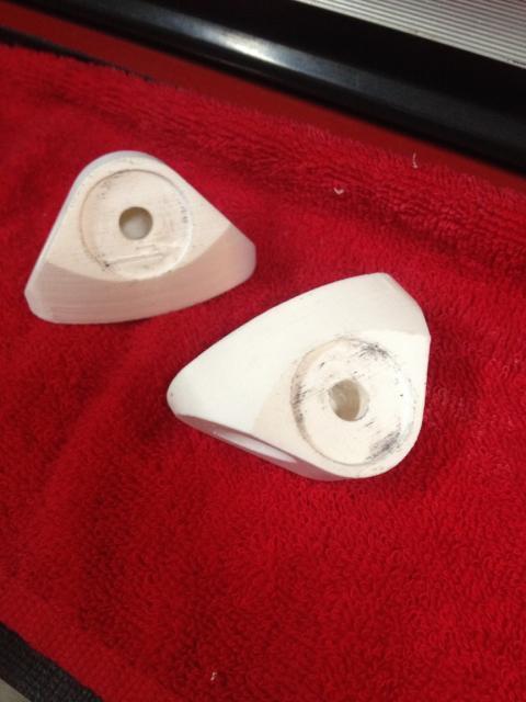
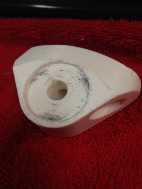
Your comment of "flat head phillips bolt" has thrown me off as well. I thought you said/meant "flat head bolt", which I initially thought meant you had an early version, 'cause the plan now calls for a phillips head bolt. So you'll have to explain that one again. I know the 3 small male bumps on the bottom of the GSXR mirror arm you are talking about. You're suggesting 3 small female indentions in the new base I'm making? Those things are really small on the GSXR arm...not sure they'd make any difference on the base I'm making. You can see the small black marks on the first foto of the ABS mounts on the round detent in one of the fotos...this is where the 3 male bumps touch/rub on the mount. I actually like the fact that the GSXR mirrors will fold in/swivel on the base to fold them in (while lane splitting out here in CA.) I think if we had 3 small corresponding female indentions to match up it would prevent the ability to fold them in. As far as the bolt itself, I'm not sure the head on the bolt makes any difference on the too-much-tightening thing. The flat head was chosen so it can be easily drilled for the wire to pass thru, and it sits flat in the mirror housing when tight, allowing you to install the black Suzuki OEM cover cap. And you say the pressure is outward instead of downward? Huh? It's all in line with the bolt. You'll have to fill me in on that too. Another thing I just thought about: What if someone wanted signal mirrors that were not GSXR mirrors?
-
Sure, I'd love to see some photos. When I got the CAD drawings and info from Darth, he gave me suggestions on just about everything, which was helpful. When I got them, he spec'd the bolt as a phillips countersunk, 3/8” coarse, 16 TPI screw. So maybe he changed it after your production run? Also, the design I have has circular detents for the mirrors (shown.) Did your design have them? PS these ABS samples don't show the threads cut into the mirror mount hole in the middle of the detent. Hard to do that in ABS.

-
Just got word: we are on the table as I type. Not sure how long they take per piece. I've asked. I'll post up when they are done.
-
I heard back just now about the mounts. We are still in line to have them done but real paying customers have priority. Sheesh! Hopefully this week. You'll know more the second that I do...
-
My guy was on vacation all last week. I hope to hear something today along the lines of "Come pick them up!" I'll let you know when I know something.
-
Never too early to ask for updates. As of 8/12, we were in line to have the AL blocks cuts. The guy I'm dealing with is on vacation this week, but he connected me to another guy who will run the machine in his absence. Let me check in with him right now.
-
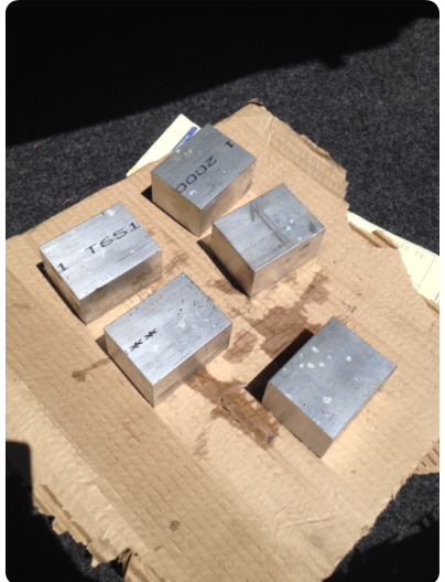
Dropped off the AL blocks just now. Might get lucky and get them back this week, then the tap & die for the threaded portion, then on to the anodizing, buying and drilling the screw, and then we should have viable finished samples to show. More when I know it.
-
Good Lord, Mate. Each one of those blocks will make 1 mount. I don't think there's gonna be any reselling of scrap, but I will ask. I have not taken into account what the machinist wants to do the work, the anodizing, or the box/shipping, simply b/c I don't know those things yet.
-
Blocks are cut and ready to go once the soft samples are done...
-
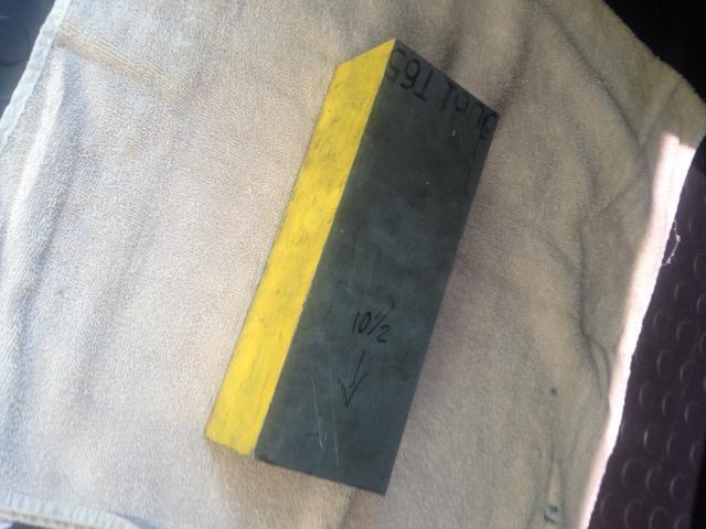
We're running a round of samples this week made from a soft bonding-type board-like material. According to the guy running the CAD machine, it's just to run the programmed tool paths on material softer than aluminum for the first run. Sometimes as the cutter head swings about on successive passes, it may nick an edge or something. The enclosures surrounding the mills are not bullet proof, and sometimes they are shattered by flying debris, which I may be asked to pay for. So this allows them to test everything first and prevent that. More when I know it...
-
That one block shown in the foto was $40. Not sure how many I'll get out of it though. I'm told the machine needs a bit of waste to hold the block in order to cut them.
-
AL block for samples dropped off. Got prices on anodizing them afterwards as well. PS: The Delrin is way expensive. Like $96 USD for a block big enough to make 2 sets from. So, right now I'm gonna make the samples in the AL, anodize them in black, and see how the pricing works out to see if making them in plastic gets them any cheaper, or if there's even a need to try the plastic route. Should have samples in hand shortly, then 2-3 days to get them anodized. More when I know it.
-
AL and Delrin blocks ordered today for test runs. We'll make 2 sets in AL, and 2 sets in blk Delrin. I'll let you know when it's here.