
HispanicSlammer
-
Posts
6,987 -
Joined
-
Last visited
-
Days Won
69
Content Type
Forums
Profiles
Gallery
Blogs
Downloads
Events
Posts posted by HispanicSlammer
-
-
I just do a search in the gallery for the word 'featured' as comments
-
What ever you dont get suckered into riding faster then you want to. 2 hours in the saddle is NOT MUCH, thats a short hop for me.
When the wagon train gets to Colorado guys, let me drop in as well, we might have to go AROUND the mountains till they thaw out.
-
Mine failed over 2 years ago and cost me $2000 in repair cost, I wish the recall came out earlier.
I just got my recall notice, in it there is a provision and form for owners who have had theirs repaired to get reimbursed. Check that out. Of course my notice came from American Honda, so you will have to get the notice and reimbursement form perhaps from the dealer who sold you the bike.
-
Wait until you start using "gimp" https://www.gimp.org/
I downloaded it and am trying it out, its very alien to me, working on learning it now.
-
whiteknuckles Thank You, Your donation of Not Available will go toward Maintenance and Upkeep of vfrdiscussion.com
-
Well I have had nothing but problems with my desktop computer, I had all the pictures set up to make a calendar this year and then the raid drive on my computer failed, I tried to repair it several times but it just kept corrupting so I had to reformat the hard drive array. I lost all the pictures. I wasnt expecting to do a calendar but Dutchinterceptor said he had too much to do and could not do it this year. I took over and now I have to start all over again. If there is really no interest I wont waste time on it. I couldn't even reinstall windows cause my cd disk is all messed up and wont copy key files. I ended up installing Linux and I really like that. Now I have to download an image editor and learn how to use it first. Its just been a monumental messed up project.
The Good thing is the vfrd server is running very well, no issues, there is a new version out for the software I need to install since support for this one is evaporating but there are key pieces missing yet, namely the module I use for the classified ads, there is no update for that yet so that is the hold up there. I am looking for alternatives, I dont want to put the classifieds into the forum since that was a huge problem for me when I tried that a number of years ago.
-
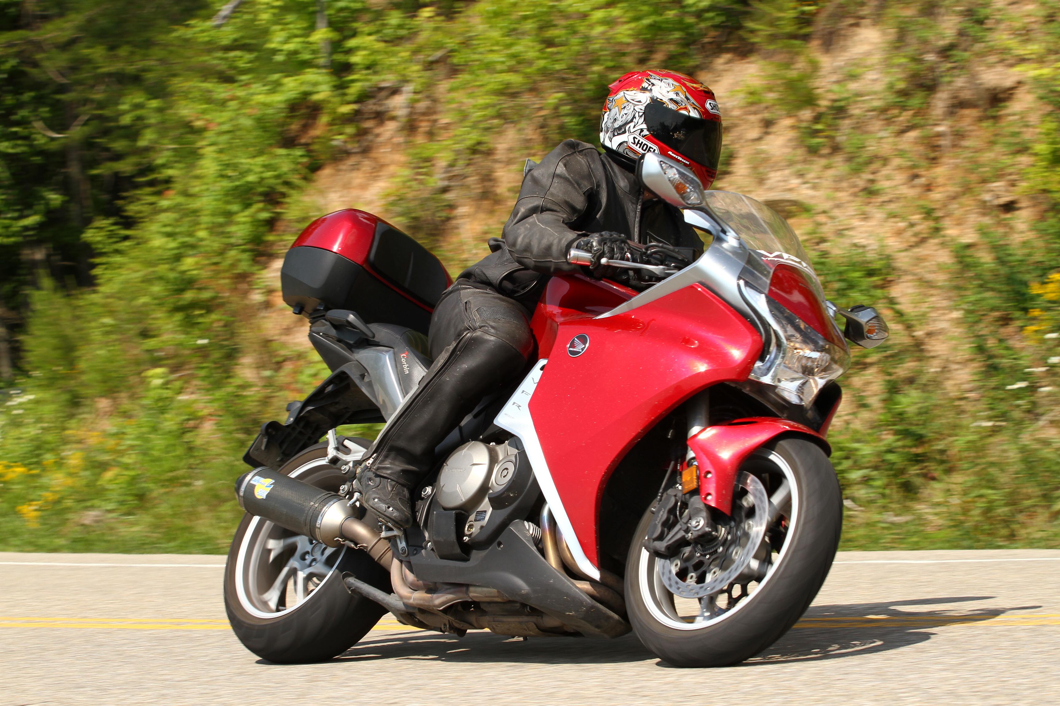
looks like a 6th gen swingarm. sounds like a vfr thats for sure
-
I simply cannot commit at this time my employer is in the process of a sale, dont know whats going on. I want to go but if I get laid off its not gonna happen.
-
Jon is in Europe at the home office of his employer, me I am at home in the Springs. Drunk guys should not make plans, the europe thing sounds good but I just cant swing it right now.
-
I hope 2016 is the best ever! Merry Christmas, happy Hannukah, happy new year.
-
I almost have 50k on this bike - I will get the work done but doubt it has an issue, it would have failed by now? She needs some loving care, shock rebuild, new rear brake disc ready to put on, replacing some plastic, new shoes, new tires. I will be ready this summer to ride.
-
VIN: JH2SC6317AK000775
- YEAR: 2010
- CATEGORY: MOTORCYCLES
- SUB-CATEGORY: SPORT
- MODEL: VFR1200F
-
NUMBER OF OPEN RECALLS: 1
LAST UPDATED: DEC 14, 2015
NHTSA RECALL NUMBER: TBD CAMPAIGN DESCRIPTION: 10-13 VFR12 PROPELLER SHAFT MFR CAMPAIGN ID: JW2 RECALL DATE: 12/04/2015 RECALL STATUS: Recall INCOMPLETESUMMARY:AMERICAN HONDA MOTOR CO., INC. (HONDA) IS RECALLING CERTAIN MODEL YEAR 2010 AND 2012-2013 VFR1200F/FD MOTORCYCLES. THE DRIVESHAFT UNIVERSAL JOINT BEARING MAY NOT HAVE BEEN PROPERLY ASSEMBLED AND, EVEN IF PROPERLY ASSEMBLED, MAY NOT HAVE SPECIFIED DURABILITY AS THE RESULT OF MANUFACTURING ERRORS.
SAFETY RISK:IF THE UNIVERSAL JOINT SEPARATES, DRIVE FORCE WILL BE LOST; IF THE UNIVERSAL JOINT BREAKS, IT IS POSSIBLE IT MAY INTERFERE WITH THE SWING ARM AND LOCK THE REAR WHEEL WHILE RIDING. EITHER OUTCOME INCREASES THE RISK OF A CRASH.
REMEDY:HONDA WILL NOTIFY OWNERS. AND DEALERS WILL REPLACE THE DRIVESHAFT, FREE OF CHARGE. WHILE AMERICAN HONDA EXPECTS TO RECEIVE THE FIRST SHIPMENTS OF THE REMEDY PARTS IN LATE 2015 TO EARLY 2016, CUSTOMERS WHO ARE CONCERNED ABOUT THE POTENTIAL OF EXPERIENCING SYMPTOMS OF THE DEFECT BEFORE THE REMEDY PARTS ARE AVAILABLE CAN BRING THEIR VEHICLE TO A HONDA MOTORCYCLE DEALERSHIP FOR INSPECTION. IF THE DRIVESHAFT FAILS THE INSPECTION, THE DRIVESHAFT WILL BE REPLACED WITH A NEW PRE-COUNTERMEASURE PART, FREE OF CHARGE; THE CUSTOMER WILL BE ASKED TO RETURN TO HAVE THE DRIVESHAFT REPLACED WITH A REMEDY PART ONCE PARTS ARE AVAILABLE. ONCE PARTS ARE AVAILABLE, HONDA DEALERS WILL REPLACE THE DRIVESHAFT ON ALL AFFECTED VEHICLES WITH A REMEDY PART, FREE OF CHARGE.
-
I was part of the Kansas meet and I remember riding past that place, did not get a sample though but I did get a good taste of Kansas mud pie! In my hair, my boots, my suit, everywhere!
-
15% more fuel is a large increase. Sooty smoke indicates a rich condition. May want to check out a different map.
-
Hmmmmmmmmmmmmmmmmm I had a really good time in Nelson last time I went.
-
I do all my own work, I found 3 of my shim under bucket valves where out of spec, I had some tools that are not usually found in a tool box that I ended up using. To pull the bow loose, the vfr1200 uses a spring loaded bow to tension the cam chain rather then a piston design, I used the spring removal tool I got for my leo vince exhaust, which looks like a miniature wire clothes hanger, grabbed the tension hole and pulled on it till the bow was released and the cam chain was loose. Then I used another tool to secure the bow in place - a steel basketball inflation needle which fit perfectly in the slot and held the bow in place. A few small skinny wrenches to get the cam gear off was needed since there is little room to work, it took some coaxing to get the cam shaft off to get to the shims. Also I needed a long screw driver about a foot long to get to the clamps that hold rubber intake flanges between the head and the throttle body. Also a correctly sized spark plug wrench. Torque wrenches to tighten all the bolts back to spec when assembling the cam mechanism. I spent about 4 hours on the job, I could do it faster but I take my time and do it right.
I just unhooked the hoses and wires from the tank and let it swing back as far as it would go, no leaking, it was well out of the way, the airbox has about 20 or so screws to remove its time consuming and a few wires on the temp sensor and map sensor, a few things in the way, the throttle bodies I removed the wire harness at the connectors, and took off the throttle cables at the TP cam. I left the fuel rail intact. took it off and cleaned it all up with carb cleaner It was filthy, cleaned my airfilter too. I had to go buy 3 shims from the dealer, I adjusted all the exhaust valves too they are all rocker valves and very easy to adjust. You have to remove the rocker arms to get the cam shaft off that that was tricky, they dont want to go back in easy, washers get out of position.
I did not remove the radiator I did all the work inside the frame, and its very tight fit. I think I am good for another 2 years - I beleive I put more miles on my bike then most 1200 owners I am almost at 50k now. As long as you are doing all that work its worth it to replace the spark plugs since thats almost the same amount of work as a basic valve check.
-
Watched the video got going pretty good there. Nice rythm in the tight stuff.
-
Some crashes, related to forced moves from server to server, lost some photos in the moves that are unrecoverable. But the vast majority of broken links are hotlinked from outside hosts of which I have no control over, suggest contacting the poster if you want the photos, its a forum its not meant to be preserved forever, just a bunch of motorcycle pictures and post, its not the Magna Carta.
-
Good review
Poor review
-
what are your impressions, mileage compared to other tires you have tried, its hard to compare mileage rider to rider but with the same rider tire wear is it better or worst? Read good things so far, a bit pricy but I did not like the milage on the Pilot road 4

-
-
The important question is...
Will Pedrosa be the man to beat next year? I think next year may be his best chance for a championship.
NO this is Pedrosas MO he always comes on strong late in the season when its too late, mark my words. He will struggle next season again at the start of it.
Anybody else see the "personal matter" Rossi was speaking of in the interview that MM was angry about? Maybe the lead up to all this in the first place, MM brings his crew to VR's place to set up his flat track bike on a supposed 'fun weekend' and pisses everybody off, hes a little shit alright.
-
Why isn't anybody talking about what happened before the crash?
I guess I am one of the few that sides with Rossi. If you look at what race direction said then you can see that Marquez was in fact trying to deliberately slow the pace, just like Rossi accused him of doing at Philip Island.
"Despite what Marquez said, we think he was deliberately trying to affect the pace of Valentino." -MotoGP Race Director Mike Webb
"It's my opinion on the way he was riding, the lap time, my perception is that as many riders do he (Marquez) was trying to change the race." -MotoGP Race Director Mike Webb
On top of that I personally think Marquez was deliberately trying to create contact scenarios. Of course Rossi didn't want to crash because he had a championship at stake.
In regards to the incident, I believe Rossi obviously had the line and did in fact choose to run Marquez wide and slow him down enough to try to get away from him. I believe his three looks towards Marquez was to make sure he avoided contact while trying to run him wide while at the same time saying "stop doing what you are doing". At that point I believe Marquez CLEARLY ACCELERATED AND LEANED INTO ROSSI (see clip below) setting up contact for sure this time, trying to make him crash, but caused his own crash (Marquez helmet to Rossi's knee and Rossi's knee reaction).
WATCH THIS CLIP! Pay attention to the :17 second mark.
I am sure Rossi regrets running him wide.
Not sure Marquez regrets his part in it.
that angle shows marquez initiated contact not rossi wow...he definitely speeded up and hit him first with his helmet. The kick was just a reflex
-
I have been rooting for Rossi all season, not a Marquez fan and not a Lorenzo fan either. However I think they should have black flagged his ass for that stunt! I can see he was upset with the constant harassment when Mark was clearly faster, but that was a really unsporting move. It really soured me on a great season, I will still watch the last race but its pretty much over now. Cant say I did not expect that from him, hes got the killer instinct and its served him well, just seems he was on the wrong side of the fence on this one, hes had some famous battles/feuds with other riders and always the other blinked..not this time. No 10th for him this year and who knows sponsors might pull out of the Yamaha camp for that move.

Vfrd Donation From - Whiteknuckles
in Site Comments, Help, & Support
Posted