tok tokkie
-
Posts
201 -
Joined
-
Last visited
Content Type
Forums
Profiles
Gallery
Blogs
Downloads
Events
Everything posted by tok tokkie
-
Header pipes & 2 big ones inside each side of the can are 38 OD. Three little ones are 22OD. If you mean the perforation holes in the pipes; 5mm I really don't think there is much power difference but the idle speed went up from 1200 to 1500 initially.
-
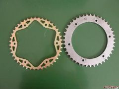
border='0' alt='user posted image' /> Mark 2 with baffles. .. border='0' alt='user posted image' /> Gas Flow Options I have made the new design. I have ended up using gas flow path shown in lowest sketch & am entirely happy with it - not too noisy at all. I have also plugged the cross-talk port & prefer the more v-twin less stinky I4 sound. Riedwaan, the welder, has taken a fabulously paying job on oil rigs in Nigeria & will be away for 30 days so I wont be making any more. (I just need to polish the one for VolatileVFR & it is done). Drawings are available to anyone who wants them.
-
I can send you the plot file for the components if you decide to proceed.
-
When were you wrong? I read your hypothesis that Honda have the correct RELATIONSHIP of spring stiffness front & rear. If you change one then you should change the other to maintain the original relationship. This seems to be what you have just done (+-5%). I also remember you advising specific spring rates at some stage but the thing that stuck in my memory was your relationaship post.
-
Ok. I would be happy to have this thing spread around. My intention is to make drawings for a muffler with 3 chambers each side similar to the one shown in the link I gave to 'HowStuffWorks' near the start of this thread (it will not have the resonator chamber). The other change is it will have 3@22mm tubes between the first & third chambers (not the ports shown in 'HowStuffWorks). Also, it is not necessary to angle the center dividing wall as the muffler can fit in slightly closer to the headers coming down from the rear cylinders. I will also fit a heat shield to protect the suspension dog-bone bearings (getting hot with current set-up). With the removable inlet & outlet tubes I believe we will be able to tailor the noise volume as we choose by adding holes to these tubes in the first & third chambers (both tubes need to have holes in the second chamber if there is to be any gas transfer there). You can even cut the tubes out completely if you wish. I will take the drawings to a couple of laser cutting places to get quotes for all the bits. Riedwaan wants about $80 for bending, welding & polishing. I will charge cost of materials + 10%. I had headers airmailed to me by Trace which cost $53 so I expect it will be similar to that. I will make up my one & check it out before assembling the rest (possibly leave out 1 or more of the 22 tubes). I will supply with 2 extra internal tubes with flanges so you can experiment with different sounds. Please be aware that you will have to cut your headers just after the 2:1 join, fit in the stub tubes I will supply & weld the stubs to the headers & flange. You must remove the ECU & R/R from the bike before welding and disconnect both leads from the battery. WarriorRacer#13 is wanting to offer an exchange program on headers to fit this muffler. That has not been finalised yet. Magellan is, I think, also wanting to make similar mufflers so they may be available ex the US. I have absolutely no problems with anyone using this idea and offering to make similar mufflers. I see VFRD as a co-operative site where I have received lots of advice & help so I am pleased to be able to make a contribution in the same spirit. Anyone wanting a copy of the drawings (as a plot file) is welcome. I would like some indication of how many are interested so I can get quotes for that number of components & come back with firmer pricing.
-
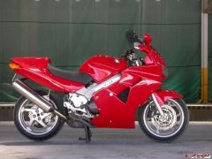
Cool. Ice cool (aluding to the glacier white colour).
-
I went for a decent ride in the mountains today. The dog-bone link just above the new muffler gets very hot. It is not a complete surprise. The cat-con has a heat shield which has a very small air-gap. I will make a heat shield that fits inside the depression on my muffler. That is partly why I made the depression so big. I also considered fitting the heat shield to the dog-bone itself. I would be interestd in knowing if the linkage gets too hot to touch on the standard set-up as I never checked that out before doing this mod.
-
There is no patent or copyright on this thing. Anyone is free to make these things for themselves or others. The more the merrier as far as I am concerned. Ridwaan, who did all the welding for me is a tennant in my building. He has just split from his wife & lives right on the premises. He has also just started as a one-man business doing high quality welding (aluminium cylinder heads etc) but is scratching for work. He is keen to make a batch of these. The problem is making the connection between the existing headers & the new muffler. This requires welding on site. That is going to be a big discouragement I feel as it is not a simple bolt-on (or slip-on) mod.
-
OK. I did Veefer800Canuck's mod. Stub tubes are 150 long. Firstly I cut the inlet stubs down to 75 & welded on 75mm cut off the perforated stubs I had & blanked off the ends. Fitted these back on the inlet side & left all the pot scourers inside. Result: significantly quieter & deepr tone. Then I drilled 5mm holes over the last 85mm of the outlet stubs & blanked off the ends. Fired her up: a bit louder than with just the inlet stubs perforated & blanked off. So I am now running with the inlets perforated & blanked off, the outlets plain pipe with open end & pot scourers in there. This is better. I will read & consider the end hole suggestion & the tapered end suggestion. I don't follow them after a quick read. I am pretty certain I will fabricate another muffler with 3 chambers each side along conventional lines except the stub tubes will still fot in from the outside so i can adjust them. But the bike is usable as it is & there are other things (non biking) that need to be done. Any more advice or suggestions will be much appreciated.
-
You are right on it there. One of the other bikes that inspired me was the KTM RC8 Look Here As for production: Ridwaan is fired up to make these things but lets get it sorted out first.
-
Thanks Rob, that is a great idea. I will try this idea & see what happens.
-
Many thanks for the idea. I have looked around the site. The sound clips are great & just what i would like to replicate. Trouble is i can't find any diagrams of the internal layout of the mufflers. 'Picture' appears on screen but it never resolves into anything more. I would very much like to see what is inside their mufflers.
-
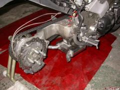
WHAT ALTERNATIVES I CONSIDERED I have admired what Eric Buell has done. He may use a peculiar engine but he works from first principles to are at an optimum solution utelising modern materials. I have particularly liked his low level exhaust and belt drive. I saw this photo of a racing VFR done by BLS: That image also causes this to bomb out when posting. I obviosly don't know how to use the IMG posting button. I BLS's gallery there is a photo I wanted to post here. There is no chain fitted and I assume the up pipe to the muffler is missing but I really liked the look with nothing behind the footpeg on the right side: display as much of the rear wheel without a swing arm as possible. My original thought was to run two mufflers each side under the sump exiting at the front. That would have meant cutting the bottom of the fairing off ? I was prepared for that. I made a plywood template of the fairing so I could measure the space available. There really was very little space. At that stage my thoughts were of a muffler with perforated pipe & fibreglass packing ? the usual straight through exhaust design. I was worried that this would be very noisy because the muffler would be triangular 50x113 on the shorter sides with a 38mm pipe inside there would be very little fibre-glass. I then thought about adding a chamber where the cat-con is so that the gasses expand into it & change direction before getting into the muffler section. Not too difficult as it would simply be cutting the headers apart & re-arranging the components before tiging them together again. It was when I came to look into this idea properly that I saw that there would be quite a lot of space if I removed the center stand. I then removed the headers, hoisted the bike up in the air & measured things. I made a rough mock-up of the muffler out of particle board and checked things out. (To get the center stand off you have to remove the headers ? RH bolt can?t be taken out as it jacks up against the rear cylinder headers). It all seemed to fall into place when I did this. I modeled the thing in my CAD/CAM while I was about it ? lots of back & forth measuring things to get the model right. Working upside down means that what is measured on the right is plotted on the left so it is easy to make mistakes. There are numerous advantages to this lay-out over the previous idea. The oil drain is not covered so oil changes can be done without removing the muffler. The muffler is behind the gearbox so there is no radiant heat onto the underside of the sump. It will be easy to change the internals of the muffler to experiment to get the sound I am hoping for. The exits will be further away from my head so I will not hear the drone of the exhaust so much. Finally I think it will look better especially if the pipes can exit at an angle so I can slash cut them to give an oval exit. I had also thought about joining the front headers in front of the engine with a muffler down the right side exiting near the RH footpeg and joining the rear cylinders to a muffler running under the LH side of the engine exiting toward the front (Bimota had an under engine exhaust like that). This allows for larger mufflers as there are no headers running under the engine. Trouble is the front headers are much shorter than the rear ones so fueling will be different front to rear. Also it would now be a pair of 180 degree parallel twins to each muffler ? not the sound I was looking for.
-
MY QUESTIONS How could I make this thing quieter? Staintune have a ?spud? that fits in the end of their pipe. Can I fit something like that here? What does it look like & how does it work? How about two more walls in the muffler to separate the inlet & outlet sections of each side? I have had a look at How Stuff Works Linky Would it help to make something more like that? Should I make two small straight-through mufflers with perforated pipes & fiberglass (I would suspect they need plenty of volume to be effective)? How noisy is your under tail exhaust Magellan? Can you blast about your neighbourhood or do you have to use a delicate hand on the throttle & short shift?
-
SPECIFICATIONS Muffler : Length 190 Width 220 Thickness 75 1.6mm stainless steel Pipes: 38mm diameter, 1.2mm wall stainless Flanges: 3mm stainless Bolts & Nuts: M6 stainless Weights: Original headers, cat & O2 sensors 5.3kg Original muffler 5.2kg Center stand 1.5kg New headers, muffler & outlets 5.5kg (that was with 100mm stub pipes inside & no pot scourers)
-
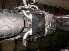
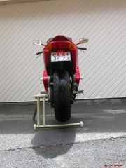
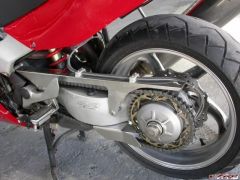
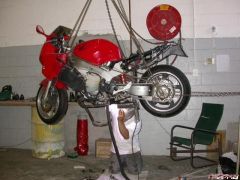
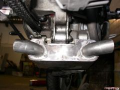
With the muffler now bolted to the bike I was able to tack the stub tubes to the headers & also to the flanges bolted in place on the muffler. Big advantage as everything was aligned before final welding and there is no need to force things into place when fitting it all together ? custom made in situ. Had to trim the stub tubes off level with the flange when all was done (had cut them long so they were sticking inside the muffler when we tacked it all together. welding in the sky 3.jpg I removed the ECU & R/R completely from the bike & disconnected the battery before welding & always had the earth close to the weld. The headers start as 32mm od pipe but change to 34mm od about half way. After the 2:1 join just before the cat-con they are 40mm od. I have used 38mm od stainless pipe because I can get short radius elbows for it; next size up is 50.8 which I felt was too big & there is a space limitation in front of the back wheel so the tighter smaller bend is a help there. 44.5mm pipe is available here but no bends. I hoped the bike will sound like two v-twins running together. The headers are joined correctly for this; two left cylinders join up before the cat-con as do the two right cylinders which is what I wanted. Because I wanted the bike to sound like a pair of twins running together I have made a small port linking the two chambers in the muffler to allow some of the sound from the opposite bank to get across to the other side; I was worried that the outlets face away from the bike so separate the two sound paths a lot. I reasoned that it would be easy to close the port if I was unhappy with the result ? in fact I am delighted ? you can hear there is more than just a potato -potato Hardly here; a much more complicated sound. There used to be a Ducati in my neighbourhood which thudded past with a nice mellow tone. There are several Harleys with open exhausts which I detest. I have made the muffler without baffles but with tubes inside (there is a separating wall down the middle). These tubes are flanged from the outside so I can fit different lengths and also perforate them if needs be. muffler & innards 2.jpg For a start I made the ones in the photos. The muffler is 190mm long so I made the tubes 100 long so the inlets and outlets were just longer than half the muffler length. This means that the exhaust gasses have to double back to get out of the box. When I tried these the noise was too much. Magellan had shown in his write up of his 5th gen under tail exhaust that stainless pot scourers stuffed into the muffler helped reduce the noise so I bought some & rammed them in. Here is one of my posting problems. I had a link to Magellans photo of a pack of pot scourers which causes this thing to bomb-out when I try to post. Magellan's scourers. They are much fuller than mine. I had to ram in 12 per side to fill the space. That helped as it lowered both the frequency & amplitude of the sound but I still wanted it quieter. I tried the perforated tubes on the outlets but that was marginally noisier than the plain tubes. I then made 150mm long tubes for both the inlet & outlet and rammed in as many pot scourers as I could. That is how I am now running the bike. I made a pocket for the suspension linkage on the upper surface. It is 20mm deep but need only be 6mm for the way I have the bike set-up. I am a skinny rat & run the shock on the second softest pre-load setting. I have made a one man paddock stand for oiling the chain & cleaning the oil off the wheel. (BLS, how are you doing with the belt conversion- still no reply from Gates?)
-
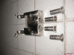
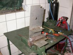
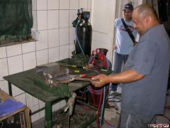
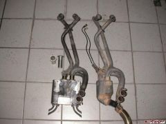
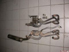
Ah this is the piece that causes the bomb-out so I will split it up more until I find the error. HOW I DID IT I got a spare set of headers posted to me by Trace. I was going to make the muffler out of 0.9mm stainless cold bent to shape. Fortunately I read the thread on de-gutting a 6th gen exhaust where I saw that those mufflers have quite a thick wall. 6th gen de-gut thread Magellan & Lobster answered my query about the wall thickness so I changed to 1.6mm stainless. Now I needed to heat the stainless with oxy/propane to bend it. I had made a bending jig of a piece of 40x40 square bar & 41mm heavy wall pipe bolted together with 2 @16mm bolts. I have CAD/CAM & a cnc machining center so I modeled the muffler & cut the stainless to shape on the cnc machine. I scribed the bend start & finish on the inside of the blank, clamped it in the bending jig, heated it up & hammered it round the jig. Not a success. Gives a very beaten up looking bend. So made a paddle with a sharp edge & welded on 2 extensions to the jig so that I could lever the steel round the jig with the paddle. Tried again ? worked really well. Get very good conformation of the steel to the jig. first bend & jig 2.jpg The first bend has been made. The separating wall between the two chambers was welded in first. Note the port through the wall ? it gives a bit of cross-talk to complicate the sound. The black mark is soot from lighting the torch (looks like a hole) bending jig & paddle.jpg This is Ridwaan who did all the welding. Photo is not very clear. There are two pieces of square steel welded on sticking out forwards. The paddle is used to lever the stainless around the pipe section of the bending jig. Originally I had allowed for a bit of spring in the material when I was planning on cold forming the thinner material. Now the bends have no spring in them so you will notice that the top surface of the muffler is not parallel to the bottom because the blank was cut too long (it allowed for spring at the bends which is not there with hot bending). The divider between left & right does not run down the center line because the headers are slightly offset & the muffler is not centered either. I did not want to bend the headers. The muffler is bolted to the old center stand lugs. I had two goes at this. Initially I welded the flanges directly onto the headers (which had been elegantly cut by Trace just before the cat-con) but that presented problems with fitting the nuts and there is a lug under the engine that the cat-con was mounted to that sticks down lower than the center stand lugs. So I moved the muffler back behind the cat-con lug which allowed it to fit up higher from the ground. I also cut the headers shorter and fitted short stub tubes between the headers & the flange at the muffler. This way I was able to firstly weld on the lugs for mounting the muffler onto the center stand lugs (now free because the center stand has been ditched). original & new 4.jpg Note the little stub tubes between the headers & muffler
-
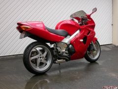
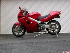
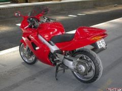
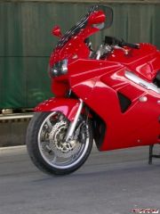
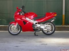
WHAT IS IT LIKE? Wonderful! It is noisier than I wanted. At idle it sounds perfect: no even regular boring purr of a ?stinky I4? (BLS expression, acknowledged) but all lopey, irregular and impatient ? just what I wanted. Give it some gas and it sounds like a box full of angry hornets ? there is a real prospect of carnage if it gets loose ? wonderful; yoohoo, here we go. Below 5000 rpm it is still somewhat civilized but above that it?s a barbarian. So I can ride in my dignified neighbourhood at small throttle openings & short shifting & not disturb the peace; can burble around town below 5000 rpm & not annoy everyone but get out of town & blast about so every motorcyclist in the vicinity will immediately stop what he is doing & try to find out what the fuc? is that? I would like it to be a little quieter. But the sound quality is perfection, just the volume is a tad high. I am delighted with the looks. To me there are 2 defining things about a VFR: SSA & V4. This exposes the rear wheel to the maximum & the sound certainly is distinctive ? just that a wild V4 on the loose is not usually heard. Swiffer coined a nice compound word: audio-cosmetic; this is just that ? I was not looking for performance, just sound & appearance. Must be breathing easier as the idle speed has gone up from 1200 to 1500 with no other changes made & my seat-of-the-pants dyno says it has significantly more get-up-and-go. (I am running the stock Honda air filter.)
-
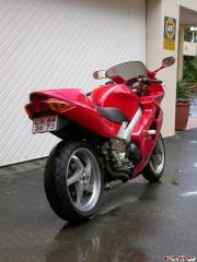
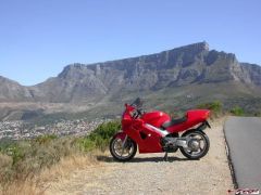
I have made a low level exhaust for my 5th gen. I will describe it backwards; first the end result, secondly how I did it & finally why I did it this way & what alternatives I considered. You can bail out as soon as you lose interest. THE END RESULT RH 1.jpg Before Done RH 3.jpg Done RHR quarter 1.jpg done LH 1.jpg Done behind.jpg . I have taken the center stand off & cut the headers just before the catastrophic converter. I have made a two chamber muffler out of 1.6mm stainless steel with separate right & left low level exit pipes which fits where the cat-con used to be. I wanted my bike to sound like two-small-bore-Ducatis- running-in-tandem and I wanted to expose as much of the rear wheel on the right side as possible. original & new 1.jpg new from below 2.jpg new from below behind 1.jpg . new from RHR quarter 3.jpg
-
First pictures
-
-
From the album: One
-
From the album: One
-
From the album: One
-
From the album: One
-
From the album: One