


chris2992
-
Posts
416 -
Joined
-
Last visited
Content Type
Forums
Profiles
Gallery
Blogs
Downloads
Events
Everything posted by chris2992
-
See above post, modified with pictures.
-
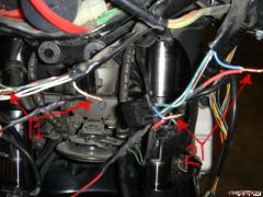
From the album: Technical Pictures
1) New Switch 2) New wiring wraped in loom© ©vfdiscussion.com
-
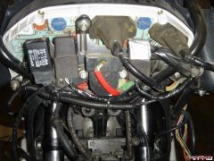
From the album: Technical Pictures
All Soldered, heat shrunk and wraped in loom.© ©vfdiscussion.com
-
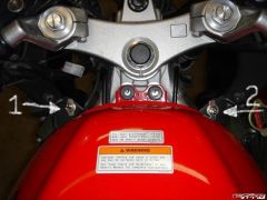
From the album: Technical Pictures
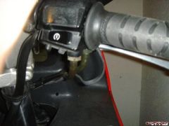
1) Heated grip switch 2) Super Bright Light Switch© ©vfdiscussion.com
-
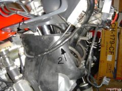
From the album: Technical Pictures
1) Low beam connection, - side of diode 2) High Beam connection, + side of diode© ©vfdiscussion.com
-
The kit you are discribing is how the bike is wired origionally. There is only around 0.1 amps at 13.8v flowing through the switch housing on the handle bar, just enough to trip and hold the relay closed. The current that the headlight draws flows directly from the battery into the switched side of the relay and directly to the headlight. OEM wire from the battery to the relay and from the relay to the lights is 14ga, but each circut only draws around 5 amps, so that size wire is actually overkill. Watts/volts=amps, so 65w headlight/ 13 volts = 5amps. The wire coming from the switch housing is likely around 20ga, but as stated above, it is only carrying signal current, not opperating current. What is being shown in this thread is a way to run both high and low beams at the same time.
-
Digging this one up from the grave. I was working on this last night and here is what I did. The wiring in red is new. Wiring Diagram This is a wiring diagram for having both high and low beams on at the same time. -This allows the OEM high low switch to go from lows to highs regularly, when the additional switch is open. -When the addition switch is closed, the low beams function normaly, because the diode prevents the high beam realy from triggering. But when you flip to high beams, you energize both relays. I liked the idea of staying on the low current (signal) side of the relay, and this seemed the simpleist solution. I have part numbers and pictures at home, I'll update this post with that infromation tonight. Update: All finished up and Everything works perfectly. Wire Tap Location 1) Low beam connection, - side of diode<br />2) High Beam connection, + side of diode Switch Location 1) Heated grip switch<br />2) Super Bright Light Switch Wiring Finished up All Soldered, heat shrunk and wraped in loom. Wiring Finished up 1) New Switch<br />2) New wiring wraped in loom Make sure that you have the + side of the diode on the high beam signal wire. If you have these reversed, when the low beam is selected the high will be on and when the high beam is selected only the high will be on. Exactly backwards of what is needed. The diode I used was from radio shack, got two for $0.69. Part number 1N4001 Micromini Silicon Diode 50V 1A. When checking the voltage on the low beam signal wire through the diode, I have a 1v drop, however this isn't a problem because it is still plenty to trip the relay.
-
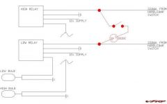
From the album: Technical Pictures
This is a wiring diagram for having both high and low beams on at the same time.© ©vfdiscussion.com
-
Did they fail with results similar to mine? Or what fassion did they fail?
-
Well, stay tuned then, I'll post my results from Ricks as soon as I have some. Probably be about a week.
-
The RR is the new upgraded honda part, and it is around 3 months old, and only 1k miles. So I doubt it to be the issue. Battery is brand new, so I'm doubtful that it is the problem. I can't Understand how it might be the RR, when the stator tests out voltage wise unloaded fine, but under a load, very week. But on the same note, I have never seen a stator fail quite like that. Who knows, I am going to send my stator and RR to ricks for diagnostic testing, hopefully they will be able to make things right. BLS, when you replaced your parts, did you use OEM, or aftermarket? Also did you check the flywheel, I have seen notes on the flywheel actually going bad, unlikely but possiably.
-
Thanks Cooter. I have heard bad things on eletrex products, so I won't be using them. But You saw where I had spoken of Ricks Motorsport Electronics, I am going to call their CS office today and speek with them about my problem and see what they have to say. I'll probably just have them re-wind my stator and possiably run some diagnostic tests on my rr.
-
Battery is brand new, My battery tender holds directly at 12v. I had just taken it off the tender, so that explains the low voltage. As for the resistance between the legs, honda says that it should be between 0.1 - 1.0 ohm.
-
I have been having lots of problems tring to figure out what is wrong with my charging system. Thought it was the RR, wasn't. Thought it was the battery, wasn't. Thought it was the wiring, wasn't. Thought it was the stator, wasn't ..................... But wait, maybe it is. Lets get all the facts on the table. Battery Voltage = 12.3v Charging voltage at Idle = 13.2v Charging voltage at 5k rpm = 12.1v and lower as time goes on. Resistance between battery ground and frame ground = 0.1 ohm Resistance between all 3 legs of the stator = 0.3 - 0.4 ohm Continuity between all 3 legs and ground = none AC voltage from stator (with rr Unpluged) at idle = 19.6v AC voltage from stator (with rr unpluged) at 5k rpm = 65v AC voltage from stator (with rr pluged in) at idle = 11.2v AC voltage from stator (with rr pluged in) at 5k rpm = 4.2v DC voltage at the battery side of the +/- rr Connector = Identical to battery voltage (Bike off = 12.3v / Bike running = 13.2v @ idle, 12.1v @ 5k rpm) DC voltage at the RR side of the +/- RR connector (connector unpluged, measured directly across the red and green wire) at idle = 0.9v - 1.1v DC voltage at the RR side of the +/- RR connector (connector unpluged, measured directly across the red and green wire) at 5k rpm = 0v - 0.1v Static tests of the stator, it checks out fine. However, under a load it seems to show its failure. Also, something that I have noticed is that as the bike warms up, the problem gets worse. Is this normal, and is it the stator, or possiably the flywheel.
-
NOOO, man that stinks. Just be glad that you are Alive and OK. Sorry to hear that.
-
They are adjustable to the hilt too. You can pivot them front to back, up and down, and rotate the mirror as well. But the coolest is that the stalk can be shortened or lenthened, there is a set screw that allows you to pull them in and out. Get them out wide enough for touring, pull them back in for sleak points. I will own a set asap!!!
-
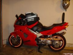
From the album: My Red '99
-
-
 Would look much better if the black wasn't gloss. The shiny takes away from the red body work. Also the red wheels stink, need to be black with a red rim stripe.
 -
WOLF VFR800 owners, need some help.
chris2992 replied to Veefer800Canuck's question in Modification Questions
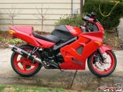
Why did wolf turn the outlets inwards like that. It makes the back of the bike look cross-eyed. Has anyone else noticed that. This comment coming from a very jellous non wolf owner. -
 Do this picture the other way, Lines up top and finished on the bottom. Looking at it makes me feel upside down for some reason.
 -
Maybe I am wrong, but I am almost confident that there were 2 bulbs for each display (tach, speedo and LCD). Fuzzily recalling that maybe the tach and the speedo shared a bulb in the middle?? Veefer??
-
6, I orders 7 for a spare and used it as one of the 6 didn't work. But after Veefers post on polarity, I'm thinking that I didn't turn the bulb around and that could have been the problem.
-
Yes I have the 4 led ones, they aren't too bright, but emit an even light. Our pictures look almost identical, mine is a bit brighter, but that is likely the camera and I was in a pitch black garage.
-
4th Bulb down in the link. WLED 4-LED bulb