chris2992
-
Posts
416 -
Joined
-
Last visited
Content Type
Forums
Profiles
Gallery
Blogs
Downloads
Events
Everything posted by chris2992
-
 :laughing6-hehe: Awesome! Such a Cutie, she surely makes daddy proud! RIP.
 -
SEXY!
-
I'm in the process of restoring a 1971 Kawasaki F7 enduro that hasn't been ridden for approx 10 years and the time that it was ridden (9k miles) was 95% off road. Therefore there is a lot of old baked on grease, dirt and crap. I have tried the Pine Sol parts wash basin, and while it works well for dirt, grease from the chain and swingarm pivot area laughs at the "de-greasing" powers. I'd say that if you have some serious funk going on, that you better spend the jack on real degreaser. On a second note, it appears to take off paint too if left too long. I have been letting parts soak for 3 to 4 days at a time, some parts do two or three cycles, and when they come out after a longer soak the paint is blistered. This may be the fact that it is a 40 year old bike, or it may be the fact that it is paint and not powder, but I don't think that I'd trust my VFR parts in the solution. For reference, my solution is mixed 5 parts pine sol 3 parts water.
-
Sweet, thanks a ton for the info, I'll be picking up a set asap. In reguards to the older model R1RR with the smaller heat sink, I was told that the internals were far less superior to the 04-06 units. Not sure is this is valid or not, but something to think about. Either way I'm sure that both are a vast improvement over the honda peice.
-
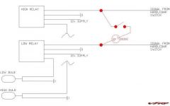
Post the charging system results from the chart on the first post of this thread. That will allow for a proper diagnosis. However I'd say that your RR is smoked. Look for the R1 RR thread how to.
-
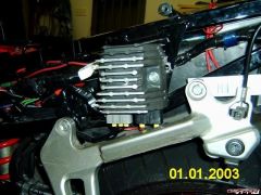
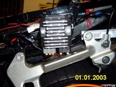
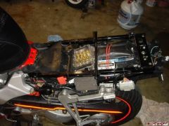
The 04-06 RR was upgraded from yamaha, slightly larger foot print and larger heat sinks. However you have to cut some of the heat sinks off so the end result may be the same. Personally I think that the 04-06 probably runs cooler than the previous ones, but they will likely be so much better than the OEM that either would be a good choice. I just crimped them, but put some di-electric grease in the hole before inserting the wire to prevent corrossion Yes, Yes and Yes. I would not use the OEM connector, it has proven time and time again to be a weak link and you are already altering the bikes harness removing the OE RR. You will still have a "quick disconnect" point at the rr by just unpluging the spades. Hope this helps, if not ask some more.
-
After watching some of the videos on the Blaxey website, I tried to put the bike into the chock by pushing it from the side (the way they do it in the blaxey video's) and it rolls in much easier. And since there isn't as much effort going in, the chock has much less force tring to slide it forward. I have re-done the Plasti dip paint, and am letting it dry, hopefully tonight I'll get to see if it works for sure. I did a few trial runs with the paint that had pealed up and it worked great, now I just have to figure out how to keep the stuff from rolling.
-
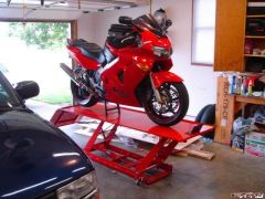
Here is a picture of the bike in the chock and tied down. Here is a short video of me putting the bike into the chock, then shaking the bike, and removing from the chock. The plasti-dip paint just rolled up on the bottom, so it isn't the answer. This is the reason that the chock slides forward when the bike falls into the chock. I have a few more ideas, but if push comes to shove, I'll just install the McMaster bumpers.
-
It is shielded gas, however the tank was nearly empty, and I was having a hard time getting the pressures right. Since welding that, I got a new tank and the splatter is much better. That was one thing that I did notice is that clean is very impportant, if there was any paint residue or anything else on the surface the weld sucks.
-
That is how I learned too, I welded two peices together then looked at the back to see how it changed, then cut it apart to see how much penetration I got. I was getting 3/4 of the metal thickness on most welds that I cut open, so I assume the same here, the back of the metal looks similar. However where I could I welded on both sides to eleminate any concerns. I'll have to post a picture when I get home of the welds before paint. There was no more heat avaliable from my little ole mig, I had her pegged out to get these results. It is rated for materials up to .125" (1/8), which is what I used, but I do agree that alittle more heat and I'd have had better results. Only time and testing will tell if I have any structural concerns, but I'm not too worried, it is strong as an ox and as anal as I am, I'll frequently check all the welds for stress cracks.
-
Just out of curiosity what were you charging, I put a pencil to materials and my time to build a slight variation of this one. There is over $75 in materials and supplies involved in this monster. Plus to build this one I have about 20 hours in it, but figure that I could probably finish one every 6 hours or so (welding, cleaning and paint). So for me to sell these, I'd have to charge minimum of $150, and at that price, you can buy the harbor freight one that I listed above for $90, or stroll over to new enough and pick up the power stand for $120.
-
I got the McMaster bumpers in, and I just didn't like them. They were too small and looked cheep. So I got to thinking about the rubber dip coating for tools and such. Then I found out that you can get it in a spray can, the product is called Plasti Dip, here's the website LINKY. I have only put one coat on, and they suggest 4, so over the next few days I'll post some pictures of the process if it works. After one coat, the surface isn't soft, but it is tacky, so I think I'm on the right track.
-
See first post for attached .dwg file for the chock. As for building one, to even break even on time and getting materials (I'm out of freebies), I'd have to charge too much. Here is a link to one in harbor freight that is built like mine but bolted together ( Harbor Freight Linky ). At $92, it seems like a steal. Thanks for the comments guys. Seb, on this particular one, you couldn't back the bike into it. You could make a second flapper gate that was wider and it would work, or come up with some way to make the side supports on the flapper adjustable so that you could scoot them in for the front and out for the back.
-
That one is quite fun, it is for the nieces and nephews, but I think I have more fun with it. Plus it is quite the lawn sprinkler and cheaper to boot.
-
No blueprints, but I could certianly make some. It was all seat of the pants, and somethings worked and some things didn't. It took about 3 or 4 stabs at the flapper to get it right. I'll get on a B.O.M and some general drawings, but it will probably be tomorrow.
-
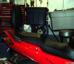
All the materials were free to me, so total cost was $0, my kind of deal. As most can tell, I'm Mr. Frugal (made own backrest, made own luggage system, R1 RR for $20, etc.......), so when it came to wanting a chock for my lift, I knew I wasn't spending $200 bucks on one. So I got to looking at different designs and realized that they are quite simple in design and leave quite a bit of room for tolerances. So I embarked on designing my own out of some scrap steel from my work. I have built this chock to be completely adjustable, you can move the flapper gate forward for smaller tires, or back for larger tires, so anything from my dads goldwing, my buddies vtx and my precious VFR will fit in snug as a bug in a rug. Quite honestly, I have only known how to weld appropriately for a tick over a month, so my welds don't look to good, but I feel quite comfortable with their strength. My father-in-law left his MIG at my house, so needless to say, he may not be getting it back. All that is lacking at this point is my McMaster shipment with the rubber feet to keep it from sliding around on the floor. Enough with the small talk, on to the pictures. Here is the chock, you can see the giant gusset to keep the front channel from wanting to rock forward. Also my Flapper pivots in bronze bushings, so it pivots quite smoothly. Here you can see how the tire clears the gusset, and how the stiffening angles welded to the bottom channel cradle the tire. And here is where I prove that I do in fact have trust in my quasi welding skills. I'd be happy to help anyone out looking to do something similar. My only complaint is that I wish I had my pivot point somewhat lower so there wasn't such a hump to roll over, but that would also compromise the "over center" design. UPDATE: I just attached a .zip folder containing an AutoCAD 2000 detail and assembly drawing of the chock. It is pretty basic, as I don't have too much time tonight. But feel free to ask any questions. A few notes about the drawing and assembly. You can certainly change the assembly process any way you want, however I'd keep the main geometry the same. All material is formed .125" flat stock unless otherwise noted. You'll see where the bottom main channel has the flanges coped off so that the web of the channel slides under the cross support channel. I probably wouldn't do this if I built it again, I was trying to get more surface area to weld, but it is plenty strong and it makes an elevation difference between the cross channel and the main channel. The two angles running parallel on the main channel should probably not be placed by my dimension, set them by the way the tire falls into them (get the chock fully assembled, then roll the bike into it, place the angles along the bottom so that both sides are touching the sides of the tire and mark, remove bike and weld them into place). You can see in the pictures that I didn't do this, and forgot to take into account the metal thickness of the flapper gate. Also if you look closely at the pictures, you will see the shaft going through the bronze bushing, to keep the bushings locked in place and she shaft pinned inside the bushings, I used a 5/8" clamping set collar on each side. This also lets you take both set collars loose and slide one bushing out of the hole and remove the flapper from the channel. On the flapper, where the gussets weld to the side with the hoop, I had to bend that portion forward some, You can see the bend in the pictures, if I had left it straight, only the bottom hoop would have contacted the tire. This however is not a calculated bend, I simply slowly bent until it fit the radius of the tire. Hopefully this makes sense to you, if not, please ask any and all questions. Also if you need the file in something other than a .dwg, about the only thing that I can do for you is make individual .pdf's of each part, but it will be a few days before I am back at my work computer with adobe on it. When my Mc.Master shipment comes in, I'll take a few more pictures of the bottom with the bumpers installed and such. CHOCK.zip
-
Ummm Maybe.
-
-
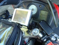
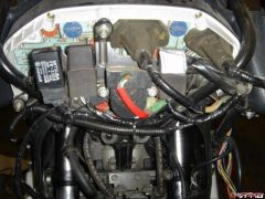
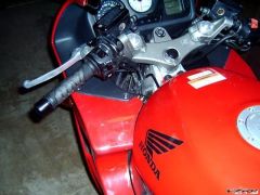
From the album: Technical Pictures
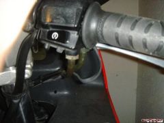
I modified a mount and threaded the base, then fabed a small piece of stainless to mount to the handle bar. Frugal and it works, my kind of mount.© ©vfdiscussion.com
-
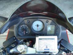
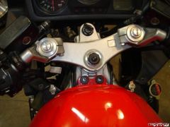
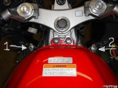
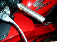
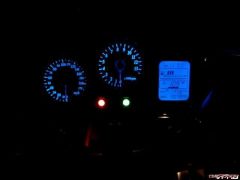
From the album: Technical Pictures
Slightly high, but close, I just barely can't see the FI light.© ©vfdiscussion.com
-
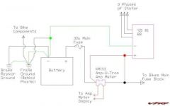
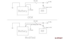
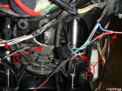
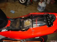
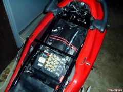
I'm confused is the positive (+) in the inside, or the outside? Busy little shop has the positive on the inside... From the first post.
-
Garage Door Opener Steering Stem Button :thumbsup:
-
Sweet, Glad it is working out for others.
-
Wow, nothing like a complete installation of a lift. I guess I'm lucky that my wife drives a Blazer and can just park over mine. Nice.
-
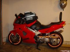
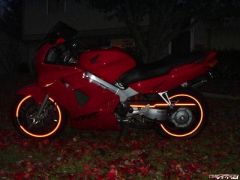
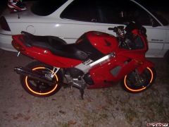
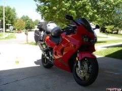
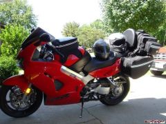
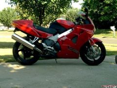
Various Photos of my Baby
-
-