

kaldek
-
Posts
1,317 -
Joined
-
Last visited
-
Days Won
11
Content Type
Forums
Profiles
Gallery
Blogs
Downloads
Events
Everything posted by kaldek
-

Installing 2006+ ECU and motor on 2002-2005 6th-gen
kaldek replied to kaldek's topic in Modifications
Things are progressing folks. I've had the bike apart tonight to look at all the main harness routing points and it looks like routing the new harness through the rear end is going to be such a major pain the butt that I need to remove the entire rear plastic fender assembly. This entails removing the exhaust though, which is annoying more than anything. Ah well! -
That's why you buy the cheap single channel one. If you;'re not going to use it again don't spend more than $60.
-
Not yet - me and Kostritzer were giving suggestions on how to go about it locally. I mean, heck I've got an oscilloscope and low amp current probe but I'm a bit far away. :) Oh yeah, you mentioned a small inexpensive oscilloscope didn't you. Can you shoot me a PM with the brand and if possible a link of a vendor to purchase it from? The shop ones I keep seeing are way beyond the tool budget for now. DSO Nano on eBay. Most of these are clone hardware - no big deal - but there is also a newer Nano V2 and also a DSO Quad which has four channels! All of them are limited to about 1-2mhz, mine realistically tops out at about 150khz before it starts to alias badly. Plenty good enough for auto electrical work though.
-
Not yet - me and Kostritzer were giving suggestions on how to go about it locally. I mean, heck I've got an oscilloscope and low amp current probe but I'm a bit far away. :)
-
Installing 2006+ ECU and motor on 2002-2005 6th-gen
kaldek replied to kaldek's topic in Modifications
Basic wiring harness power test This is the initial test of the US wiring harness. Both the starter relay positive and Main Fuse B positive were wired to the battery along with the main ground wires. No fuses were used - NAUGHTY! I have a USA model 2006 dashboard lying around, so first I checked the clock worked as soon as battery power was applied, and then I jumpered the ignition connector to emulate the key being in the ON position to confirm the dashboard powered up. Before performing this test I had already re-wired the ignition switch to the Aussie 2002 specifications and bypassed the hazard relay. I could not test that yet though as I'd need to strip all the relays off my bike and I honestly couldn't be shagged tonight. Note: iPads are very handy for looking at wiring diagrams! -
Pictures of the process of upgrading my Australian 2002 VFR to a US 2006 ECU and wiring harness.
-
-
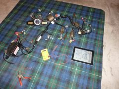
From the album: 2002-2006 ECU upgrade
This is the initial test of the US wiring harness. Both the starter relay positive and Main Fuse B positive were wired to the battery along with the main ground wires. First I checked the clock worked at this point, and then I jumpered the ignition connector to emulate the key being in the ON position to confirm the dashboard powered up. -
Installing 2006+ ECU and motor on 2002-2005 6th-gen
kaldek replied to kaldek's topic in Modifications
Nope! Using a US module would actually require more work as I'd need to buy the hazard relay for it ($50+) and both the turn signal diodes ($13 each) just to get the hazard function. As it stands, my re-wiring job for the right-hand handlebar needed no splicing, just jumpering. The left-side handlebar is the only one that required a little tweaking to make the high-beam-flash work. I'm quite enjoying the process anyway. :) -
Installing 2006+ ECU and motor on 2002-2005 6th-gen
kaldek replied to kaldek's topic in Modifications
Eh? The ground wires for nearly every sensor on the bike don't run through that block, they run through the block in the main harness, between the left-hand side of the engine and the frame. I'll take some pics if you like. The block you're talking about is the sub harness ground block. Not saying it couldn't affect the ECU though - it's just not where the ECU and its sensors are grounded. -
Installing 2006+ ECU and motor on 2002-2005 6th-gen
kaldek replied to kaldek's topic in Modifications
Well, the remaining wiring connectors are taken care of too! Connecting US main harness front brake switch wires to Aussie 2002 handlebar wires OK if pin location in connector block is the same. Black/Green wires from handlebar wires must connect to Brown/Black and Green/Yellow on main harness connector. Order not important. Connecting US main harness engine stop switch wires to Aussie 2002 handlebar wires OK if pin location in connector block is the same. Black must connect to black, and White/Black must connect to White/Black. Connecting US main harness Starter switch wires to Aussie 2002 handlebar wires OK if pin location in connector block is the same. Yellow/Red must connect to Yellow/red, Brown/Blue must connect to Brown/Blue, and Blue/White must connecto Blue/White. Connecting US main harness hazard switch wires to Aussie 2002 bike without hazard lights On main harness, remove Black/Brown wire from hazard switch connector block On main harness, remove Red/Blue wire from two-pin connector block (Red/Blue and White/Red) near hazard block On main harness, join Black/Brown wire with Red/Blue wire. Connecting US main harness clutch and horn switch wires to Aussie 2002 handlebar wiring On 2002 main wiring harness, cut left-hand handlebar two-pin connector from harness with 5cm of wire remaining. On main wiring harness, remove Green/White wire from left-side 9-pin handlebar connector block On main wiring harness, join Green/White wire to 2002 harness two-pin connector block Green/White wire On main wiring harness, remove Light Green wire from left-side 9-pin handlebar connector block On main wiring harness, join Light Green wire to 2002 harness two-pin connector block Light Green wire Connecting US main harness turn signal wires to Aussie 2002 handlebar wiring No change required; handled by turn signal relay and right-hand handlebar wiring. Enabling high beam flash/pass switch to US main harness Purchase new single pin connector block Create new splice wire approx 20cm in length of 10 amp cable Wire one end of splice wire to female side of new connector block On main harness, splice other end of splice wire to Brown/Blue wire at white connector block On handlebar wiring, remove Brown/Blue wire from 9-pin connector block Connect the brown/blue wire from handlebar wiring to male side of new connector block Connecting US main harness dimmer switch wires to Aussie 2002 handlebar wiring No change required as long as pins on either side of connector block match up. Blue must connect to Blue, and Blue/White must connect to Blue/White. -
Hang on. What you're saying means that you know that over-charging the primary coil results in a higher voltage in the secondary winding. Which also means that we're assuming that over-charging the coil is cool. Shouldn't we focus on confirming that's fine first, and then worry about the spark gap adjustment to compensate for the higher voltage?
-
-
Installing 2006+ ECU and motor on 2002-2005 6th-gen
kaldek replied to kaldek's topic in Modifications
Righto, I'm all over this like white on rice. I've designed wiring fixes for the turn signals and also the ignition switch. Next up is the Engine Stop, Starter and hazard switch block, which looks a tad harder. Connecting US sub-harness Turn Signals to Aussie 2002 bike without hazard lights Make jumper wire from 10 amp wire, one end with spade connector, one end bare wire On sub-harness, connect jumper wire blade-end to Left-side hazard diode grey wire socket. On sub-harness, splice bare end of jumper wire to Grey/red wire at Turn Position Relay socket On sub-harness, jumper orange/white to Orange at Turn position relay socket On sub-harness, jumper Light Blue/White to Light Blue at Turn Position Relay socket On sub-harness, tape up all other hazard diode sockets and Turn Position relay socket for weatherproofing Connecting US main harness to Aussie 2002 ignition switch On main harness, disconnect red/white wire from Ignition switch socket On main harness, splice red/white wire at ignition switch socket into Red/Black wire at ignition switch socket -
Installing 2006+ ECU and motor on 2002-2005 6th-gen
kaldek replied to kaldek's topic in Modifications
It's OK. I sat down, had a couple of beers and planned my way forward. It goes like this: Make a list of the circuits with issues. Investigate each circuit's wiring requirements Draw up a plan to re-wire each circuit correctly Whilst twiddling with the sub harness this evening, I attacked one of the circuits I know will have a problem - the indicators. I worked out how this circuit works exactly on my current harness, and so now I know how to wire this one up on the new harness. -
Installing 2006+ ECU and motor on 2002-2005 6th-gen
kaldek replied to kaldek's topic in Modifications
No actually I haven't done that; never had any issues with the front end wiring so never bothered. That connector block BTW is much easier to get to on the 2006+ wiring harness as it's right by the blue and white connector blocks. So if I ever NEED to work on it in future it should be a tad easier. -
Installing 2006+ ECU and motor on 2002-2005 6th-gen
kaldek replied to kaldek's topic in Modifications
Ruh-Roh! This is going downhill rapidly. So, you yanks don't get high-beam flash/passing switches I see! Also your wiring harness seems to route the left-hand handlebar wiring completely differently to the Aussie bikes. Yay! And I see your ignition switch has four wires but mine has three. Yay! Gosh, the right-hand handlebar wiring is all completely different colours too. Ace!!! OH. MY. GOD. I've really dug myself a hole this time. Ohhh yeah. Get out the folks coz this is going be a laugh-fest. -
Installing 2006+ ECU and motor on 2002-2005 6th-gen
kaldek replied to kaldek's topic in Modifications
The "most common" surging is indeed likely caused by the system going closed loop. Fitting O2 eliminators should - if the PGM-FI acts anything like every other vehicle on the planet (and it probably doesn't, coz Honda is "special") - force the system to default back to an assumed reading of 0.5 volts from the O2 sensor, which lets you then tune the fuel injection however you like with your Power commander. If you disconnect the O2 sensor on a car, this is the exact behaviour - it assumes 0.5 volts (14.7 AFR) - but brings up the Check Engine light. Car folks who want to bypass closed loop fit O2 simulators (often called EFIE) which send a simulated O2 signal of 0.5 volts with the right waveform. -
Heh you have eyes like a hawk dontcha! It's my Autotune/map switch for the PCV.
-
Installing 2006+ ECU and motor on 2002-2005 6th-gen
kaldek replied to kaldek's topic in Modifications
Yeah, I'll lose HISS. I'm kinda unsure about how much I care about that. Makes life easier if I ever lose my keys though! Oh, worth mentioning: the 2006+ ECU is freakin' TINY. -
Installing 2006+ ECU and motor on 2002-2005 6th-gen
kaldek replied to kaldek's topic in Modifications
Alright, the parts arrived today (GRATZ SEBSPEED!!!). I've checked the connections and marked all plugs. It's a non-ABS wiring harness, which is good. Things that stand out as definitely needing attention are: This harness has hazard diodes. My bike does not have a hazard switch or diodes. Depending on how my turn position relay is wired up, I may or may not have to do some re-wiring or jumpering. The Vehicle Speed sensor connector is different. No big deal; re-wire job. The indicator plugs are different. Expected this; also no big deal. The license plate plug is different. Also no big deal. I will need to do some wire tracing for the turn signal relays. Might try and do that tonight. I think if I can sort out all the possible issues with the sub-harness I will be in a good position to move forward like a Vector - with both direction and MAGNITUDE. Oh yeah!! -
Which would mean that 2 wire 1.6 ohm sticks will work fine? Yeah, it should mean that, if I'm anywhere near right. Which, I'm also about. We either wait to see what happens with ranger's bike after a few weeks, or he manages to hook up a current clamp to one of the coils with an oscilloscope and we look for a good or bad waveform. All the material I can find points to a reading of 7 amps with a good waveform meaning it's all A-OK.
-
Hey rangerscott, what are the chances of finding someone in your area that could do a current test using a low amp current probe and an oscilloscope on your primary coil wires? If you could run that test, we could confirm if the coils are being saturated or if they're working OK. 7 amps of current with a nice clean "ramp" on the waveform is what we'd be looking for.
-
You didn't RAID-0 your OS drive did you? Naughty!!
-
I suppose this means the Viffer has a closed loop ignition dwell system then. Keep us posted.
-
They do! They're one of very few 3-wire coils that seem to be out there in use on bikes. Not sure what the VFR1200 uses.