

BartmanEH
-
Posts
172 -
Joined
-
Last visited
-
Days Won
2
Content Type
Forums
Profiles
Gallery
Blogs
Downloads
Events
Posts posted by BartmanEH
-
-
Anyone have cad files for mirror adapters? Edit: GSXR mirror adapters or the like.
So many threads with false starts on making adapters. But recently there have been big advances in affordable manufacturing. Thinking about having a crack at this.
edit: Or redesigning the adapters to work with 7/8th gen mirrors—something that officially supports folding.
-
I use this cable to secure electronics or tank bag using a small padlock looped through this cable’s eyelet. Just enough to deter would be thieves from walking away with an item.
-
Respect to you members riding 80's VFs. Wow, admire the passion.
-
 1
1
-
-
On 5/30/2022 at 7:08 AM, Skids said:
QUESTION: Is it just the front 2 bleed valves on the front callipers that need bleeding or is there some way that some air in the rear system, despite the rear brake pedal feeling very good, mean that the front brake lever can be soft and therefore I need to re-bleed the whole rear system again as well? (I appreciate that "front" & "rear" don't adequately describe it as they are linked but hopefully YKWIM).
5th Gen, just in case.
I don't think it's a case of air in the rear brake system affecting the front brake system--it's more that with the Linked Braking System, you've got front brake system plumbing running all the way to the rear brake via the PCV, so you need to bleed the two front brakes, the PCV and the rear brake (forgot which one of the two specifically at the rear brake caliper) in order to bleed the air from the front brake system.
-
Easy now... everyone is just trying to help.
I appreciate all the tips, everyone!
-
I think bmart was replying to my original post where I asked if I should just jam some grease in there
-
10 minutes ago, Captain 80s said:
You can lever the dust seals without damaging them if you are careful and use a good tool.[...]With the seals out you can remove the small seal on the bearing with a very small flat blade screwdriver or pick[...]and pack them with Bel Ray Waterproof Grease.
Aight, let's see how brave I feel about picking apart the bearings. I have a tub of Lucas Extra Heavy Duty Grease. What is the bearing seal made of? Metal or plastic?
-
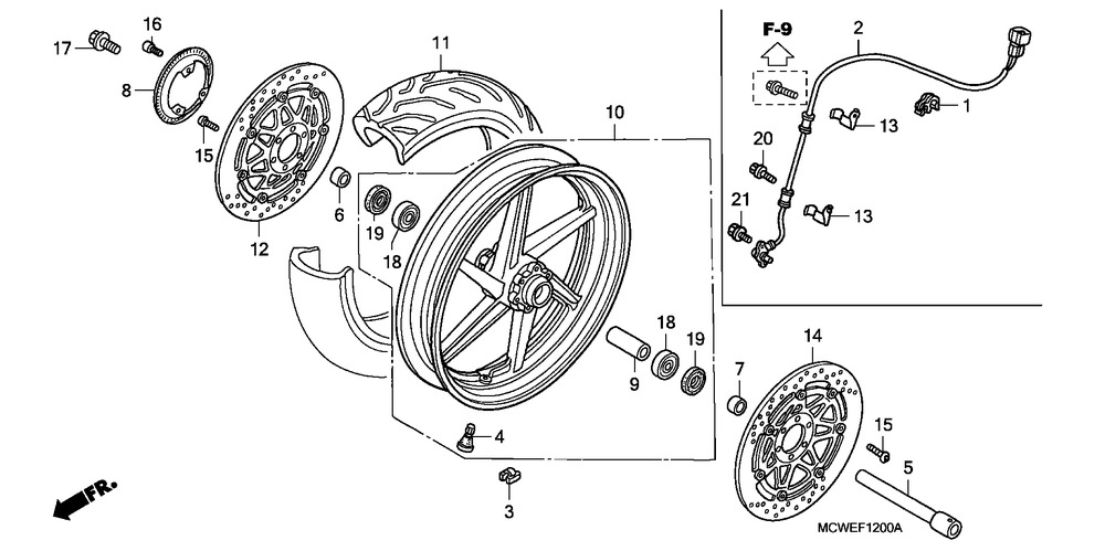
Hard to tell from the microfiche (#18 in parts microfiche) but I certainly see grease in the gap behind the seal.

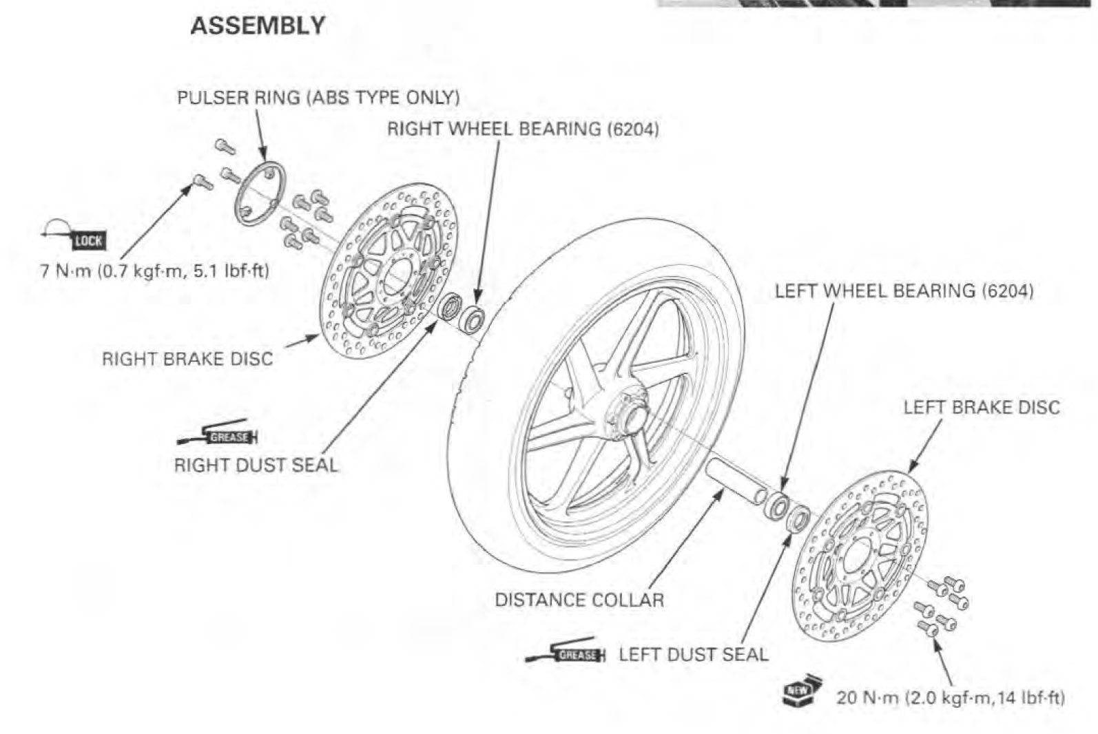
Not much for hints in the service manual either:
Maybe they're sealed as you suggest, @bmart
-
Did a search and didn't find anything about greasing/maintaining the front wheel bearings. Even the service manual has no specifics--just a remove and replace procedure.
I've got the wheels off and new rubber installed. Before I put the front wheel on, I feel I should do SOMETHING to the bearings. I see a beefy dust seal on each side. That doesn't look easy to pop out without damaging it and I'm not sure what the lead time is on replacement new ones here in Canada.
Only have 30,000 km on it (18,500 miles). Can I just jam some bearing grease behind the seal and into the bearing area? Should I do something more like removing the bearings and repacking them?
-
I’m sure Tapatalk support is a sore point. I noticed it was removed as of Oct 2020. Since that thread is archived/closed, I have to burn a new thread to ask if Tapatalk support will be added again.
-
 1
1
-
-
On 5/3/2020 at 4:09 PM, Cogswell said:
[...]
- Close the bleed valve while holding the SMC plunger in. Keep the SMC under pressure - do not release it. [...]
While a PITA, IMHO this is a step that should not be skipped. As we've seen with bikes that have rear calipers that will not release, the SMC can be a villain in that process, so keeping the fluid clean is important.
^^^this. I've asked for this step to be modified in the guide a few times and many people are missing this important step--close the bleeder between actuating SMC and before refilling with rear pedal. I reference this in my short form guide.
-
2
-
On 10/10/2016 at 3:52 PM, RBPOL said:
I am new to this thread. I have taken off the left caliper and am trying to see if pushing on the rear pedal will push out the SMC--it cannot no mater what I try. Suggestions??
This is why I recommend closing the bleeder between actuating SMC and pressing pedal per my short form guide. Closing the bleeder (even if it's a Speedbleeder) and then pressing the pedal will force the SMC back out thus filling it.
-
1
-
-
On 2013-08-20 at 4:55 PM, 2thdr said:
I also put a very thin film of caliper grease on the backs of the pads. That can be a source of squeaking if it is metal to metal. [...]
[Old post I know but people reference this stuff for years]
Do not apply caliper lube or grease to the backs of the brake pads. This is not in the service manual for a reason and our bike's brakes differ from car calipers in this way. More info here: http://www.southbayriders.com/forums/threads/140517/#post-1930527
quote: " you NEVER put grease on brake pads) It also causes the grease to wick into the porous pad material (ruining the pads) straight through to the rotor surface when the back of the pad has been drilled. Some pads are made like this. "
-
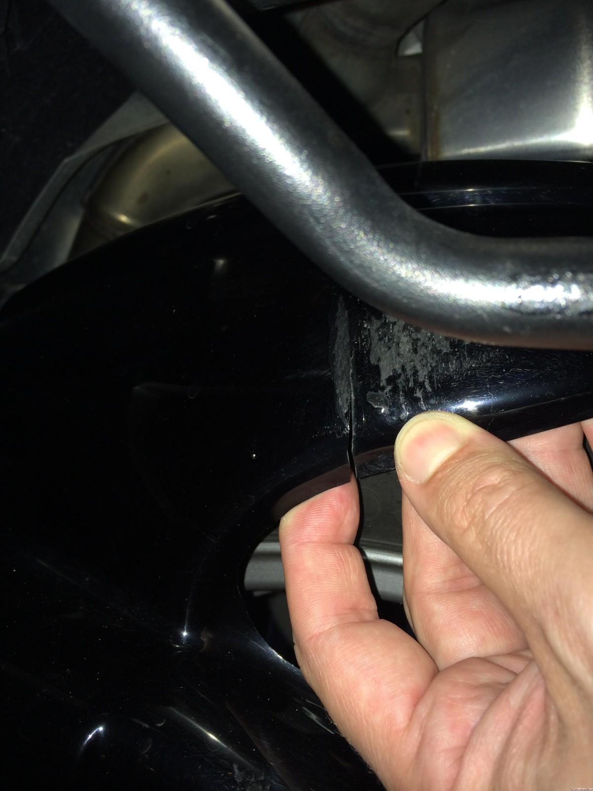
I have the Powerbronze hugger and it is not ideal either. After few thousand miles, it's own vibration caused this crack:
P.S. why is this the only forum where basic things like making a picture smaller are so hard to do?
-
[...]Of those who are interested, what's the general consensus on an upper price threshold? That conversation should probably happen (again) before we continue down this path and end up with a $1XX kit.
Something in the order of $80/pair maybe? I'm Canadian and need to add 40% to that :-(
-
I edited the post above and updated it based on this year's fluid change experience.
-
There are no expected gains until I get my custom dyno tune for my PC3. It does look nice and spaceship like. For now it goes on the list of cheap cosmetic mods.
-
You'll be fine until winter, no problem.
-
But of course. See here. I credit Switchblade with the idea.
-
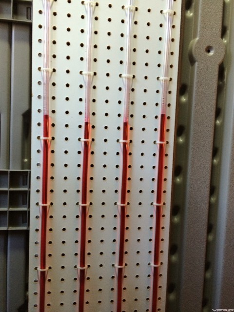
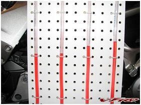
As a follow up to this, I synchronized my starter valves this morning. Here's the before picture of my homemade differential manometer:
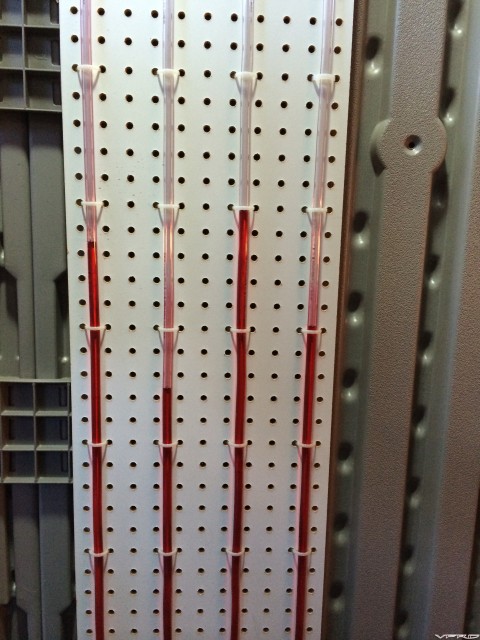
And here's the picture after I synchronized them:
I also calibrated my homemade manometer the day before with my vacuum pump with gauge. I found that if I applied 20 cmHg of vacuum to one of the four lines, it would displace the ATF vertically about 90 cm in that one line relative to the other 3 which I temporarily connected together. Some quick conversions and calculations later, this means that 10 mmHg would show as a vertical differential of 9 cm = 3.54". I have figured out that the peg board with it's 1 in hole spacing would show a 1 in differential of ATF (hole-to-hole) which equals 2.82 mmHg (10/3.54=2.82).
It's been 14,000km (8,700mi) since I last synchronized the starter valves. Looking at the picture before I sync'd them, I estimate that the worst offset (#2 vs #3) was different by 7.5" of ATF = 7.5 x 2.82 = ~21 mmHg which isn't really that bad since that's within the offset limit permitted for the fifth gen anyway, right? The service manual for our sixth gen doesn't specify a tolerance for what the maximum differential should be.
Also note for us Power Commander types, I used the Dynojet Power Commander software to monitor the idle speed and kept adjusting it to 1,200 RPM for the synchronizing procedure. My VFR's tach gauge is very accurate as it turns out. I could've used the bike's tach in the end - when the needle was sitting just one division above 1,000 RPM, the PC software was reporting about 1,200 RPM.
-
I went ahead and insulated the top of the air box too:

I'm planning to get a dyno tune for my Power Commander 3 and this seemed like a cheap and easy mod to help get cooler and hence more dense air into the air box. -
There's no doubt that water enters the air box:
No water will enter the air box, mine has never had any water in it. It has been gone for almost 5 years..I don't see how removing the snorkle can cause water to enter the air box. The air box is under the tank, on top of the engine and behind the frame.It looks pretty protected to me besides where do you think the air for the flapper comes from if honda put the snorkle on the air box to keep out water wouldn't they have added one to the flapper as well?!

This photo was taken after a 9 day ride around Lake Superior that included gravel roads in the rain. The dirt and gravel dust covers the entire flapper shelf and snorkel innards and extended a bit around the inside of the lid of the air box. It's been cleaned which is why you only see the dirt in the not-easily-accessible parts.
After my ride around The Rock (Newfoundland) in 2012, I cleaned out fine gravel from around the air filter which was dragged in through the snorkel and de-flappered vent.
I'm sure Honda designed our bikes to handle some drops of water etc.
-
I think my next mod to the air box will be to cover the entire air box with that stick thermo blanket stuff. Try to insulate the air box from the heat of the engine .
Like this?
I did the bottom half of the air box today. Not sure I'll bother with the top which is pretty much getting enough cool air on it.
-
This is a repost of my original post of June 16, 2008 since I cannot find the original post anymore (VFRD problem?)
I’ve been suffering from the reasonably well documented surging problem with my 6th gen 2006 VFR. At small throttle openings, the bike was surging. In neutral, I could not get it hold any steady RPM in the 2K-3.5K range. It’s not my wrist as I have a throttle lock and it does this with the throttle lock engaged too.
This has been pretty well documented on the Honda VFR Club (UK) site in the thread “Vtec fuelling/throttle control problem - a new hope.” (http://www.bikersoracle.com/vfr/forum/showthread.php?t=44763). This is a painfully long thread with 460 posts and some 31 pages long spanning April, 2005 to today. I’ve worked my way through it a few times and, like any long thread, it goes off on tangents and comes back once in a while. Reading it did convince me that my surging problem could be somewhat reduced, if not eliminated, by synchronizing the Starter Valves.
After seeing Darth Bling’s great DIY differential manometer for synchronizing Starter Valves (http://www.vfrdiscussion.com/forum/index.php?showtopic=16200), along with some other brave folks, I thought I’d have a go at this.
I decided that the right thing to do for my bike is to sync them flat – the overwhelmingly favourable conclusion for the VTEC (as opposed to the pre-VTEC which has offsets in the sync). This is good news for us VTEC owners because it means that you don’t need any accurately calibrated absolute vacuum gauges for this job, just a simple differential gauge. This is where the homemade DIY differential manometer idea really shines.
I also decided that I would keep as much as possible connected and operating during this procedure. The service manual would have you disconnect the PAIR valve and plug the reed valve cover. Other various guides and posts would have you also disconnect the MAP Sensor (sometimes), disconnect the IAT Sensor, disconnect the Variable Air Intake Solenoid, etc. Some posts complain that the idle cannot be adjusted once these various items are disconnected and other posts complain that the settings like idle and probably Starter Valve sync change after reconnecting everything. So I figured the best way to keep as much connected as possible so that the bike was operating as close to normal as possible.
I set about collecting and purchasing the bits and pieces for my version of the DIY differential 4-way manometer:
- 45’ of 3/8” O.D. 1/4” I.D. vinyl tubing
- 3 x 1/4” TEEs
- 3 x 1/4” elbows
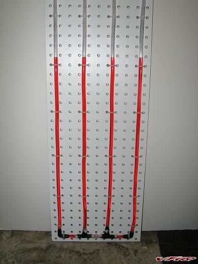
- 1’ x 4’ white peg board
- 5 x 1/8”-1/4”-3/8” adapters
- ~1 cup of ATF oil
- 4 x MIG welding contact tips with 0.025” wire hole
- ~50 tie wraps
Neatness counts. That’s just my opinion. Furthermore, I plan to use this jig again in the future so I wanted it neat, storable and functional.
Notes:
- ATF because it has a nice red colour for contrast
- ATF because it is viscous enough to assist with damping the pulsating vacuum from the throttle bodies
- White peg board for contrast with the red ATF
- Peg board because it’s cheap and has nicely spaced holes for the tie wraps
- White peg board for good contrast with the red ATF
- 1/4” I.D. tubing so it was substantial enough to resist kinking
- MIG welding tips with smallest available hole to be used as dampers as they fit perfectly inside the tubing
Constructions details:
I used 10’ of tubing for each of the four manometer lines for each of the four throttle bodies. I wanted to be sure that I would have time to shut off the bike before any ATF got sucked up into the throttles should something go wrong. Also, the longer the line, the more vacuum pulse damping there would naturally be, albeit minorly at the expense of response time.
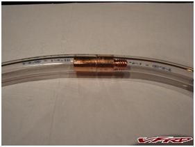
Here’s a close up of one of the MIG welding contact tips inserted in one of the four lines:
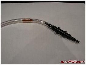
Here’s a picture zoomed out showing one of the 1/8”-1/4”-3/8” adapters at the end of line ready for connection to the throttle body vacuum line.
I wrapped the joints - where I cut the tubing to put in the MIG contact tip dampers - with Magic Tape to make sure there was a good seal there. Magic Tape is really great stuff and I use it all the time. It turned out to be really necessary for other joints in my jig which I’ll get to later on.
Once I had constructed the main jig and successfully got four lines attached to the peg board, I decided that the best way to keep the MAP Sensor enabled/connected was to tap off one of the lines with another TEE to make a fifth vacuum connection to go the MAP Sensor. I tapped of the #4 manometer line since this is the reference Starter Valve and is not to be adjusted in this sync procedure. Here’s a picture:
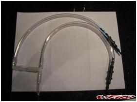
Here’s the bulk of the jig:
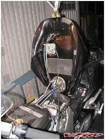
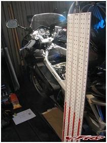
First things first - tear apart the top of the engine area. I suspended the fuel tank vertically from the roof joists of my shed:
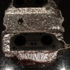
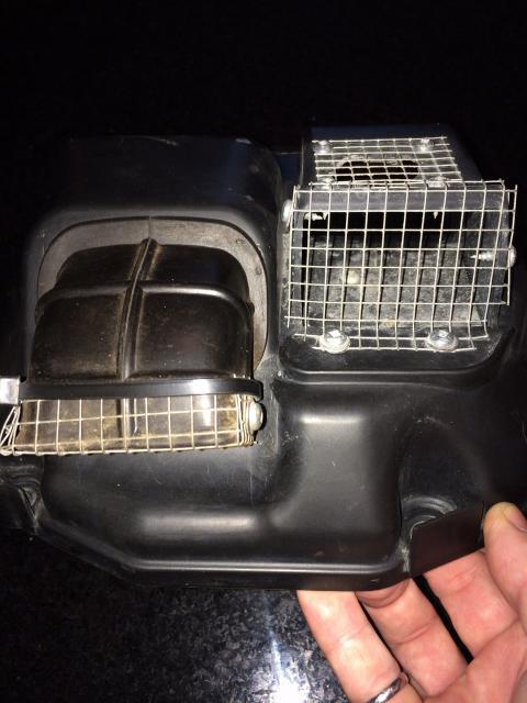
I then proceeded to take apart the air box for the first time since taking ownership of this slightly used (~2,600km) VFR in April only two months early. Well imagine my surprise when I found this on top of my air filter:
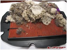
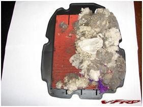
It looks like a mouse made a nest in the top of my air box, probably some previous winter when the previous owner winterized and stored it himself. I’m going to have to write another post about my forthcoming mod to add anti-critter screening to the air box snorkel intake. The nesting material was covering at least 2/3 of the filter area. Granted it was nice fluffy stuff and likely breathed a fair bit and was not completely blocking off that part of the filter but still, there must have been some detrimental effect to that.
After cleaning the air filter, I rigged up my jig next to the bike:
I disconnected the 5-way vacuum connector and connected up the jig’s manometer lines:
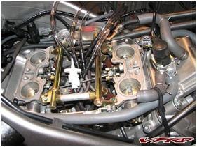
You can see the stark white IAT Sensor in the middle. I removed it from the bottom of the air box so I could connect it up. Same with the PAIR Valve, MAP Sensor and the Variable Air Intake Solenoid – all removed from the air box and connected back into their respective circuits. It’s not easy working under the air box to remove the sensors – it’s a tight spot and hard to do even with a stubby Philips screwdriver.
I actually did a test run and warmed up the bike without any ATF in the jig. I wasn’t sure if I had everything hooked up properly and wanted to be sure the bike would start and run without risking getting ATF sucked into the throttles. I understand that this wouldn’t be a total disaster but I don’t like the idea of ATF oil coating the throttle bodies, Starter Valves, etc. After a successful “dry” run, I loaded up the jig with ATF about 1/3-1/2 way up the lines, leaving plenty of room for the differential readings.
Here’s a picture of the initial readings:
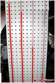
The differential between from the reference Starter Valve #4 was so great that I couldn’t get it onto one picture and had to merge two pictures together to show it! I haven’t done the research yet to figure out how an inch of ATF compares to an inch of mercury in terms of pressure/vacuum. However, even without doing the conversion, one can see that the difference is way too much.
This is where the fun started. My #3 line had a few leaks in the TEE at the bottom of it. I tried adding tie wraps to no avail. Apparently the <$3 plastic TEEs I had found where not very high quality and allowed air to get sucked into the jig in various spots. Even though they had 4 barbs per fitting joint and I had to use a heat gun on the vinyl tubing to soften it up enough to get over all four barbs, they still leaked. I ended up using Magic Wrap on all the connections to render them air tight. Here’s a close up of the Magic Wrap doing its thing:
Eventually I got it airtight enough to be able to take readings, however, I think I need to replace all the fittings before I use it next time because even a small leak, say up at the TEE that splits off for the MAP Sensor, will throw off the accuracy of the whole procedure. Oh well, I’m sure that in the end, I will have made the synchronization much better even with any minor flaws/leaks in my jig.
So I proceeded to start synchronizing the Starter Valves. This takes quite some time. You need to iterate the settings of each Starter Valve a lot to bring them all close to synchronized as represented by a level fluid line across the four tubes. Because this is a differential manometer, changing one Starter Valve basically affects all the others. You need to blip the throttle between tweaks to help the Starter Valves to settle in. I manually pulled on the Wax Unit tie rod in the middle of the throttle body area to help reseat the Starter Valves. This causes some disconcertingly loud air escaping sound and hopefully doesn’t damage, anything like the Wax Unit actuator itself, but I found that blipping the throttle on its own didn’t really affect the Starter Valves in any way and didn’t seem to re-seat them satisfactorily. The Starter Valve adjustment nuts are sensitive – just gently pushing on the set screw nut sends the manometer readings soaring – so you want to be sure they’re getting re-seated in their natural resting spot before making further adjustments.
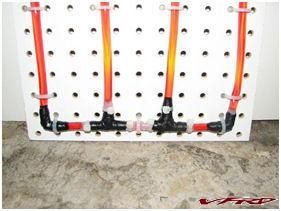
Eventually you get a feel for this and eventually I got them to line up something like this:
They were closer after some throttle blips and out roughly like this at other times. This is as close as I bothered to set them at 9pm on a Sunday night. Further iterations were making things worse so I left it at this.
I also took the opportunity to take out as much slack as possible on the throttle cable. I did this at the throttle body end since it was all apart and easy to access now. I managed to pretty much get all the slack out and tested the full range of motion of the steering to make sure that at either the left or right extreme that the throttle cable wasn’t so tight that it would get actuated purely by the action of steering.
Conclusion (A.K.A. test ride time):
There is an unbelievable difference with the bike now. It’s like a completely new machine. Firstly the sound – it has a beautiful new roar as you throttle up from idle to 5K. From 5K up I found everything pretty familiar. This new sound I attribute mostly to the cleaned air filter and figure now that the engine can breathe fully, it’s generating more power. The Starter Valve sync might be contributing to this new sound too – with a nicely balanced power roll on, the engine is performing much more efficiently and I would expect this could be audible.
Beyond this let me tell you that the small throttle opening surging problem is all but gone. I can coast down to idle in first gear without surging nor does the bike sound like it wants to stall. I can roll on the throttle again with pretty darn smooth response. Neutral RPM test is much better – I can almost any RPMs I choose now – but it still likes to jump up from 2500 to 3000 RPM.
This servicing was worth every minute of time it took in preparation and execution. As soon as the bike exhibits the surging again – and I expect it will as it breaks in more – I will be back into it with my DIY jig syncing those Starter Valves.

LF mirror adapter CAD files
in Sixth Generation VFR's
Posted
GSXR adapters. (Extenders are available a dime a dozen now, OP edited for clarity)