


toro1
-
Posts
470 -
Joined
-
Last visited
-
Days Won
2
Content Type
Forums
Profiles
Gallery
Blogs
Downloads
Events
Everything posted by toro1
-
Well, it looks big...until you compare it to that monster of a stock airbox: intake_comparo.jpg As you can see, the new intake is no higher than the old one -- plus, it's sticking up an extra 1/2" in the air due to the runner tubes that sit down inside the throttle body. You can imagine how much room there would be if I was able to go with the side feed entrance. Just goes to show, size is all relative
-
From the album: The New Mods
© ©vfdiscussion.com
-
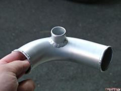
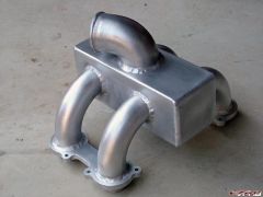
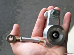
The last of the major fabrication is done. All that's left to do is make a few brackets here and there, and put her back together. Take a look see: idler_assembly.jpg welded_intake.jpg intake_tube.jpg
-
From the album: The New Mods
-
From the album: The New Mods
-
From the album: The New Mods
-
Well, if you put it that way... :beer: :beer: :beer: :beer: all around! (it's much cheaper virtually) I really was worried; all I could think of was "oh great, I've gotten this far and now it's never going to run again." Luckily, I realized the problem was in fact a non-problem. Okay, now back to the garage...
-
Soon my man, very very soon.
-
I Will Never Wear A Mesh Textile Jacket Again!
toro1 replied to SEBSPEED's topic in Clothing & Wearables
Damn dude, that sucks. I'm glad you're okay though! I can completely sympathize with you since your crash story (and bike) in many ways resemble my own wipeout last year. The total disgust I felt looking at my battered bike -- which I spent countless hours fixing and customizing -- was almost too much to take. I put it out of my head for a while, and you know what, it's turning out okay. Hmmm, do I feel a Sebercharger coming in the near future? The bike can always be fixed -- you can't. Once again, glad to hear you're okay. --Dan -
UPDATE: After a vast amount of worrying, time lost, fuses blown, voltages checked, components swapped, switches taken apart, and wiring diagrams read, the problem folks was that the throttle body wiring harness was not plugged in. That's it. What confuses me now is why the pump turned over before when I had it unhooked. Who knows, but I guess this goes to show just how interconnected this bike really is. The moral of this story is before you get all tied up in a what you think is a terrible electrical problem, be sure to have the stupid plugs plugged in. :pissed: Okay, back to finishing this bike up!
-
Okay, I double checked the kill switch, and it's perfectly fine, and as far as I can tell, the bank angle sensor is good too. This bike used to run like a champ, which makes this problem all the more mysterious. This just in: I think I found out why the kill switch seemed like it wasn't working -- I blew a 20A fuse. I'll run out to the store and pick some up, and report the findings in a bit.
-
Very, very interesting Steve. When I got the bike, it had a Gorilla alarm on it -- looks like I have to double check where they tapped into the power. It sure sounds like a similar situation in certain regards...
-
I'll have to try that when I get home today. I also want to check my kill switch out and make sure I didn't blow any fuses since I first started testing, because like I said, initially the power commander would power up every time I flipped the switch, and now it does nothing.
-
The pump is fine -- the problem is that I'm not getting any voltage to the pump. As per the manual, I checked the voltage across the pump connector pins which, for the first few seconds after you flip the kill switch, should read 12V. I see nothing. Zero. The furthest I could trace it to is the fuel pump relay. I'd also like to point out that I have checked the operation of said relay and it works fine; in fact, I even tried replacing it with another relay and still got nothing. From looking at the wiring diagram, the ECM sends a signal directly to the relay to energize the relay coil, which is why I'm concerned that internally, something might be wrong with that black box. I can't check if it's passing proper voltage since I don't have a fancy Honda-tech pin-box jumper-connector-thingie. I'm stumped and completely frustrated. Anybody have an extra ECM laying around??
-
I just reset the computer and unplugged the power commander -- nothing. I'm not even getting voltage to the fuel pump relay anymore.
-
I'll try that Ken, I already did reset the fault codes (quite a few come up when no sensors or injectors are connected).
-
As many of you know, I'm trying to get my bike up and running ASAP. So, to make sure everything would go smoothly prior to final assembly, I decided to test my fuel pump out the other night just for kicks. Now keep in mind, when I first wired in the Walbro pump, I tested it and it functioned perfectly. This time, however, I flip the kill switch to run and nothing happens. I try it again. Nothing. I flip it on and off a few more times and what do you know, the pump works like a charm. I flip it on and off 3 more times to make sure everything is okay, but on the 3rd time, it stops working, and has not come on since. By now I'm thinking that either the pump is bad or a fuse is blown, but closer inspection with the voltmeter lets me discover that the pump isn't receiving any voltage. Nada. I open the Honda manual and, believe it or not, there's actually a checklist of what to do if the pump isn't receiving any voltage: check the main fuse -- it's fine check the other fuses -- they're fine too check the fuel cut relay, the fuel pump relay, and the bank angle sensor -- they all work great check the kill switch -- I see the Power Commander turn on & off everytime I flip the switch, so that's fine as well This leaves only one aspect left to check - and I can't even check it -- the ECM. According to the wiring diagram, the fuel pump relay only activates when sent a signal from the ECM, so right now I'm thinking that my computer took a dump. Also, for some reason, the power commander & knock light no longer light up at all when flipping the kill switch, when just a few minutes before they were working fine. Has anybody ever encountered a problem like this before? Has anybody's ECM ever gone bad? This is so incredibly frustrating to be oh-so-close to starting this bike up, and now having the most important part of the electrical system crap out on me. By the way, I unplugged all the gauges and the problem persists, and yes, the battery voltage is fine. Any help/input/suggestions would be greatly appreciated!!
-
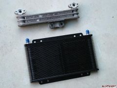
oil_cooler_comparo.jpg Old cooler on top, new cooler on bottom. Pretty self explanatory, no? BTW, the new cooler is about half the thickness of the old one.
-
From the album: The New Mods
© ©vfdiscussion.com
-
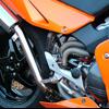
Someday, hopefully, I'll get around to doing the single-nut hub mod, so I can slap on a rear mag wheel to match the Marchesini mag front I have on there now. It's incredible how much turn-in and steering effort are improved by slapping on a lighter hoop, so if I can remove even more rotating weight from the rear (combined with suspension mods), this bike will be an absolute dream to ride. PS -- the linked picture was taken moments after I got the bike together, so please refrain from the usual poultry-related comments... :D
-
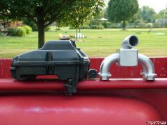
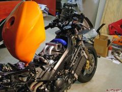
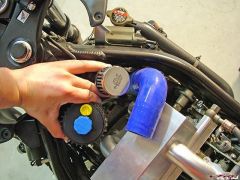
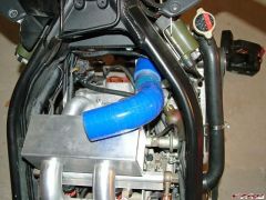
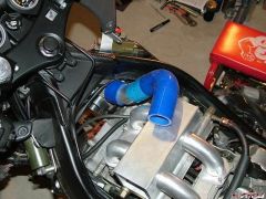
:lol: Hey, people are just excited, right? Anyway, I figured out the intake (yes Dan, I think your technique worked :thumbsup: ). First, let me show you the original plan: intake_design_1.jpg As nice as it would be to run the intake along the side, it just isn't happening. You can see here that while it looks like there's room, remember that the silicone 90 is sticking inside the plenum about an inch, so when you put it in its required location, the bend becomes less than ideal. Also, the T-piece, which I thought would simplify things, only made the setup more complicated and crowded. Thus, we look at design #2: intake_design_2.jpg intake_design_2-2.jpg It's oh-so-simple -- a silicone 45 will come off the blower (aluminum in picture) and attach to an aluminum 90 (silicone in picture), which then will meet up with a close-radius cast aluminum 90-degree elbow (not pictured) and go straight into the top of the plenum box. Equal air distribution and fewer parts are the results of this revised intake, as well as smooth bends & easy assembly. The only downside is now I have to weld a nipple onto the aluminum section for the bov, but that's no biggie. Pictured below is where the oil canister and bov will go: oil_canister&bov_location.jpg Hey, it's ready to run! -- okay, maybe only in my mind, but it's starting to resemble a completed bike once again. ready2run...not.jpg
-
From the album: The New Mods
-
From the album: The New Mods
-
From the album: The New Mods
-
From the album: The New Mods