Search the Community
Showing results for tags 'usb power'.
Found 3 results
-
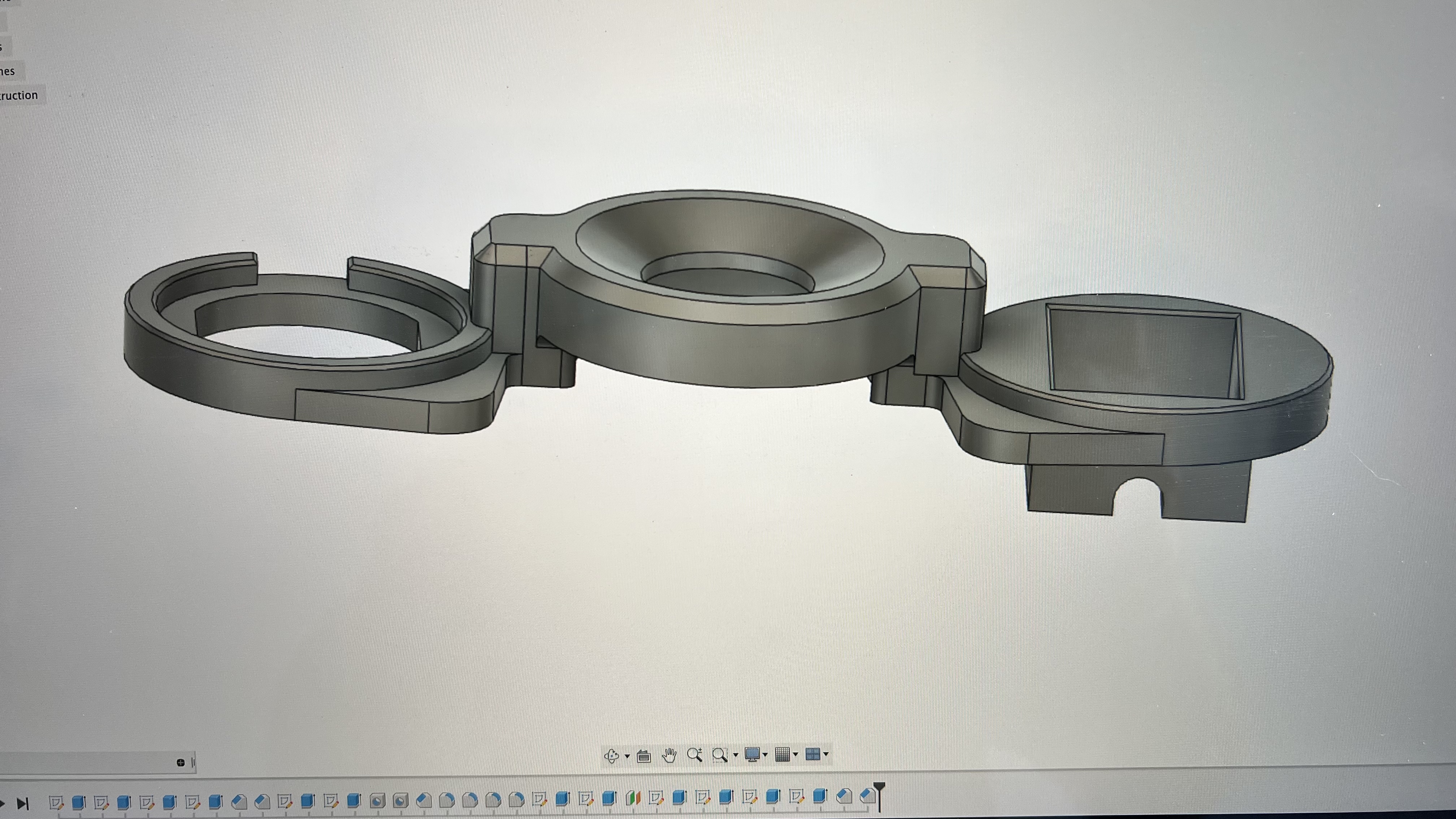
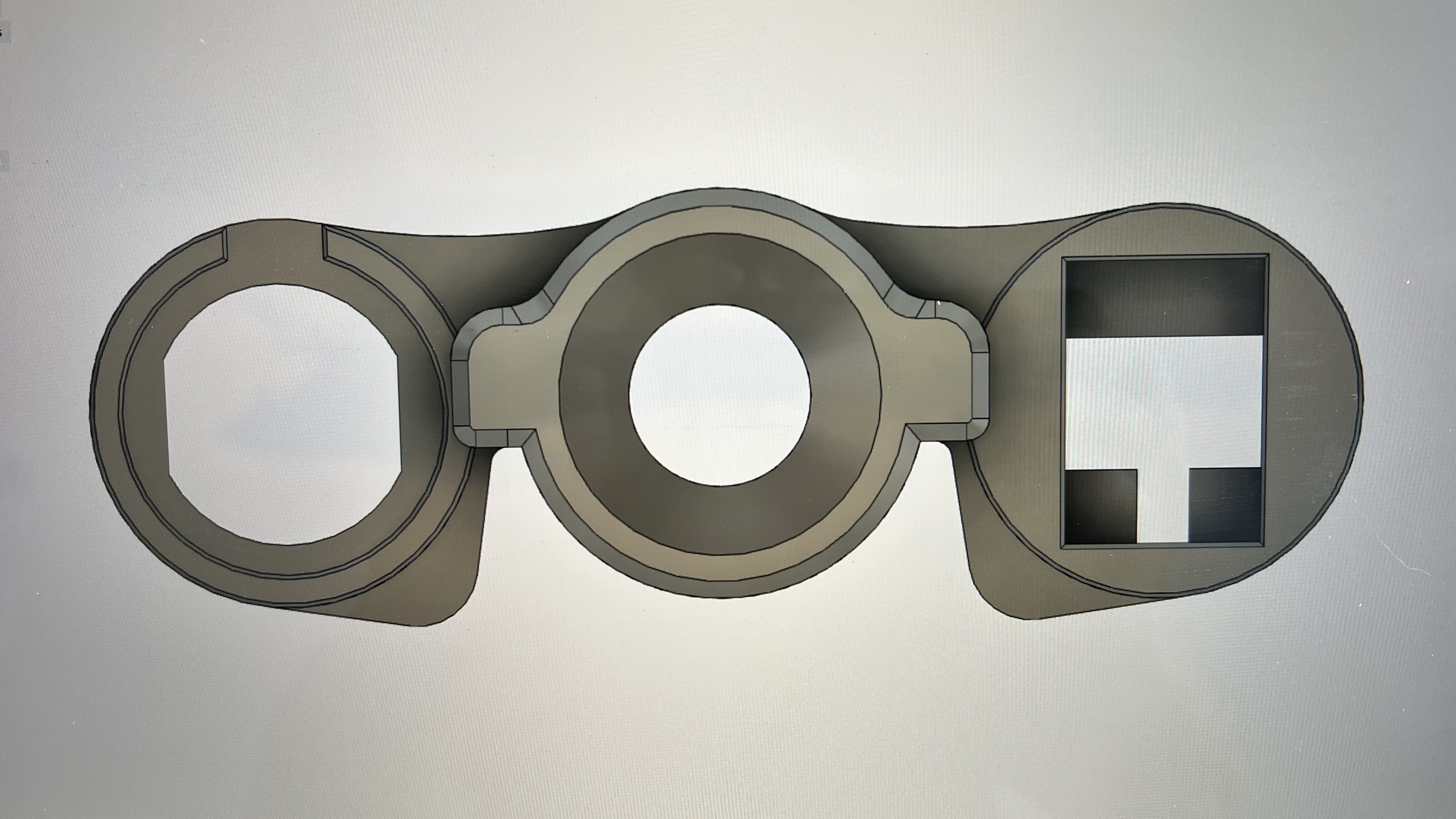
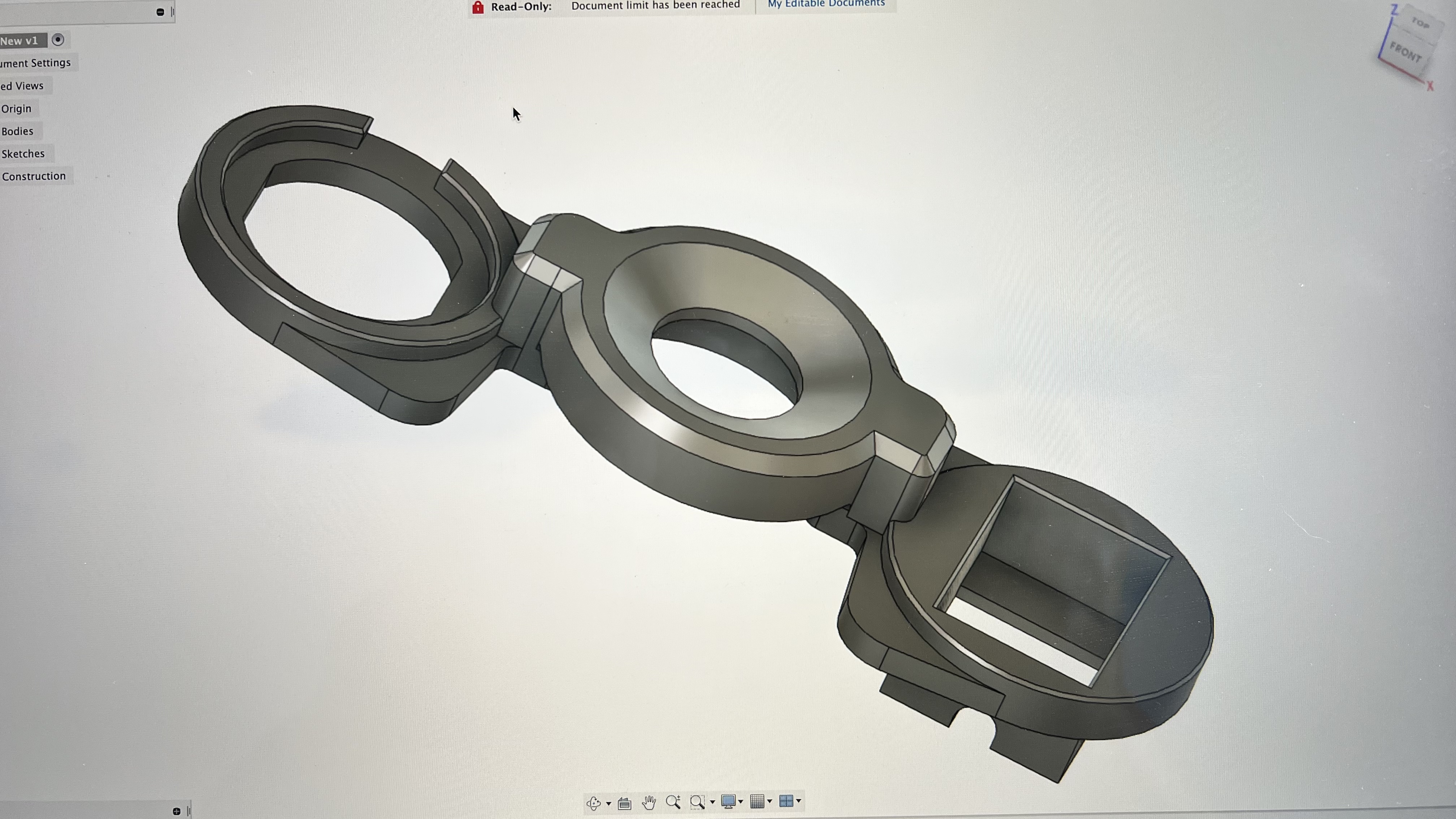
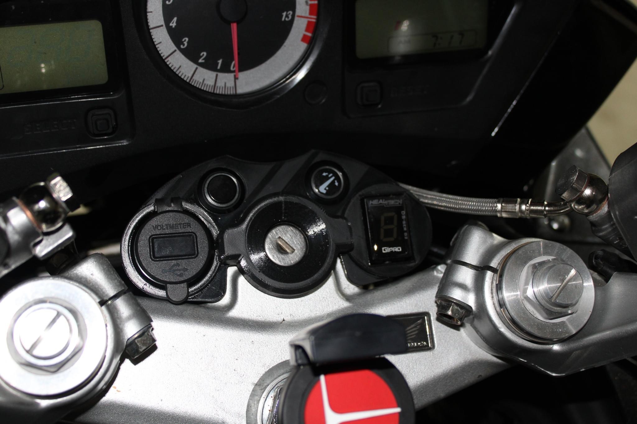
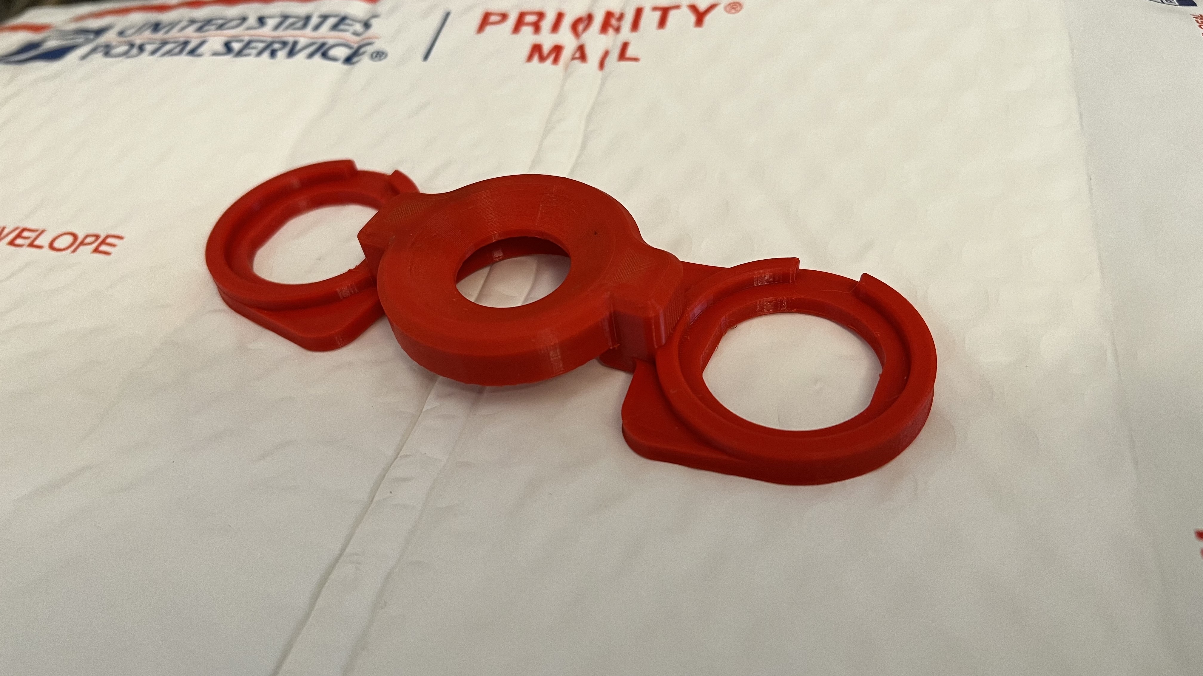
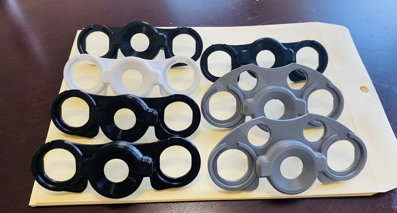
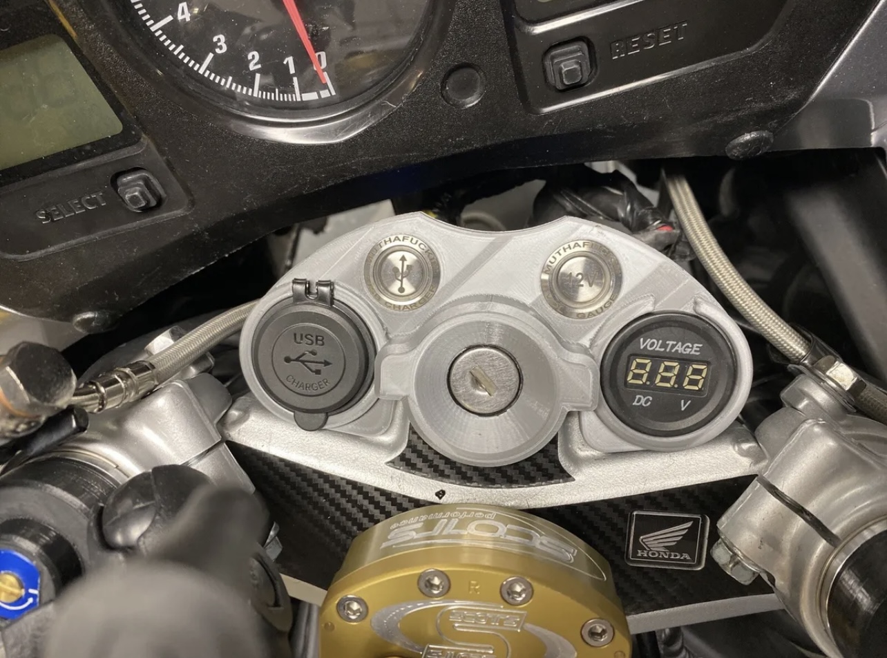
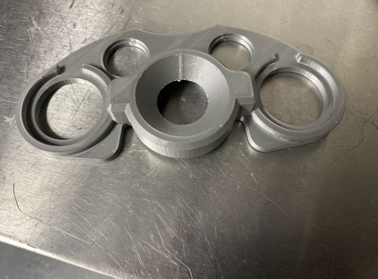
Hi everybody! I’ve had tons of people tell me I should post this this on the VFR forums, so here you go! VFR800 Gear Indicator Bracket. These brackets are designed to replace the black plastic ring on the key cylinder of a 2002-2009 Honda VFR800 (Non-HISS). It is designed to house a Healtech Gear Indicator, and a USB Charger port or volt gauge. It requires removal of the two screws, and then simply remove and replace the ring with this one, then install the new stainless allen screws (included). PLEASE SPECIFY COLOR, THE SUDE THAT YOU WANT THE GEAR INDICATOR ON, AND WHETER OR NOT YOU WOULD LIKE IT WITH THE BUTTON HOLES, OR WITHOUT WHEN ORDERING. I can make them without the buttons as well (see my listing for F4i Charger Bracket for photos; it will look the same, but fit the VFR). There is a wide variety of USB chargers (not included) that will fit this bracket. There are also voltmeters (pictured) that fit. The following link is for the charger that I have used for several years. The same manufacturer makes the voltmeter, and they are all available in a variety of colors. These brackets are 3D printed from a durable PETG plastic, and I can make them in gray (pictured), black, white, yellow, red, blue, purple, or green. If you want a custom color, please email me and I’ll see if I can make it happen. PLEASE SPECIFY COLOR, THE SUDE THAT YOU WANT THE GEAR INDICATOR ON, AND WHETER OR NOT YOU WOULD LIKE IT WITH THE BUTTON HOLES, OR WITHOUT WHEN ORDERING. Disclaimer: No 3D printed part is ever flawless. It is guaranteed to fit perfectly, but not guaranteed to be without minor cosmetic defects. For examples, please examine the photos carefully. That part was installed right off the printer and is representative of a typical part. VFR VFR800 Honda Motorcycle USB Charger phone charger gear indicator https://www.ebay.com/itm/125527979784?mkcid=16&mkevt=1&mkrid=711-127632-2357-0&ssspo=z6UO-uFgTjG&sssrc=2349624&ssuid=z6UO-uFgTjG&var=&widget_ver=artemis&media=COPY IMG_2874.MOV

- 5 replies
-
- 2
-

-
- gear indicator
- bracket
- (and 2 more)
-
Hi all, So I've decided to upgrade the bike for long hauls by adding a GPS mount and power outlet to my 2009 ABS. I didn't have any room to mount the power outlet on the inner fairing plastics because the ABS module takes up so much room. I'm working on creating a new mounting bracket to hold either a power outlet or USB, or combination of the two. I'll hopefully be working on the prototype this weekend depending on the weather and other commitments, but here is the solution I have come up with so far. As I progress I'll update you all with pics of the completed project
-
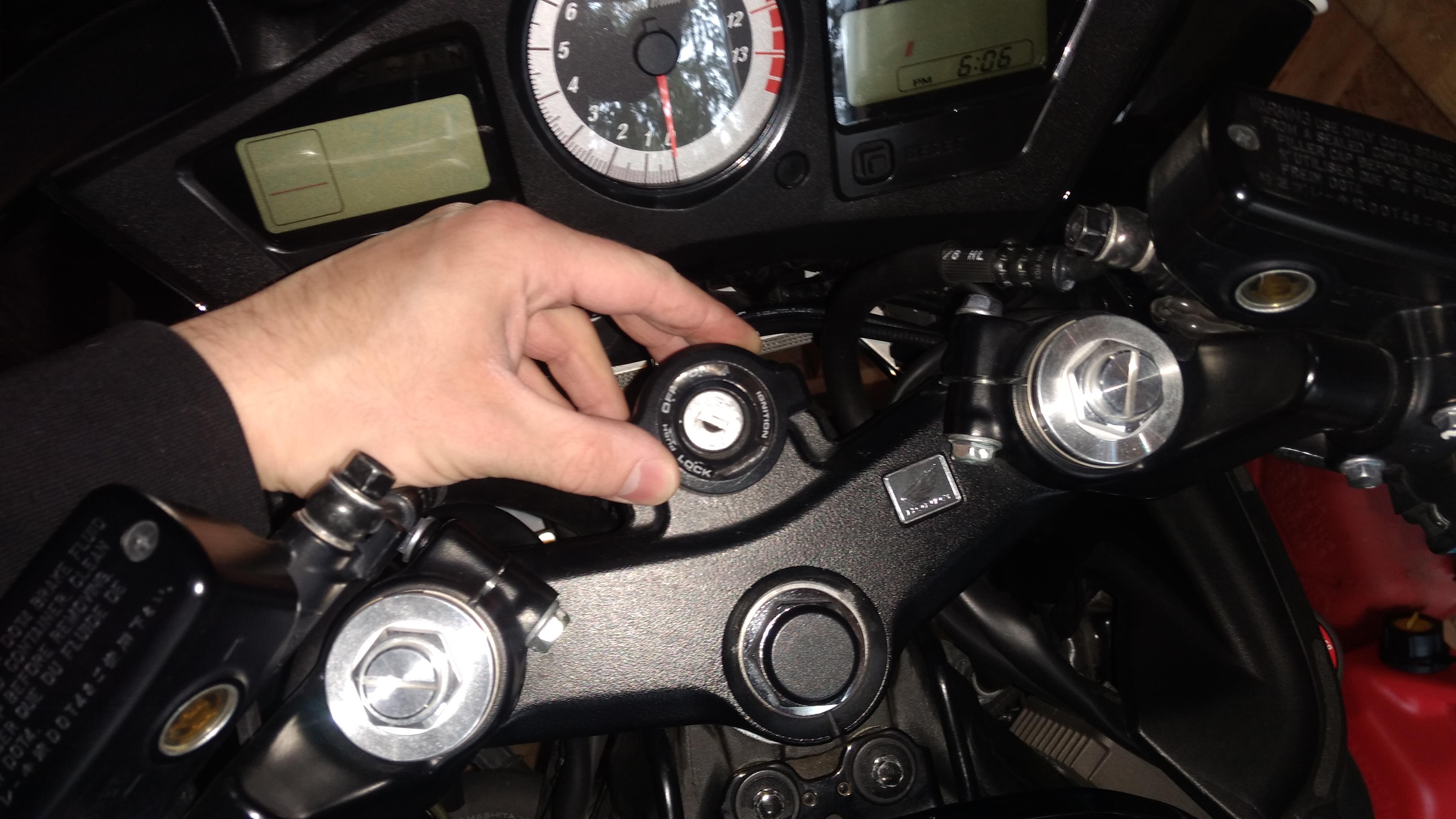
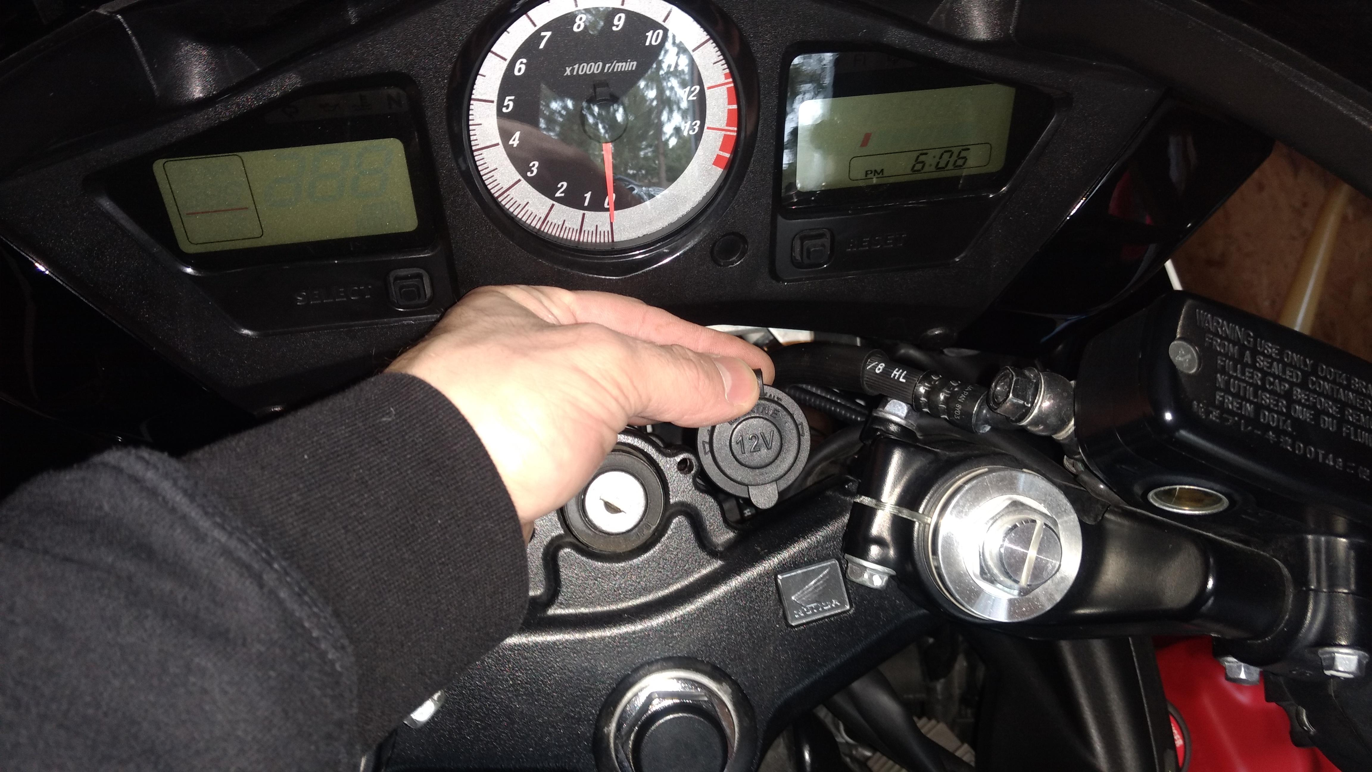
Got another 2.1 amp usb power port from www.3brpowersports.com to install in the left side of the fairing. (dash board) Like the one I installed on the right side which is always hot, this one will be only have power when the ignition switch is turned on via the tail light circuit. At this point I already have the usb port installed in the "dash" and have all the plastics removed for the wiring and relay install. Here I have removed the ecu from it's cover. Makes it easier to maneuver the harness. Pulled (gently) the rear part of the harness out from under the seat support so you can get to the wires much easier. Very carefully slice the electrical tape and remove exposing the wires. The tail light circuit is the brown with blue stripe. The section I opened up you should find some extra amount of that wire. The next few pics shows the installation of a posi-tap and has to be installed in this order. Similar to a piercing valve. No cutting of the original factory wiring I used a brown 16 gauge wire to serve as the power supply that activates the relay. There are instructions that come with kit on how to install the posi-tap. Then tape it up to further prevent moisture getting in. Then tape the harness back up. This is where I put the grounds for the relay and the usb port. The ground wire from the relay is a 12 gauge wire. Nothing wrong with a little overkill on ground wires. While you have this disconnected clean the ground connector and the frame with some emery cloth You will need a lot of zip ties. :) Some you will have to cut off and redo like I did. I also taped over the wires I installed just for added protection. I ran the wire from the tail light circuit under the rear seat support with zip ties. Also run that wire on the bottom side of the rear tail frame rail so it's not in the way of the seat. Perfect spot for a relay. I did have to drill out the hole on the relay mounting tab for the bolt to fit. From the battery I also used a 12 gauge wire. (I may want to ad something else to the relay one day) It is critical that the factory ground tab touches the frame first. All other connections on top. (ground wire from the relay and the ground wire for the usb port) This is the ground wires for the relay and usb port and also the power supply for the usb port all taped and zip tied to the rail. 12 gauge wire going to the relay. This is the power the relay will send to the usb port when the relay is energized. This is the "tap" for connecting a battery tender or heated gear. Location for the fuse to the usb port. Nice and neat. Last pic of the usb port....finished!! There is no noticeable power drain on the tail lights.
-
- 1
-
-
- switched power
- relay
- (and 1 more)