
HispanicSlammer
-
Posts
6,954 -
Joined
-
Last visited
-
Days Won
61
Content Type
Forums
Profiles
Gallery
Blogs
Downloads
Events
Posts posted by HispanicSlammer
-
-
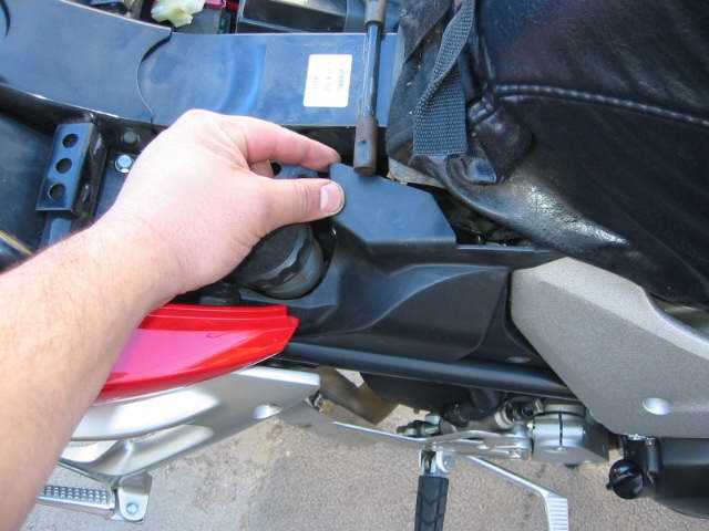
Clutch
This is cake if you just did your brakes! remove the cap to the clutch fluid, suck it out or use a rag.
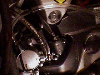
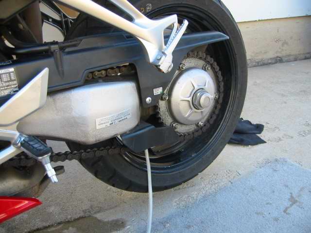
The bleeder bib is on the clutch slave cylinder near the kickstand
 (
(Bleeding a standard VTEC
We began by removing the seat and prepping the back area for work. Take off the 2 black Plastic pieces on both sides of the tank. Actually its not necessary to remove the piece on the right side but It could be a bit of a hassle to deal with.
Removeing the Plastic on the right side
With the plastic removed you have more room to work, push in the center of the plastic clips to remove them.
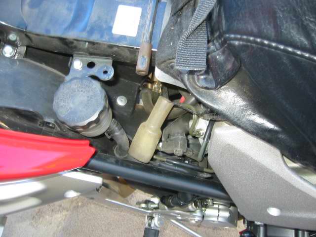
Proportion valve bleeder on the left side
Left side removed covers the proportion valve and battery
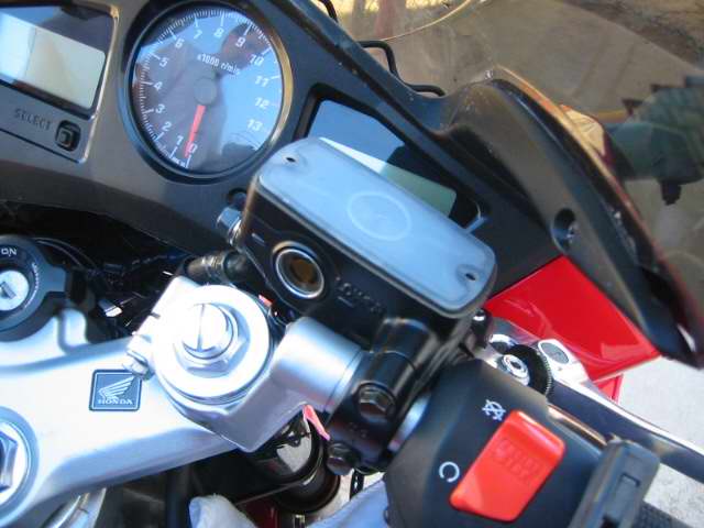
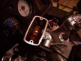
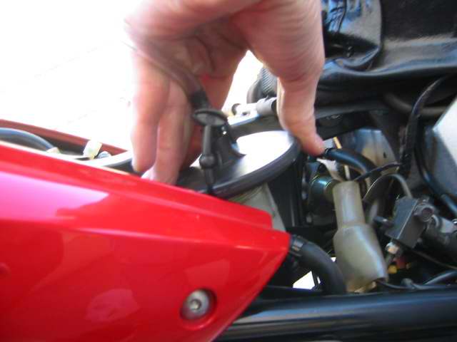
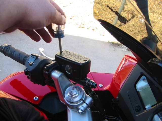
Turn the handlebar to level the master cylinder remove the cap, plate, and diaphram
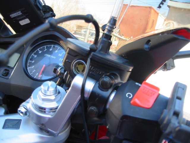
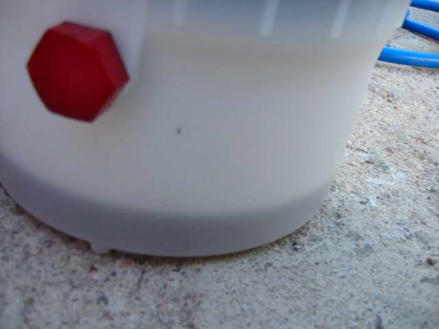
My vacuum bleeder has an auto filler that seals off the master cylinder and siphons in new fluid from a fill bottle.
Begin Bleeding The front Brakes
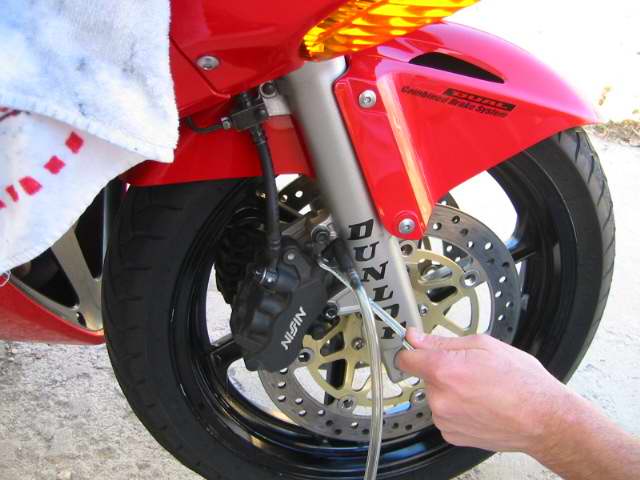
Begin on the right side top bleeder (its the only bleed valve on the right front)
You vacuum until its clean fluid then pump the bar hold it and close the valve. You will get air in the bleeder line its unavoidable, just make sure its clean coming out.
Cruddy fluid still coming out
Now go to the left side and do the top valve.
The bleeders on the calipers are 8mm, after you get clean fluid pump the handle again hold it and close off the bleeder
Top off the master cylinder and your done with the front, put the cap and stuff back on.
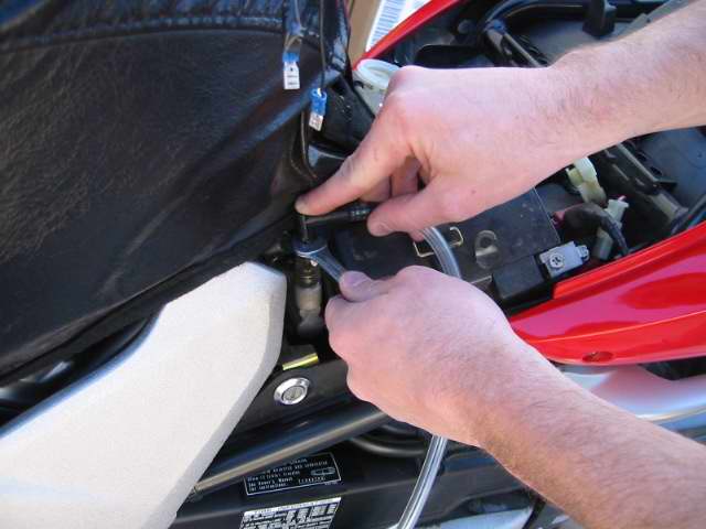
Doing the Back Master Cylinder
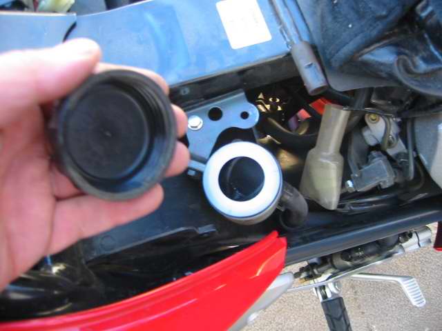
Remove the cap and diaphragm
I suck out the master cylinders first and top off with new fluid before bleeding.
The siphon filler would not seal cause of the ABS plastic was holding it up.
If you spill brake fluid clean it up with soapy water right away or it will eat the paint!
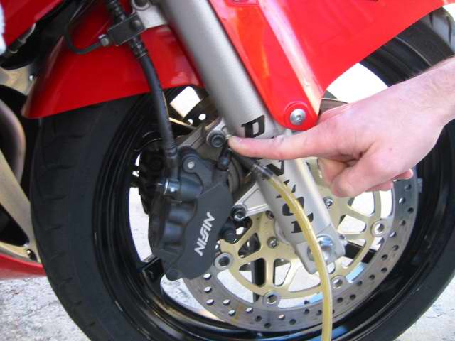
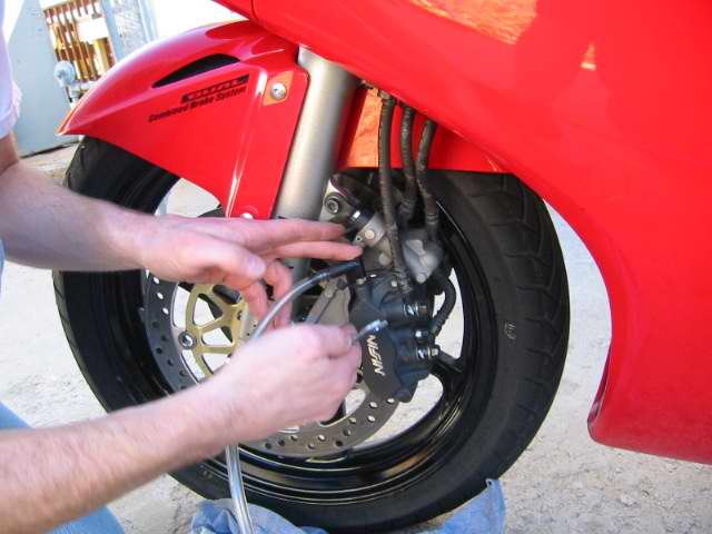
The center valve on the front left caliper is connected to the rear master cylinder start there
They recommend that you remove the caliper and hold it at 45 degrees to help the air bubbles float out, they also say to replace the calipers bolts when you remove them. NAH! Power bleeder!! I just push on the secondary master cylinder above the caliper to pump the air out.
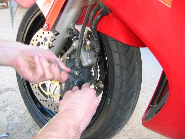
Push on the caliper forward to pump the secondary master cylinder
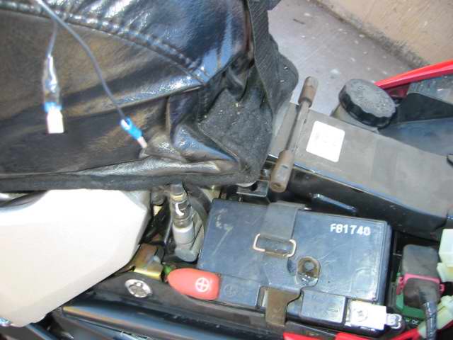
The Proportion valve wont bleed at all until you pump the petal, its 10mm wrench
Top off the rear reservoir so it doesn't go dry, start with the rear top bleeder
The old fluid is very dark! you will use a lot of fluid to do the VFR! almost a liter, we used synthetic Valvoline brake fluid.
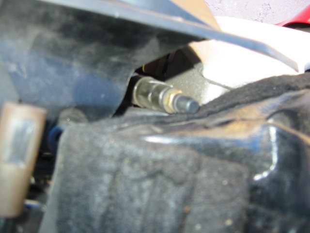
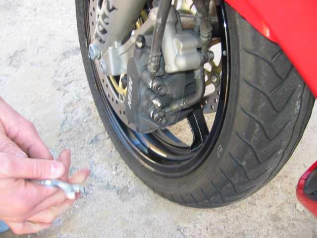
Getting to the valves on the rear caliper is a pain in the butt
you can see a glimpse of the top bleeder in this shot
Again pump the petal hold it and then close the valve, do the front valve after the top valve.
Clutch Line
Remove the cap, suck out the bad fluid, top it off
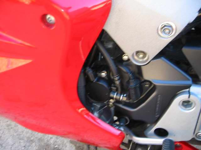
Location of the slave bleeder on the left side of the bike
Check the firmness of the levers and petal and make sure the clutch operates. If you feel spongy then you still have air in the system you will need to re-bleed!
-
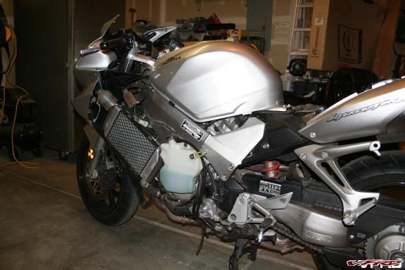
A while back my motorcycle was hit by a large truck in a parking lot. (Some of you might remember the post)
After waiting for the parts and time to do the work, I managed to get it all together to get ready for the riding season here in Colorado.
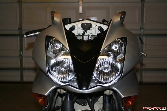
Here is the "how to" on replacing the upper fairing ona VTEC VFR.
mirrors.jpg
remove the mirrors and set them aside. I do it in order to make things easier.
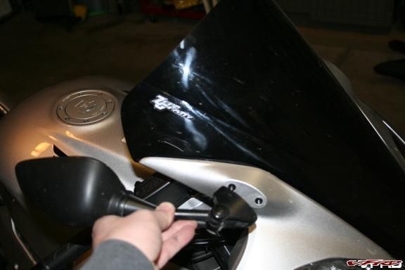
screen cover.jpg
remove the trim covers for the windscreen.
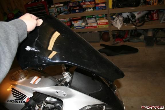
screen.jpg
Then the windscreen itself.
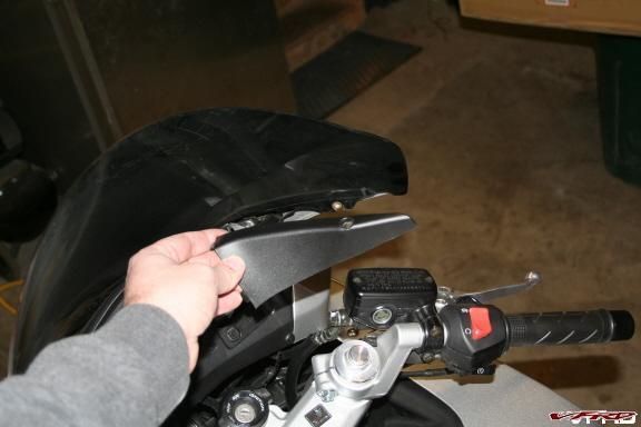
left fairing.jpg
remove the left and right fairings.
bezel clip.jpg
take out the 2 special clips by pushing in the center and then pull them out.
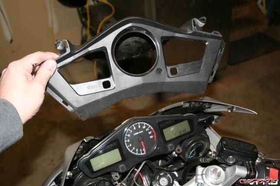
bezel.jpg
remove the bezel by pulling,with medium force on the 2 pins on either side.
bezel trim.jpg
remove the colored trim piece on either side of the bezel as well.
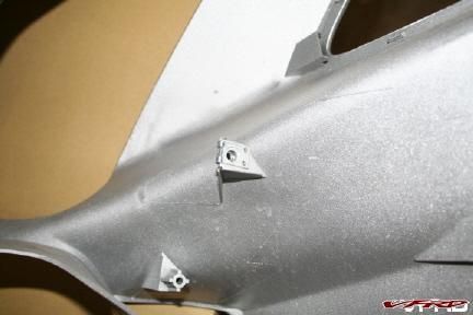
upper fairing 3.jpg
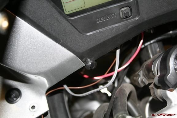
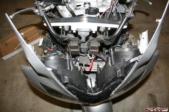
the only thing holding the fairing now is 2, 10mm nuts...remove them and drop the fairing down
upper fairing 2.jpg
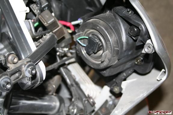
take all light connections off and the temp. sensor.
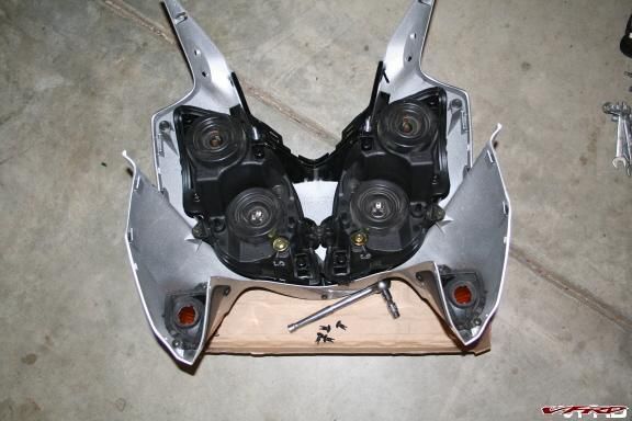
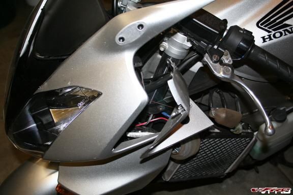
what to replace 1.jpg
While it is removed, take out the light housings (phillips head screws) and the temperature sensor.
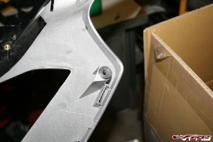
grommet.jpg
don't forget the grommets or
clips 1.jpg
the screw clips to go on the new fairing.
check lights.jpg
install everything back on the new part and connect your lights. Check them before going too far into the install.
Go in reverse order as shown here and put it all together again.
Here is the end result....
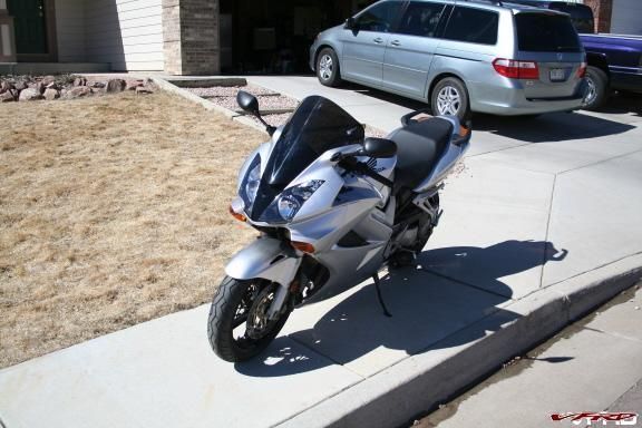
good as new.jpg
Good luck!!
Scott
LDSRIDER
-
Recently I found my self needing to select new brake pads for my bike so I opened the question up to the forum and, as usual, got a lot of interesting supplemental information about extra steps that people take when doing a brake job.
In the thread two post were made which I felt would be particularly helpful to anyone planning a brake job. I have included them here.
Post made by THX1139 on 4/24/07
BRAKE SYSTEM AND ROTOR PREP
IMHO prepping the rotors and maintaining the system has at least as much to do with good brakes as pad choice. When my pads are worn enough to replace, it's time for a caliper rebuild.
Not as big a job as it sounds; and if I don't have a hanging piston and the seals look good I don't buy a rebuild kit. Just carefully pluck the seals/O-rings with a wooden toothpick. Rubber gets cleaned with soap&water, everything else with alcohol.
I polish each of the pistons, mounting them on an expanding rubber mandrel that spins in my drill press. With careful application of some 1500 wet-or-dry they shine like mirrors.
Pistons, O-rings, seals, get reassembled with AGS Sil-Glyde while sliders/pins get synthetic moly caliper grease.
ALWAYS clean my discs with 220 folded in half around the friction ring and wash with acetone. Always hose down pads with brake cleaner, even brand new ones.
Then the master cylinder gets the same clean/polish/Sil-Glyde treatment.
Spending the extra effort really makes for a precise, needle-bearing-like feel at the lever; and so far I haven't felt the need for anything stronger than the stock Honda pads.
________________________________________
The following is a very helpful reference contributed by Gatekeeper on 4/23/07.
From http://www.braketech.com/tech/bedin.html
Racing Brake Pad | Bed-In Procedures
Racing is serious business. Virtually everyone involved with racing spends tremendous time, energy and money in the pursuit of checkered flag. So assuming you want the best from your brakes, please take the time to read and follow these simple procedures:
- For best results, prepare the disc rotors by using a Rotor Hone (BT-RH10.0) or glass-beading the brake swept area. This is particularly important if you are switching from a sintered metal pad as the copper deposition layer burnished into the surface of the rotor can be a barrier to allowing a carbon/metallic pad from bedding-in properly. Maintain your rotors by rotor honing or glass-beading every time you replace your brake pads. On liquid cleaners; Acetone or denatured alcohol on a clean shop towel is recommended, Do not use an aerosol brake cleaner as many leave a residue that promotes brake pad glazing. Take this opportunity to check for fluid leaks. For best performance, we recommend changing your brake fluid every 2-3 events with a premium fluid (more frequently in humid climates).
Please note: DOT 5 Silicone brake fluid is not recommended.
- Heavy braking should be avoided until the new linings are fully seated across the entire mating surface. A visual inspection may be required. Scored discs will require substantially greater bed-in time, reduce overall stopping power and are potentially dangerous. We recommend replacing badly scored or distorted rotors with our advanced composition Ductile Iron or Stainless full-floaters.
- Initially, the brakes should be used lightly (roughly 60-70% of normal) but frequently. As you feel the brakes come in, follow this with progressively harder braking to maximum pressure with momentary cool-down between applications. The goal here is to impart an even transfer film layer from the new friction material to the operating surface of the rotor. Do not try braking hard until they do and you are reasonably certain this is accomplished (usually 3-7 laps).
- If a fall-off in performance is experienced due to heavy braking prior to the new pads being fully bed-in, it is important to allow the brakes to cool down before continuing. A "glazed" surface condition can usually be easily remedied by either utilizing the Rotor Hone or bead-blasting the brake swept area to the remove the burnished deposition layer left by the previous pads. Remove the glazed surface of the pads friction face, reinstall and repeat bed-in procedure.
- CHRONIC GLAZING: Characterized by a very firm brake lever with very poor braking performance regardless how hard the lever is applied. Most motorcycle manufacturers utilize a heat-treated surface hardening process on their stainless steel rotors in an effort to help them survive with sintered metal pads. This sometimes creates a problem with semi-metallic compounds during bed-in. If glazing persists, glass beading of the brake swept area can eliminate the problem by thoroughly cleaning the surface and attenuating the heat-treatment with a more compatible shot-peened version. As a reminder, it is always a requirement to thoroughly clean the rotors with Acetone or denatured alcohol after using a rotor hone or bead-blasting. Reinstall de-glazed pads and allow 1-2 laps to bring up to operating temperature, the results should be most satisfying.
SAFETY INSTRUCTIONS
Although all modern Ferodo Ltd friction formulations are non-asbestos, it is prudent and recommended to take adequate precautions while working with any manufacturers friction materials. Please observe the following:
- Operate in a well ventilated area and avoid creating dust.
- Machining (not required in proper application) should only be carried out using approved dust extraction equipment.
- When fitting brake components, use appropriate dust extraction equipment or a damp cloth to remove dust.
- Do not use an air hose or brush to remove dust.
- Dampen dust, place it in a properly closed receptacle and dispose of safely.
________________________________________
Just as an FYI, I found the Braketech web site tech area to have a lot of valuable, additional information about this. Their URL is, http://www.braketech.com/tech.html
I hope that this reference page is helpful.
Best,
Dan
- For best results, prepare the disc rotors by using a Rotor Hone (BT-RH10.0) or glass-beading the brake swept area. This is particularly important if you are switching from a sintered metal pad as the copper deposition layer burnished into the surface of the rotor can be a barrier to allowing a carbon/metallic pad from bedding-in properly. Maintain your rotors by rotor honing or glass-beading every time you replace your brake pads. On liquid cleaners; Acetone or denatured alcohol on a clean shop towel is recommended, Do not use an aerosol brake cleaner as many leave a residue that promotes brake pad glazing. Take this opportunity to check for fluid leaks. For best performance, we recommend changing your brake fluid every 2-3 events with a premium fluid (more frequently in humid climates).
-
I just removed the stickers from my VFR. I've removed stickers before but never motorcycle stickers. These stickers have some real serious glue under them. In the process of figuring it out I tried a few different methods that had worked for me in the past but only one really worked. My guess is that if you've never removed motorcycle stickers before you could waste a good deal of time figuring it out (like I did) so I decided to write a How-To on it. (These steps are for the large stickers. Once these are done the smaller ones on the nose and tail will seem like a cake walk.)
The short steps;
1. Cover floor.
2. Remove side sticker A.
3. Mask below sticker A.
4. Spray Goo-Gone and allow it to soak in.
5. Remove side sticker B.
6. Mask below sticker B.
7. Spray Goo-Gone and allow to soak in.
8. Return to side A and remove sticker glue w. credit card.
9. Do the same for side B.
10. Wax and polish side A and B.
The expanded steps;
The way I did it was with a blow drier, some Goo-Gone, painters tape, a credit card, a clean rag, newspaper and auto wax.
To remove the stickers I used the blow drier to soften them up and separate them from the glue backing. They came right off. Note this!... It's easier to remove the stickers from the end of the words back. Pull the lower descender of the "R" in "VFR" back to where it meets with the rounded part of the "R." Next, do the rounded part of the "R" to the same point. Finally, work the entire sticker from the end of it to the beginning. If you take your time and use the right amount of heat you should be able to remove the entire sticker (without tearing it) with one long pull.
Once the sticker is off the work starts. The glue is dark and kind of hard. It's also quite impermeable. First, put some newspaper down under your bike. Since Goo-Gone can leave a mild haze I decided to mask off below the sticker and drape a piece of plastic off the part of the fairing below the sticker prior to spraying so as to prevent run-off on to the paint. Both of these tips will make cleanup a lot easier.
Spray the Goo-Gone on it and allow it to soak in. Spray enough so as to see it setting on top of the sticker. The Goo-Gone should sit on there for around 10 minutes. It will minimize the elbow grease you'll need but not eliminate it. You can go start the other sticker while it's soaking.
After the soak time it's time to go at it with your credit card. I put a slight bend in the card and basically wiped away the Goo-Gone and glue in long, narrow strips starting at one end of the top of the glue spot and going all the way to the other end. Start working from across the top and work your way down. It makes for less mess and allows any excess Goo-Gone to move down to the areas of the glue that you are about to remove. As you're doing it don't get too carried away with perfection. You'll be able to go back and wipe away any spots you missed as you clean up. Also, there is a certain angle and bend to hold the card. It's hard to describe but you'll have plenty of time to figure it out and when you do you'll know it. You'll just be able to remove a lot of glue in one long swipe.
As you remove your stripes of glue take the time to spray extra Goo-Gone on it. Every now and then you'll want to wipe the credit card clean, too.
Once you're done give the entire area a good, cleansing wipe to make sure that you're clean of all glue. Next, do the other side.
Your last step should be to wax and polish the areas to eliminate any potential for haze left from the Goo-Gone and to be absolutely sure that all of the glue is gone.
I hope this helps. :)
Best,
Dan
-
Crime in Canada? No!
-
After 27 K miles, I decided it was time to replace my chain (hey, good cleanings and lots of lube). ?So WITHOUT having the fancy chain breaker / flaring tool, I forged on knowing with a bit of creativity I could do the job. ?I shagged a chain / sprocket kit last Christmas and now I was going put it into use.
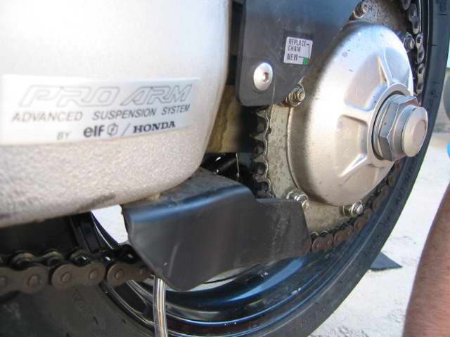
I removed the rear wheel and the side plate that holds the clutch actuator and the speed sensor pick up unit. ?There are 4 ? 8MM bolts holding the plate on with two the same length and the other two shorter. ?One by just a little bit and the other by a lot. ?Remember which is which so the unit goes back on easily.

With the plate off I noticed the bike had grown a lot of hair so it needed a shave. ?I fired up my can of Burma Shave and lathered it up. ?Or was that engine degreaser to get rid of all of the gunk that collected in there from all that chain lube. ?Hosing off the junk gunk gave me a clean area to work on.

Break loose both the front and rear sprocket holding nuts with the bike in gear before taking off the old chain. ?That makes the job easier.
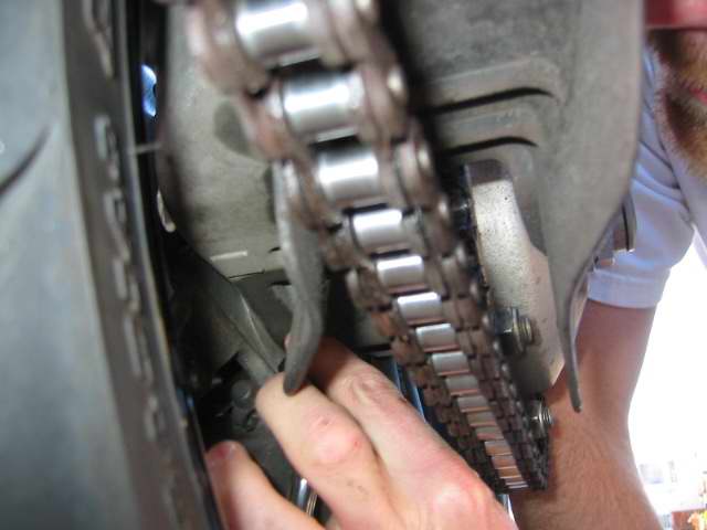
Here is a picture of my two chain breakers. ?I used the big red one but the smaller one would work fine also. ?Move the chain adjuster on the rear hub as far forward as it will go so the new chain diesn't fight you going on.
I greased up the teeth on the front sprocket driving shaft before putting on the front sprocket. The new chain was threaded in place and the new master link was ready for installation.

Put two ?O? rings on first and then grease the master link pins as well as the holes in the new chain?s links they will be going into. ?Then install it and put two more ?O? rings on the pins once the master link is in place.
I measured the chain?s width at across a number of side plates with a dial caliper and came up with an average figure of .890 inch. ?That is how far I wanted to press the new side plate on to the pins and no futher.
I thought about a variety of ?pressing tools? that included ?C? clamps, pipe clamps, a mini-vise but ultimately settled on a large pair of curved jaw vise grips. ?I feel that a good wood pipe clamp (that is used to clamp sections of wood together) would work as well as the vise grips but you would have to use a template to fit the width of ?the link you are working with so the wider jaws wouldn?t contact the neighbor links.

The side plate started on nicely but you could only go to the point where the pins get to the far end of the side plate until the vise grip jaws interfere with pressing it on any further. ?At that point I took a piece of steel I had, drilled holes in it that matched the holes in the side plate but larger and continued pressing the plate on the pins by being sure the vise grips were parallel and turning them no more than ? turn tighter each squeeze.

I proceeded very slowly and took measurements as the plate was squeezed on. ?When I got to .890 I stopped. ?Now the plate was on the same distance as the others.
The next hurtle was to come up with a means of flaring the pins.
I took a ? inch bolt and ground the end off at about a 60 degree angle and cut it off to about 3/8 inch long.

The angled end was placed in the end of the master link pin and the vise grips were put back to use to squeeze the fabricated tip into the pin. ?I was always careful to be sure the opposite end of the vise grips were contacting the far end of the pin only and not the opposite side plate while doing any squeezing. ?This process started the flare at the end of the pin that would insure the side plate stayed in place. ?I then traded the angled bolt for a ball bearing which further flared the pin.

The flare doesn?t have to be huge. ?Just enough to stop the side plate from moving from the position you set it in. ?The plate itself is a very tight machine fit and it doesn?t take much at all to keep it in place.
The clutch side plate was then put back into position.
The speed sensor pick up looks like a 6 point socket that fits over the front sprocket securing nut and spins along with that nut. ?I noticed the nut didn?t seat into it as far as I would like it to so I took the clutch side plate back off, removed the sprocket nut and added another washer to the sprocket nut to set it out a bit further so it would sit in the sensor a bit deeper. ?Probably not necessary but it just made me feel better.
Everything was re-composed, all bolts torqued to spec, the chain was adjusted and off I rode into the sunset. ?It was like riding a new bike.
-
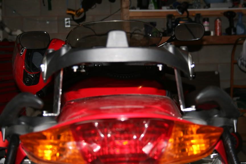
I've hooked up with a steel fabricator/manufacturer that will make me up some sets of the Top box brackets that I have on my 02.
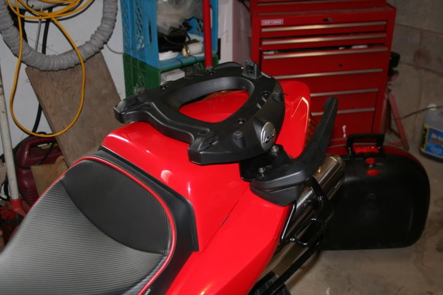
For now - there is a "prototype" set made that I have yet to look at, but I'm sure the quality is excellent. These brackets fit on top of the grab handles on a 6th Gen, and allow you to mount a GIVI type base plate to it - and then the topbox that mounts to the base.
The brackets allow the seat and cowl to be removed without having to take the brackets off - access to tool kit, battery - etc - is unaffected.
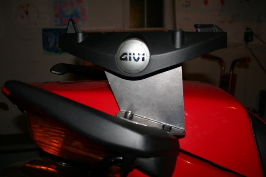
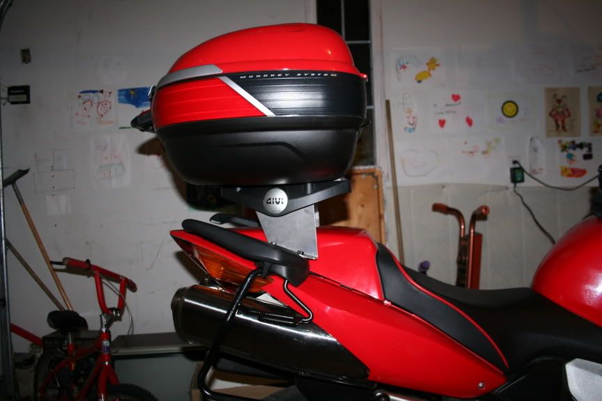
Looks something like this:
The benefit of this set up is that the weight of the topbox and contents is now repositioned above the pillion seat - versus hanging out back with the standard rack setup. The downside to this bracket set up is that you lose the pillion seat. For me it isn't an issue.
Here's a couple shots of the raw brackets from my mod of last year. These brackets were not yet cleaned up and painted. The ones I'm having made will be painted gloss black, or will be powder coated - not sure of the cost on powder coating.
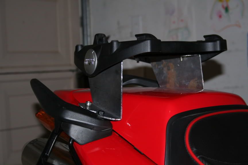
I'm trying to gauge interest so I can plan on how many sets to build. The brackets will not have drill holes for the base plates - as I do not want to "commit" that every user will have a GIVI system. This shouldn't be a problem, as it is simply a matter of attaching the brackets, laying the base plate on the brackets, marking the holes and then drilling them.
Price is $83.00 USD including shipping in Canada or the USA. Other countries I'll be happy to get you actual shipping prices. (Base price for the brackets is $75.00USD - but to make it simple I added in $8.00 for shipping).
IF you are interested in a set, please let me know. I have heard from two members in the last two days that want a set, so I thought I'd post this up for any others.
Thanks!
Ken
SEE THE FULL THREAD AND FINISHED PRODUCT AT :
-
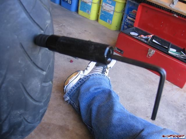
This is the thing we all dread, FLAT TIRE, 1000 miles from home, its starting to get dark, the cell phone has NO BARS, and you haven't seen a car pass by in a half an hour! What do you do? You break out the tools!

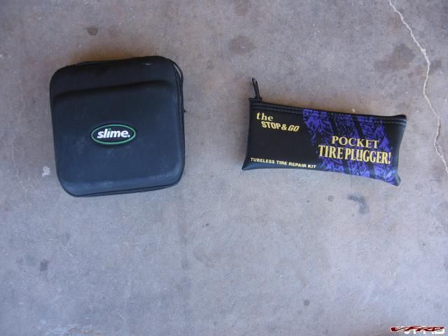
Stop and Go Repair Kit Slime Compressor
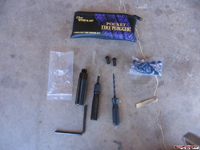
Various Parts Rasp/Reamer, mushroom plugs, Nozzle, Needle tool, press tool, blade, Hex wrench - YOU WILL NEED TO PACK A PLIER AS WELL!
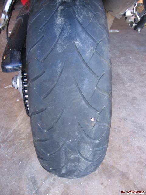
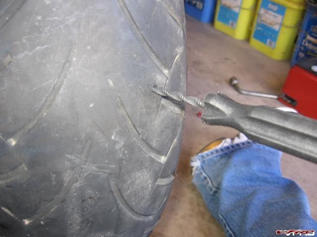
Dunlop 220 with nail in it No Michelin's were harmed by this demonstration!
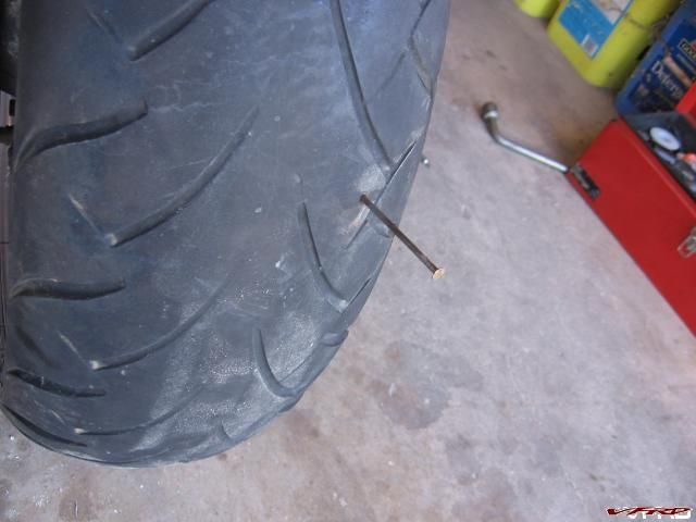
Remove Nail with pliers This could be tricky if you don't stock a plier or a multi tool
Insert the rasp ream out the hole by twisting the rasp and enlarge the hole wide enough to insert the nozzle
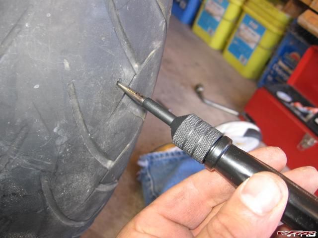
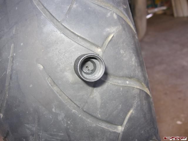
Insert the Nozzle using the supplied needle tool
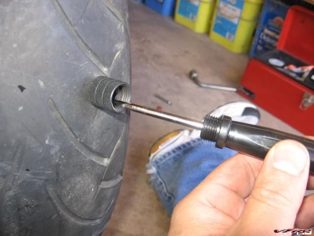
Leave Nozzle embedded into tire unscrew the needle tool and remove it from the nozzle
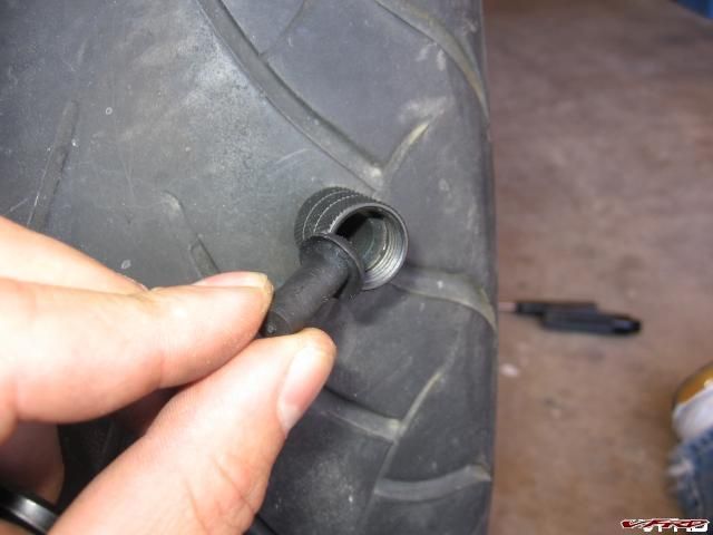
Insert mushroom plug into nozzle I found it is easier to put the plug in by hand rather than loading it into the plunger tool.
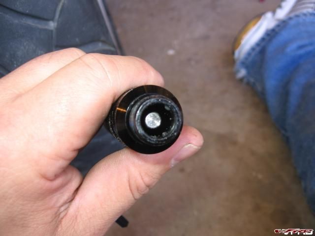
Business end of plunger tool there is a shaft that screws in and out from the inside using a hex wrench
Screw the plunger into the nozzle make sure the plunger is backed out first - screw the plunger onto the nozzle - tighten down on the plunger using the hex wrench till the mushroom plug is pushed into the tire through the nozzle then back out the hex wrench and remove the plunger tool nozzle and all
Demonstration you can see the mushroom plug pushed in as far as it will go, screw on the plunger again and remove the nozzle from the tire
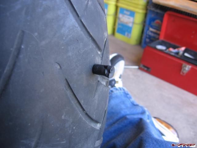
Seat the plug you will need pliers to pull on the plug till it is stretched 2 inches to seat the mushroom head inside the tire.
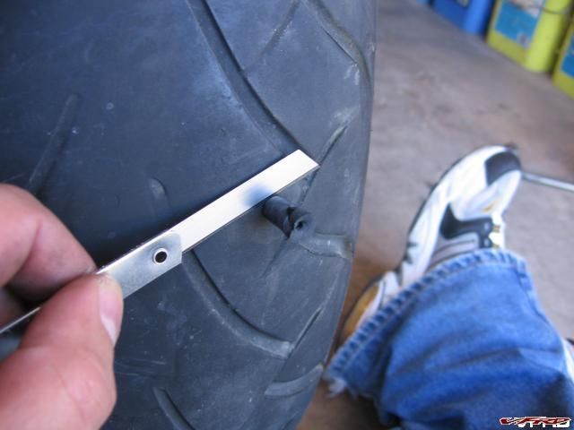
Trim the plug do not pull on the plug while trimming leave it slightly long - not flush it will wear off with use.
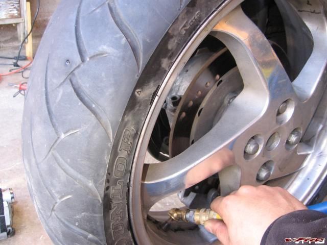
Inflate the tire
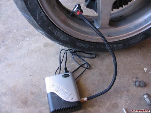
Testing the Slime compressor it would take about 15 min to inflate a rear tire using the bike to power the compressor - turn the engine on so you don't drain the battery.
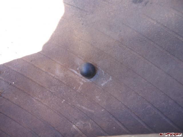
Mushroom plug as seen from the inside of the tire
Stop and go claims you can repair holes up to 7mm and that the plugs do not require glue, I will pack some glue anyways just for added measure. It is important to seat the plug as I did not do that (read the directions Miguel :rolleyes: ) the plug either popped out a bit while I was taking the tire off or it did not seat it properly in the first place. Stop and Go does not recommend more than a 100 miles on a repaired tire and speeds no greater than 50mph! Till you can have the tire replaced or patched with a permanent patch.
-
I would pin this but there are too many open questions on exactly how you did it, and there are quesitons as to why you bypassed the main bus fuse? If you could perhaps draw and scan in a diagram or use ms paint? or take some digital photos of how you did it so we can plainly see whats involved - pics solve a lot of questions that are difficult to explain.
there is a great how to in the maint section > how to guides on how to perform a linemans soldier splice its easy to perform, is secure and does a good job of making a solid connection.
-
i am confused? (again!) i have a y2k and removing the seat has nothing to do with these bolts. when i commute with the bike i use these bolts to tie on my lunch box (six pack cooler(got to have good lunch)). i fail to see any benefit (but i'm married so what do i know!)
i have noticed that in hs how-tos the pic are always excellant however; the most trick thing here is in the finished project photo has a shadow photographer :thumbsup:
If your rear cowl is on - frankenbolts included - go right ahead and try to remove the seat without removing the frankenbolts?! Unless you have a 6th gen? You have to take off the rear cowl to take off the seat, which means remove the frakenbolts. Not a big deal if your not needing to get under the seat all the time. Frankenbolts require you to carry a hex key or a flat head somewhere (not under the seat with the toolbag)! For me it was just easier to do the mod, after having lost a frankenbolt on the road, after not torquing it enough with my crappy flat head screw driver in my tankbag.
-
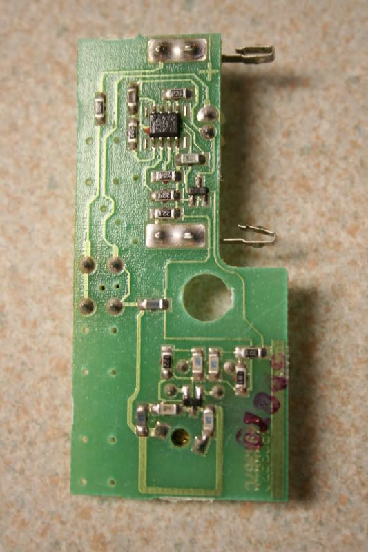
Ok - so I ripped my spare transmitter apart.
It has a micro switch that is soldered with four pins. Can someone tell me based on these photos - where I have to wire the leads in from the appropriate leads on the relay? I plan to use a standard relay like that used on the Stebel horn mod.
MIcroswitch:
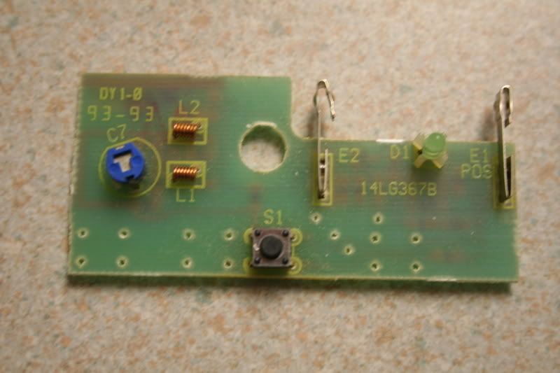
Other side:
THanks!!
Well it looks like to me from the backside that the top two and the bottom two leads of the switch are bridged, just looking at the printed circuit on the board. You can just pop off the switch with an iron, stick lead wires in either of top or bottom - using one wire in the top set one wire in the bottom set. Basically its two wires with 4 holes - 2 holes for each printed wire. its a redundant switch the way they designed it, probably cause its a bulk switch or it mounts better using 4 soldier joints instead of just two. If your really an anal kind of guy you can take off the led and mount it remotely as well! HEH planting seeds here!
-
1000miles seems a bit too early I usually go a month or 3k just not cost effective and 3k oil pretty much standard thinking for high reving bikes, 5k being a safe upper limit. I can rack up 3k in one trip seems like with all these great vfrd adventures I like to do. change tires change oil is about right for me.
-
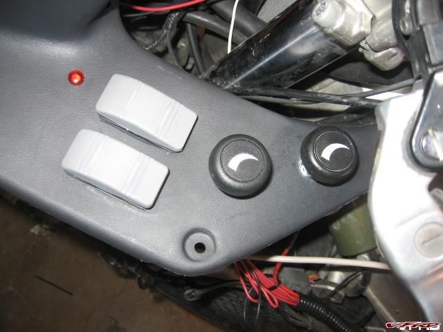
Blue Sea switches and hot grips controllers
After two years of my previous wiring effort, my el cheapo fuse block - aka checker autoparts special corroded and fell apart, leaving half of the block powerless. Perhaps it was the placement of the unit that caused it, probably I had it up front by the left radiator! So I decided to replace it with a better block and put in some new switches to boot.
Anybody who knows me or has seen my bike knows it built for long distance touring, with heated grips, heated seat, and heated vest! What can I say I don't like getting caught in the cold - out here in Colorado it gets cold at a moments notice! Surprising cold like my trip to Montana last summer where it was down to 35 degrees on the Black Foot Indian Reservation, my heated stuff really came to my rescue! That comes with a price though, a burned out stator for example. So my solution is to remove a head light from the equation! Thats 55 watts for me! So I put the right bulb on a switch so I can shut it off at will - like an RC51 headlight! That frees up some much needed watts when it gets cold! I cant count how many times I have been hundreds or thousands of miles away from home in the cold and alone!
NOW TO THE REWIRE!
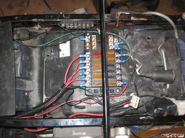
Blue Sea fuse block with built in ground block
I bought the big fuse block cause I have a ton of stuff wired
- radar detector - el cheapo scorpion target special
- heated grips - dual stars
-
heated seat - do it yourself with kimpex element
- heated vest - widder (soon to sell for aerostich bladder)
-
signal dynamics voltmeter - heads up single led display
- relay trip power - for my headlamp wiring job
- cigg adapter seat - for my camera gear
- cigg adapter fairing - for compressor
lots of crap, which are used sparingly at best, except when its cold to the bone when I am using the heated stuff allot! I positioned the block under the bar so I can't use the lid, that way I can fit my tool roll, my tire patch kit, and my compressor under the seat.
Blue Sea switches and hot grips controllers
The switches are double throw, on the right I have my the headlamp off switch down, and the manual fan bypass (turn it on at will) up. The right switch if for my dual burning headlight mod for the 5th gen, turns on hi and low at the same time for extra light when needed!
The nob's are hot grips pulse width controllers for the seat and my vest! I had them on a single controller but the seat would be too hot and the vest too cold so I put in a second one and separated the circuits.
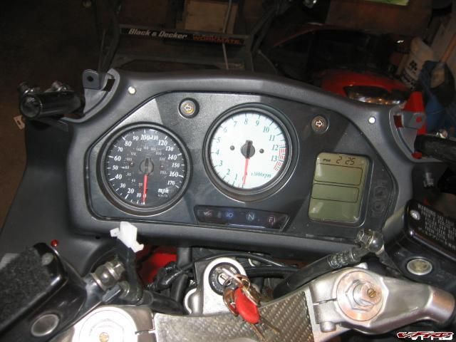
Signal Dynamics Heads Up Display LED up voltage display and multi color indicator led for heated grips which I custom made from a multi lead LED two resistors, two heavy duty diodes, and wired it to my headed grip wires. It burns green for low, and red for hot.
Stealth position for Radar Detector for when radar detectors can get you a ticket.
I have to give credit to Dutchinterceptor for this idea, he has his Valentine one in a similar position, I took my el cheapo target special (scorpion) detector apart hit it with a soldiering iron to remove the laser sensor and wired up an extension wire, put a switch on the right hand side to turn the detector on and off, wired up a lead to the remote speaker, which I have routed into a passive mixer (listen for radar beeps and my ipod at the same time) I found out that in Amarillo Texas its illegal to have a radar detector so I put it in a hidden spot behind the fairing, sure its blocked but radar can go right through the fairing no problem, its mounted sideways but I tested it on one of those city speed signs with a radar that tells you your speed! It works. It never was a top tier detector anyways.
Removed Laser sensor and rewired to face forward removed and hardwired laser sensor to face forward out from behind the fairing.
I found an LED casing that I can glue it into for added protection later, I just wanted the laser sensor to be able to work unhindered by the fairing.
BLING!
Eagle Eye II 1157 led bulb replacements
I am always burning out standard taillights so I found these led units on the web Link, they are supposed to be the most powerful led bulb you can get, and they have an enormous heat sink on them, and wiring inside to handle the voltage. They are just pop in replacements. Hopefully these will last! I had to rewire the leads cause they corroded and were hanging by a single thread of wire, one had come apart completely, so I popped the connectors off and soldiered in new wires. I need to replace the connectors but now it works! 5th gen brake lights have a tendency to work loose and burn out, I tried to remedy the situation by wrapping electrical tape around the mounting posts to make it fit snug so it wont rattle , then rewired the connectors, replaced with sturdy LEDs bulbs - I hope I don't have another rider come up to me yet and again to tell me that my tail light is out - AGAIN!
Scott Oil Filter Reusable micro screen filter & magnetic oil plug.
I also changed my oil and installed the Scott filter I ordered months ago, its a spring loaded unit with a billet machined body, a 35 micron stainless steel filter good up to 600 degrees! And it also has a built in rare earth magnet on the front of the filter to attract metal filings from crankshafts or whatever magnetic stuff would be floating around in the oil, (cam shaft lobes, crankcase bearings etc) - also installed a blue anodized magnetic oil plug, its a dirt bike plug but it fits just right! smaller bolt head thats 12 mm instead of 17mm, it torqued up fine.
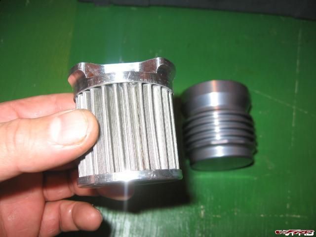
Stainless steel filter material 35 microns superior flow
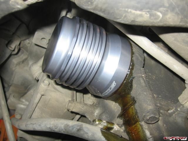
Installed Scott includes a filter wrench that fits over the machined filter body
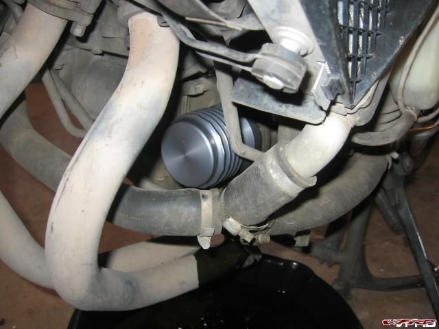
looks nice the rest of the bike looks not so nice!
- radar detector - el cheapo scorpion target special
-
Sounds to me like a faulty temperature sensor, Intake Air Temperature sensor or the Coolant Temperature Sensor. Most likely the coolant temp sensor since its is what measures the engine temp, and thats when your having surging issues at temp.
You should check for ecm codes - 7 blinks indicates off spec for the ETC sesor. Then measure the resistance between the yellow/blue (+) wire and the green/orange (-) wire terminals it should be 2.3-2.6 ohms at room temp (68f), then you need a harness to measure its output voltage - probably best done at a dealer who has the tool. It should be 4.75 - 5.25 volts. Unless you can rig up a way to test the voltage by piggybacking at the ECT connector or somthing.
-
Keith you have to push on the bottom of the compression valve, push it inside into the cartridge in order to get at the circlip iholding it in, once thats out you can remove the compression valve, careful that circlip will want to bound out of there and take off then dissapear in the dark reaches of your work area!
-
Well to be sure the color is not the problem, mine had a ground short in one of the phases, definitly melted a wire to the stator body!
-
yea yours looks as bad as mine did, mine would rear its ugly head when it heated up! melted or exposed wingings just expand or become so resistant at temp that they no longer function when they get hot! However once cooled operate well enough to fool a test!
-
I am more concerned with the voltage dropping from idle to 5k rpm! That would indicate a bad RR! If you really concerend about the Stator take the thing out of the engine case and inspect it, I had one fail - deep fried it! My engine overheated once cause the fan wasnt working, that contributed to the stator failure. Mine was pretty bad!
-
Cool stuff HS, I was playing with this on my F4i a little, but gave up for now. I was cutting off the tight wound end of the spring, I guess that was wrong! :unsure:
That depends - see above two posts, might have made the best spring of all!
-
Larger pitch means higher spring rate.
Here is another missunderstanding. Spring rate is constant and has little to do with the pitch angle of the spring!
Spring RATE is determined by the number of coils, the diameter of the wire, and the mean diameter of the coil (center to center looking top down) not the pitch.
Meaning the pitch angle or distance of the coils together does not effect the rate of the spring per sae - UNTILL they bind! In a dual rate spring such as the vfr the closer wound springs will bind first - they simply have a shorter distance to travel before binding - once a spring binds the number of effective coils is reduced by the number of coils touching each other! So the close wound springs at the bottom of the fork will bind before the longer wound springs and be removed from the number of effective coils increasing the spring rate at that point....
Pitch does effect Spring LOAD - which is determined by how much load a spring can support at a given height. The rate only tells how much height will change as load is changed. A spring can lose its load height over time if steel is not heat treated properly. When a spring sags, its rate is still the same as when it was new.
In example a VFR spring has 6 closely wound springs and 20 longer wound springs. The total free length of the spring is 375mm, the free length of the close wound coils is 50mm. 6 x .5mm = 30mm, you have 20mm of spring travel before you lose 6 effective coils then the spring rate is increased because you have less coils now in the spring - that is to say once the short wound coils bind it is no longer part of the effective spring. That is how you get a dual rate spring, the shorter coils bind and you get fewer coils from that point on with a new higher rate. Here is the forumla
G * WD4 / 8 * N * MD3 = Spring rate lbs/in
G = Torsional Modulus for Steel = 11250000
WD = Wire Diameter in Inches
N = Number of Active Coils
MD = Mean Coil Diameter in Inches. Mean Diameter is: Looking top down center to center
I.D. = 1 Wire plus inside Diameter
O.D. = 1 Wire minus outside Diameter
8 = A Constant for all Coil Springs
Calculating the spring rate for a vfr spring at no compression and after 20mm of compression
26 coils at total free length
G = 11250000
WD = .19 in
N = 26 coils
MD = 1.2 in
lb/in divided by 56 = kg/mm
spring rate = 40.79 lb/in or 73 kg/mm
now with N = 20 coils after compressing the spring 20mm (all 6 of the short coils binded)
spring rate = 53.03 lb/in or .95 kb/mm after 20mm of spring compression!
the attacment file in the first post is the updated excell worksheet with the above formula
-
Won't the spring bind up at some point.
Don't heavery springs have thinker wire and/or more coils?
Either way the write up is pretty cool. Somebody has been doing there math homework.
Well yea! we calculated that to be 130mm for a stock spring! Its just the thickness of the wire diameter times the number of coils - easy!
.5mm * 26 coils = 130mm
If you cut off 4 coils as in the exorcise to increase the spring rate you get
.5mm * 22 coils = 110mm binding length.
I found a better formula for calculating spring rates - you can only increase a springs rate by a finite amount till you run out of coils, or fork travel.
-
I think Mark refers to Dynamic sag as Static sag - Dynamic meaning the bike with the rider on top, static no rider. Think about it Dynamic is power, moving Static means not moving. Riders are Dynamic!
-
Measuring coil length on the short side of the spring
Let me begin by addressing a few items first as to why post this in the first place. One reason is to do what I always do, (being the cheap bastid I am) - why spend good money on a spring you can make yourself for a fraction of the cost! Assuming of course you need a stiffer spring! You know you do because you changed your fork oil, its spring like weather outside and it is warm, you set your sag to 1/4 - 1/3 of the total fork travel to the optimum sag for a vfr (I split the difference) and of cours to answer the question below!
Howdy,I finally sent my forks in to Aftershocks. They've told me a few things that I'm having trouble understanding and thought to get forum advice.
1. Rather than putting in new springs, they can modify the progressive springs I'm currently using (by cutting off the "progressive" section) and this will give the same desired end result.
($50 to cut off part of old spring vs $110 to put in new springs)
2. Age of the spring does not matter, springs actually get better with age (my current set of progressive springs have something like 17k miles on them. My old stock springs have ~25k miles on them)
3. Stock springs are typically better than aftermarket springs b/c the stock springs are "heat-wound" (or something like that) while most aftermarket springs are not.
4. Cutting off coils on the stock spring (~0.74?) can somehow modify them to a 0.95 spring rate and this will somehow be better than using new aftermarket springs that are speced at 0.95.
How can cutting coils get a better spring rate? Wouldn't this mean they would cut the coils and put spacers in? Wouldn't this reduce my fork travel? If springs get "better" with age (assuming better means consistently maintaining their spring rate), then why do I need to crank my pre-load tighter and tighter as they age?
So, if anyone has had their springs modified and can attest to successful results, I'd love to hear about it.
Cheers,
Zohar
Los Angeles
98 VFR
06 Triumph S3
total for travel 120 mm / 3.5 = 35mm
Wow so you checked it like I show you here and you end up screwing the preload all the way too the top! Something is wrong here! I guess your too darned fat for the vfr :blink: heh just like me! What do you do ? You have kids to feed! ~ and a wife who needs money for groceries! Here is what you do, you cut the stock springs down to size - thats what! You will need some tools but your a guy and guys have tools right! (well so do women who ride)
Now how do you figure out what the spring rate really is? You can look it up in your shop manual, according to everybody at vfrd your springs should be rated at 0.74 kg/mm! There is a simple way to measure it yourself! Vfr springs are steel! Go get your wifes bathroom scale, without pissing her off about it - or buy your own! And put it on the floor, clean up the fork spring first (not oily or rusty!) and get a tool you can push down on it with and keep it in line, like a shaft of a large screw driver! Thats how I did it!
First measure the total free length of the spring!
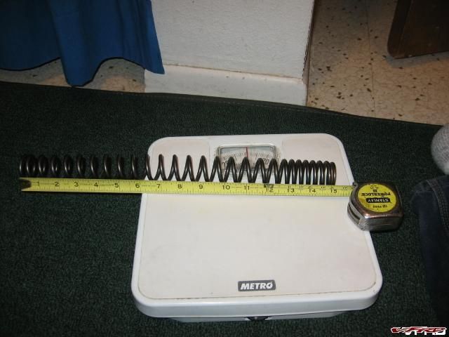
Measuring the Spring Free Length Amazing its exactly 15 inches pretty darned close anyway.
You would think they got them from the USA?
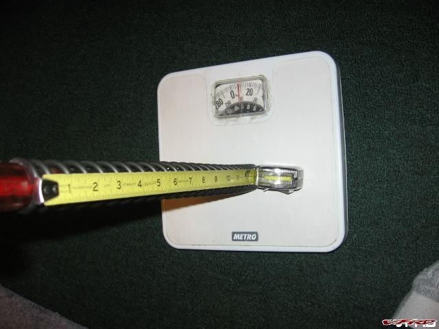
Pushing down on the spring using a large screwdriver I stop at 10 lbs tape now reads 14 3/4 inches or so
I use this as my baseline measurement and then I push down on it more to add more weight to the scale!
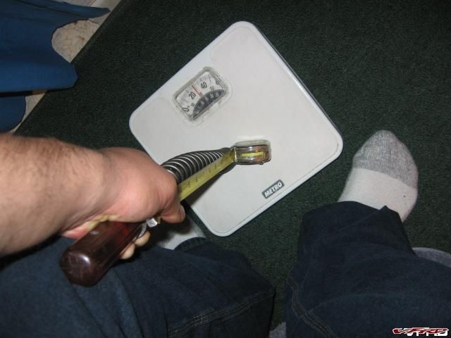
Pushing down on the spring more I pushed on the spring till the tape moved 1 inch from the free length reading 14 inches
It was a difficult to take a picture and do all this so I just took the photo to demonstrate then did the actual measurement after I put the camera down, the spring will want to twist up on you which is why you need a long shaft to hold it. I ended up pushing in the spring one inch and getting the scale to read 40 lbs!
Take the difference in weight
40 minus 10 = 30 lbs
Take the difference in length
14.74 minus 14 = 0.74 inches
OK simple calculation gives you the spring rate in empirical scale
30.0 divided by 0.74 = 40.54 lbs/in spring rate
convert that to metric using conversion constant (looked up on the internet)
40.54 divided by 56 = 0.72 kg/mm
wow thats pretty close to the book! And too weak for my fat a$$! I found this chart from Race Tech (vfrd members 15% off BTW)
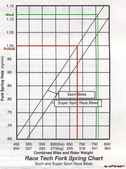
Race Tech Diagram spring rate recommendations
According to that chart I should be using a spring rate of 1.1 kg/mm?? Jebus I already bought the 1.0 and those are stiff enough for me! - But this writeup is about you not me! I think race tech is too stiff for road applications, great for riding at the track but the street its too stiff. Me I would go with 0.9 kg/mm if I had the chance to do it again! Been there done that see here! If I could I would do it again!
How do you do that with stock springs! YOU CUT THEM SHORTER! But not without calculating how much! to get from .72 kg/mm to 0.9 kg/mm the calculation is rather strait forward surprisingly! Just figure out the percentages!
0.9 minus .72 divided that by .72 = 24% holy moly!!!
you need to cut off 24% of the coils to get a 0.9 spring rate? Or you could just settle for 0.8 kg/mm or 10% cut off! Is that even doable what if you cut it off too short? How do you know! Me I read Mark Lawrence's page on doing it and and he shows the calculations, sort of like doing your taxes but its not too difficult!
http://www.calsci.com/motorcycleinfo/Suspe...easeForkSprings
There is also a page for calculating any steel spring rate! besides breaking out the bathroom scale!
I took the measurements 26 coils, diameter .2 in outside diameter 1.2 inches = 52 lb/in divide by 56 = .928 kg/mm WRONG! doesn't account for pitch!
http://faq.f650.com/FAQs/ShocksSpringRateF...te%20Calculator
Calculating how many coils to cut
Back to cutting the springs! Now we need to figure out how many coils we can safely cut using Marks calculations it goes like this!
(a) Spring wire diameter - 5 mm
(b )Number of coils - 26
© Total free length of the spring 375 mm (13 inches)
(d) Spring binding length a * b = 130 mm
(e) Available spring travel c - d = 245 mm
(f) Travel per coil (average) e / b = 9.423 mm
(g) Fork tube travel (manual says) 120 mm
(h) Excess spring travel e-g = 125 mm
(i) Excess spring coils h / f = 13.26
(j) Number of widely spaced coils: count 18 (dual rate spring)
(k) Number of coils to cut j * 24% (from above %) = 4.376
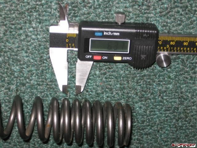
(l) Length of widely spaced coil measured 16.61 mm
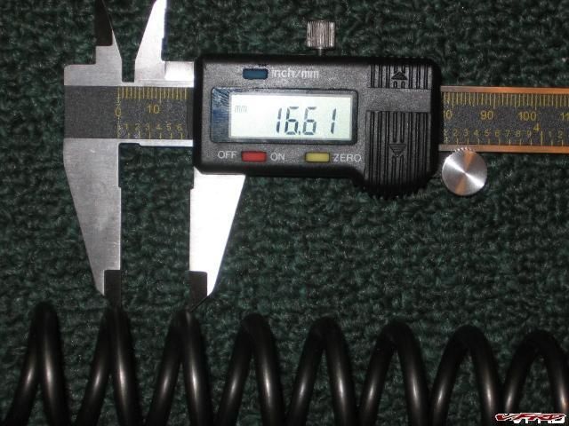
Measuring coil length center to center on long side 16.61 mm or so
(m) Length of stock spacers measured: 50 mm
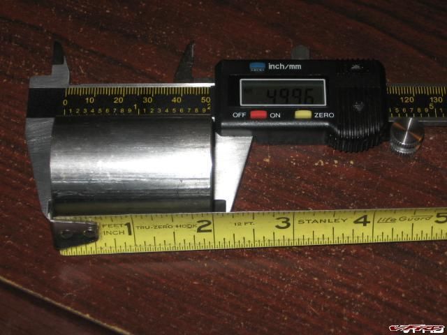
Measuring stock spacer 2 inches
(n) Length of new spacer (k * l) + m + plus a safety margin 10 mm = 138 mm
add 10 mm in case you cut the springs too short and you cant achieve sag, you can always cut the spacer shorter!
(o) Desired Dynamic Sag g / 3.5 = 34 mm
(p) Saftey margin (excess spring - length to cut off) h - (k *l) = 53mm
Now to actually cut off 4.4 coils off! Me I would use my cutoff wheel then grind it off at the end - heating up the coil with my torch to flatten the edge. and your done, some use PVC 1 1/4 inch pipe for spacer material, I use aluminum pipe, or brass pipe even would work.
Attached is a microsoft excell spreadsheet I made with all the calulations above - easy cheesy
-
 1
1
-
-
Riding season is about over and as usual members are logging in more - and as such they are posting more off topic posts than ever.
ON TOPIC = MOTORCYCLING
Let me be clear, vfrd is for motorcycylist, not gaming, current events, cars or any other topic not motorcycling. I really want to make it perfectly clear that off topic spam will be deleted when I see it as I see it. The Other Than VFR forum is not a junk drawer to post jokes, or pictures of cars, cats dogs, or otherwise non motorcycling topics. VFRD has always had a slim mandate, with a very specific purpose and I dont want to see it get off on a tangent - there are a large number of other websites that cater to that so there are always alternatives.
I have heard about members getting bored talking about motorcycles all the time! Yea I hear ya I have heard that for the past four years - you can always log into sport-tourning.net and get that, its a good site with a lot of the same members as here, but with seamingly every subject in the universe no holds barred type of joint. Or Gixxer.com, or Hayabusa.org, COG, whatever, but let it be known VFRD is strictly about motorcycles!
Furthermore the vfrd gallery is specifically for motorcycles only, and motorcyle riding activites. People are uploading pics of dogs, cars, trucks, jokes, whatever. Photos are resource intensive so I must be strict about that as well. All you need to know is this "if its not about motorcycles it doesnt belong here"!
Many of you disagree with this and I know who you are, your still here, I am not trying to be a tyrant, I am just working within the idea, the framework, the objective, the guidlines, the rules, the concept, whatever word you can think of that = Motorcycling! Shoot just read about all the guys switching to different bikes, comparos and such, its all good! Thats motorcycling! (the vfr is still the best bike on the market!!!)
I dont log in much on my work week so these things slip by me, however if I see it I will delete it, if it becomes a problem well............I dont want that to happen - so thats why I felt I needed to say all this.
I am not pointing fingers at anybody here or singling anybody out nor am I upset about this, I am actually coldy unemotional about it. The fact is vfrd is growing by leaps and bounds, and so many are not tuned into the culture yet, the post counts are pretty consistant, we have always stretched the envelope of how much server space I have on hand, how big the mysql database is its not a money thing, its just keeping it lean and managable. So to keep the integrity of the website lets just keep it about motorcycles! I am asking you all PLEASE!
-
2
-
Best Grade Of Stainless Steel Wool For Muffler Repack ?
in Exhaust Systems
Posted
Yea use the cermaic, you will never have to repack it again.