
HispanicSlammer
-
Posts
6,954 -
Joined
-
Last visited
-
Days Won
61
Content Type
Forums
Profiles
Gallery
Blogs
Downloads
Events
Posts posted by HispanicSlammer
-
-
did a merge post
-
I second Sochiro on the Renthals, I used progrips for a long time, they just dont last. My Renthals though are holding up much better.
-
From what I have read and experienced our very own member Radar makes the best sliders on the market. They do require drilling of the plastics but they are postioned in the absolute best place a slider should be placed. He also gives you drilling guides and there are how to's here that make it rather simple and muss free with a long drill bit, long rode and hole saw that makes the drilling accurate and simple. Read KanadianKens how to on radar sliders. The delrin sliders are large and no hole in the middle they can take alot of force and really do work well!
-
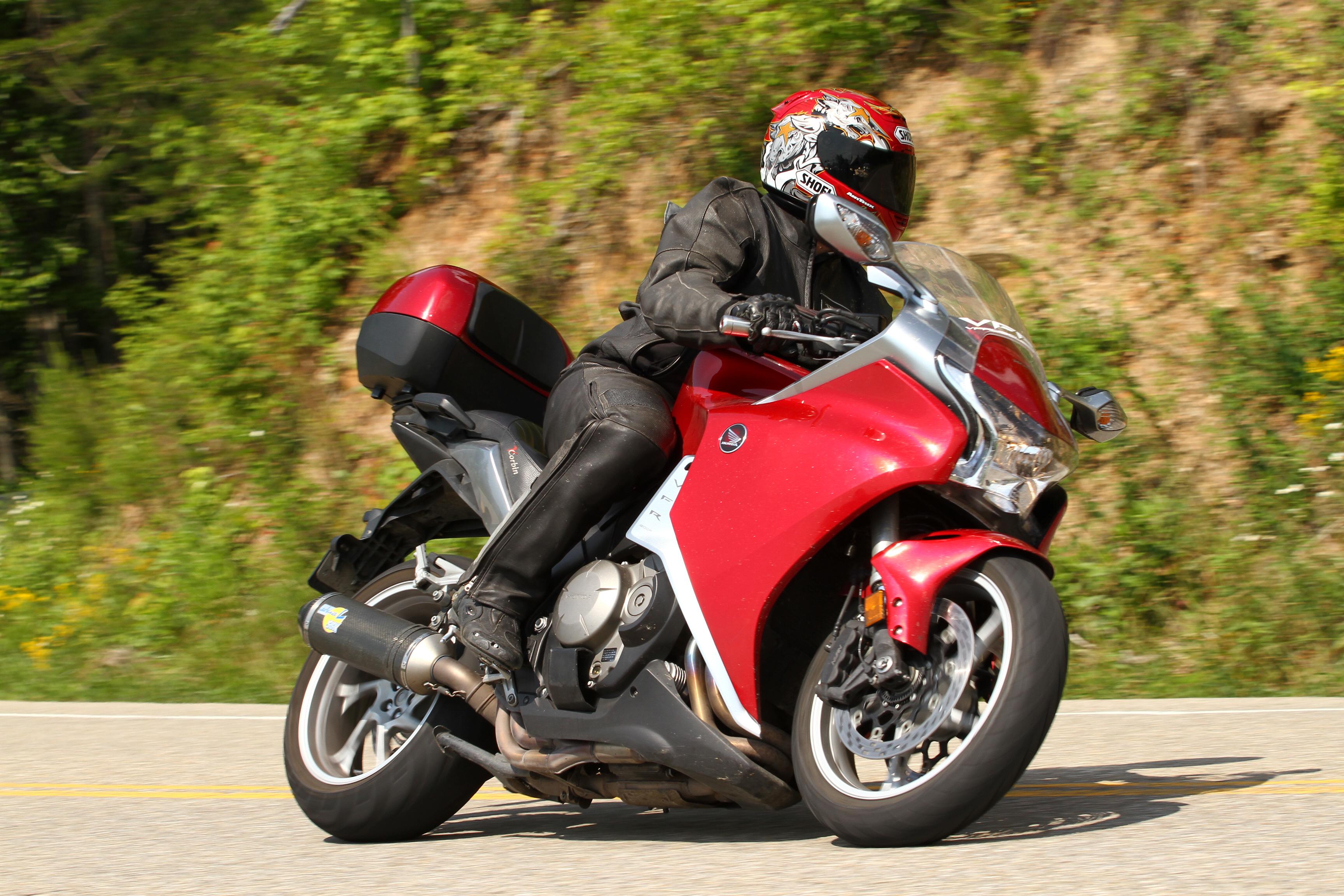
The woods, waterfalls, mist, and motorcycles. Cant ask for a better place to set down!
-
I dont think its worth the trouble honestly, there comes a time when the person behind you is too close having an idiot light might send them into a panic. I actually tend to use the rear brake all the time, just tapping lightly alot with very little pressure. I am also using the front brake - it is just the way I was trained in MSF but it bothers folks behind me to see the brake light comming on so much and they dont really see me slow down. I am - just as much as they, are cause I am not on the gas but I am so lite on the brake that only the light comes on and I slow up very little. - people found it annoying to see my lights come on and then not see me slow down - so I unplugged the rear brake light sensor. I think an engine brake light would just annoy people and it would be comming on and off all the time so much so that when you really do brake hard they are desensitized by it and dont react.
-
Not to mention heavy engine braking really eats up tires fast..
Really? I have never hear of that before? I imagine it works over the rear tire - but does it work over the rear tire than..say if you are just using front and back brakes at the same time? I tend to ride in a style that is suited to the "pace" that is not so much brake and more or less off throttle before the turn, engine braking I suppose then on the gas as soon as I have set my lean angle as soon as possible. I am not a knee dragger either so I am not blazing into turns so fast either.
-
 B
BBrake and clutch bleeding for a Honda VFR vtec
Clutch
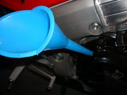
This is cake if you just did your brakes! remove the cap to the clutch fluid, suck it out or use a rag.
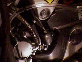
The bleeder bib is on the clutch slave cylinder near the kickstand
 (
( Bleeding a standard VTEC
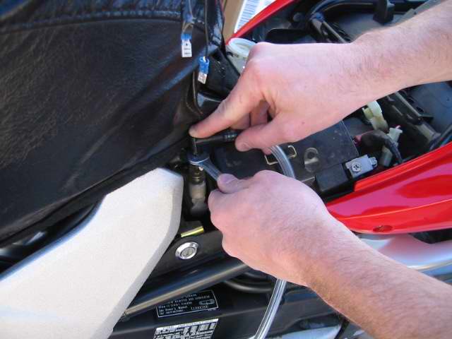
We began by removing the seat and prepping the back area for work. Take off the 2 black Plastic pieces on both sides of the tank. Actually its not necessary to remove the piece on the right side but It could be a bit of a hassle to deal with.
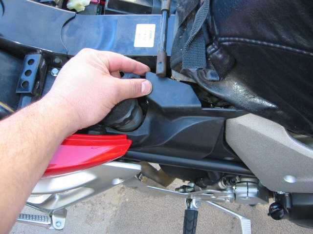
Removeing the Plastic on the right side
With the plastic removed you have more room to work, push in the center of the plastic clips to remove them.
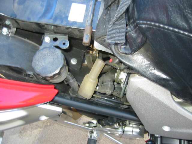
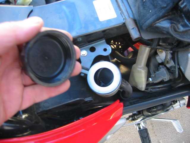
Proportion valve bleeder on the left side
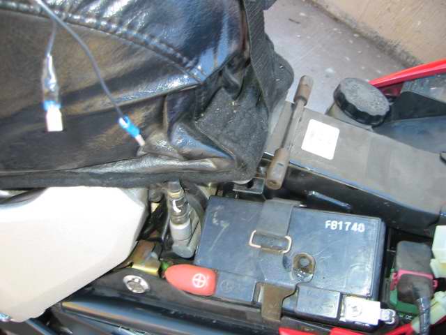
Left side removed covers the proportion valve and battery
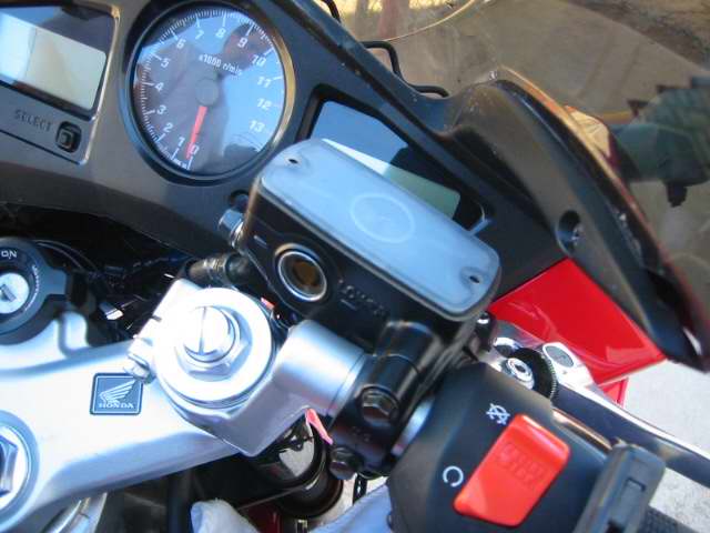
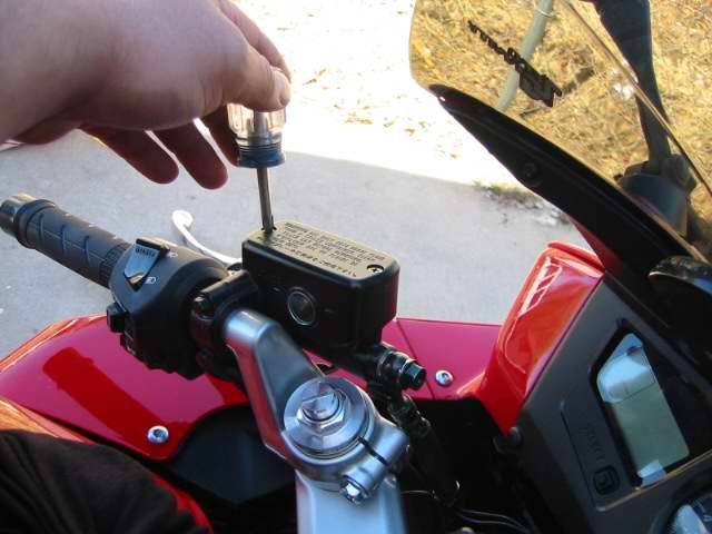
Turn the handlebar to level the master cylinder remove the cap, plate, and diaphram
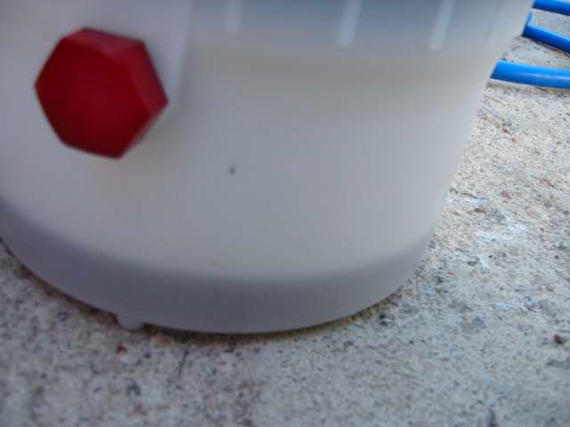
My vacuum bleeder has an auto filler that seals off the master cylinder and siphons in new fluid from a fill bottle.
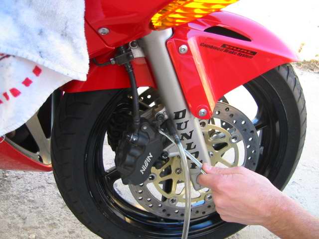
Begin Bleeding The front Brakes
Begin on the right side top bleeder (its the only bleed valve on the right front)
You vacuum until its clean fluid then pump the bar hold it and close the valve. You will get air in the bleeder line its unavoidable, just make sure its clean coming out.
Cruddy fluid still coming out
Now go to the left side and do the top valve.
The bleeders on the calipers are 8mm, after you get clean fluid pump the handle again hold it and close off the bleeder
Top off the master cylinder and your done with the front, put the cap and stuff back on.
Doing the Back Master Cylinder
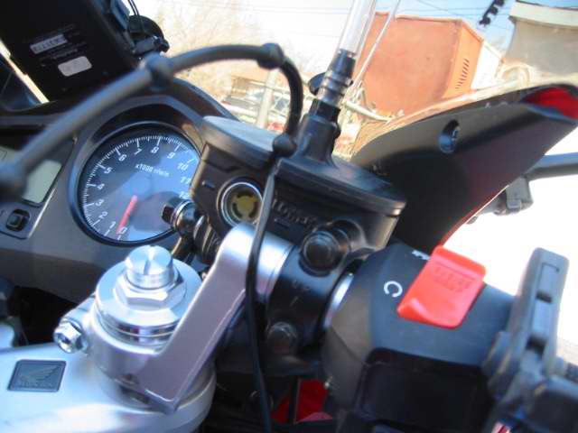
Remove the cap and diaphragm
I suck out the master cylinders first and top off with new fluid before bleeding.
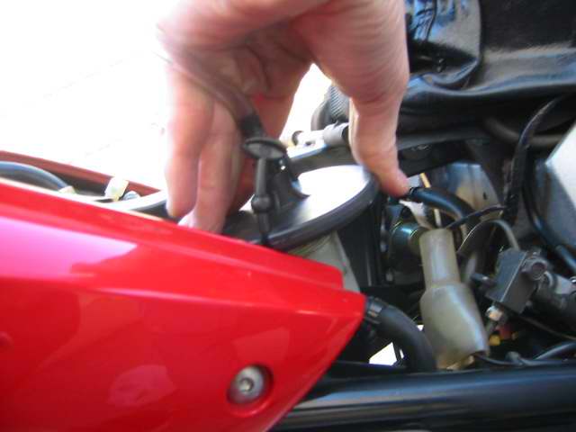
The siphon filler would not seal cause of the ABS plastic was holding it up.
If you spill brake fluid clean it up with soapy water right away or it will eat the paint!
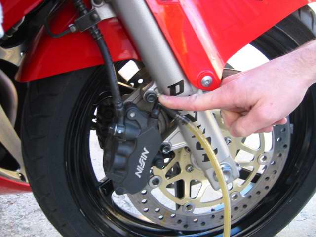
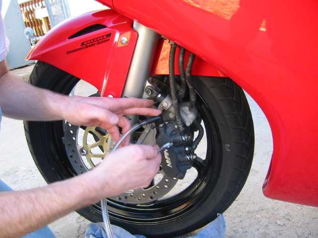
The center valve on the front left caliper is connected to the rear master cylinder start there
They recommend that you remove the caliper and hold it at 45 degrees to help the air bubbles float out, they also say to replace the calipers bolts when you remove them. NAH! Power bleeder!! I just push on the secondary master cylinder above the caliper to pump the air out.
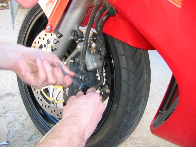
Push on the caliper forward to pump the secondary master cylinder
The Proportion valve wont bleed at all until you pump the petal, its 10mm wrench
Top off the rear reservoir so it doesn't go dry, start with the rear top bleeder
The old fluid is very dark! you will use a lot of fluid to do the VFR! almost a liter, we used synthetic Valvoline brake fluid.
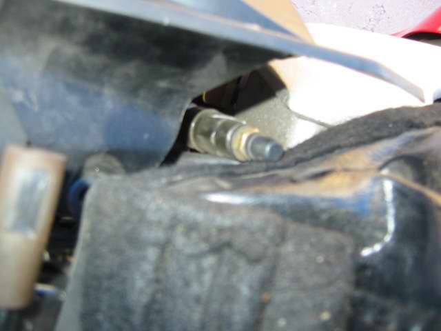
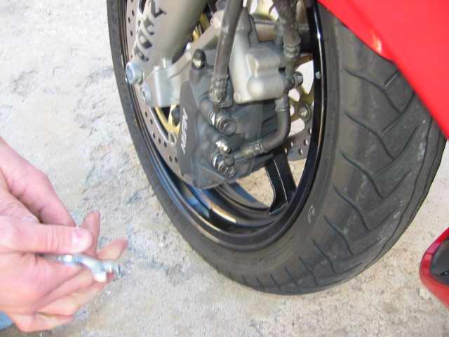
Getting to the valves on the rear caliper is a pain in the butt
you can see a glimpse of the top bleeder in this shot
Again pump the petal hold it and then close the valve, do the front valve after the top valve.
Clutch Line
Remove the cap, suck out the bad fluid, top it off
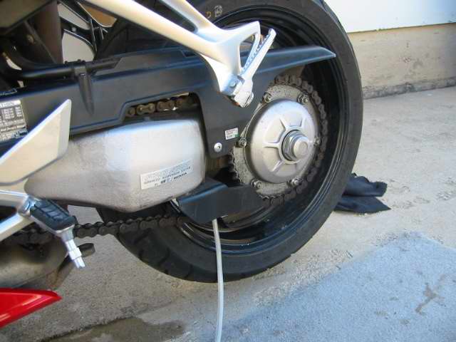
Location of the slave bleeder on the left side of the bike
Check the firmness of the levers and petal and make sure the clutch operates. If you feel spongy then you still have air in the system you will need to re-bleed!
-

This task took a lot longer and it was harder than anticipated.
First time I do it on this bike so I hope this DIY helps others and gives you
a better idea of what you are up against.
1) Remove left side fairing.
I removed the right one first and ended up removing the left.
One allen screw and 5 half turn screws and you can remove the fairing.
2) Use a 17mm socket wrench to open the drain plug. That thing was tight.
Be careful not to drop the bike in the process.
3) Let it bleed.

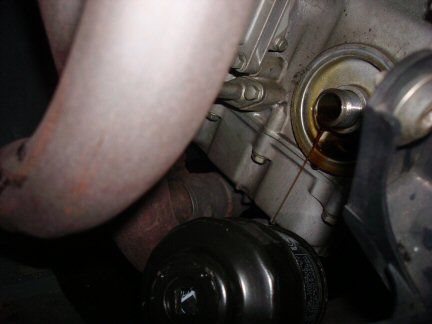
4) So here is the right panel view of the next target in the process.
No way to get to that filter from the right side.
I tried and actually got the socket wrench in there but I had no room to
maneuver and turn the filter. At this point, I'm thinking...
" I should have removed the LEFT panel as indicated in the manual" :pissed:

5) front view so you can see spacing to get to the filter. Not a lot of room.
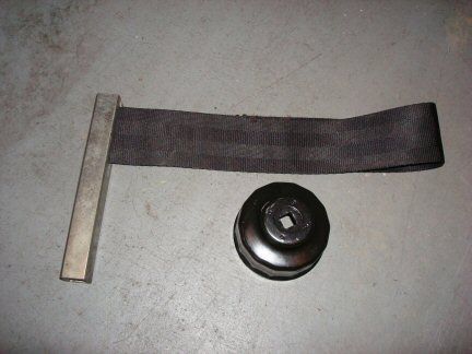
6) Get the right tools for this task. oil filter wrench cap or wrench strap tool.
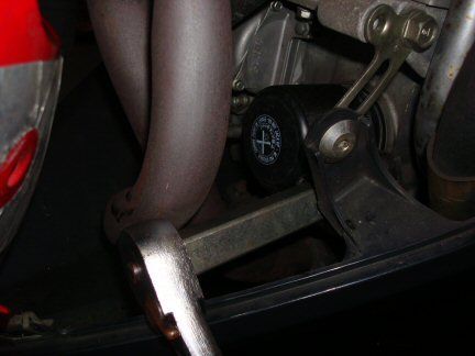
7) Left fairing removed. A little more room to work. I got an oil filter wrench
on the filter but the thing would not turn. I tried and tried and tried.
So, I switched to the wrench strap. That did it.
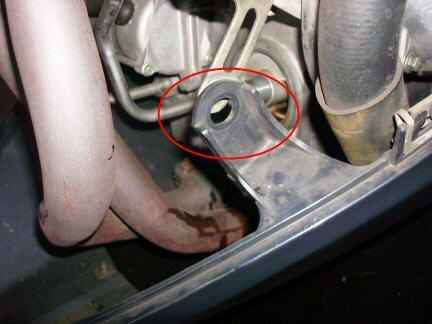
8) Remove the screw that holds the lower black fairing. This will give you
room to easily "pull" the black fairing and have room to remove the oil
filter once you unscrew it.
I learned this the hard way...
I unscrewed the filter and then I realize there is no room to easily
remove the filter from there. Oh well. I just turn in up side down
and let it drain.
9) Clean any spilled oil, attach the new filter, plug the oil drain, give it some oil.
10) I put 3 quarts and then turned on the bike. let it idle for a few minutes
and then checked for leaks at the filter and the drain plug. Add more oil as needed.
11) If all good, put the fairing(s) back on and go get a drink :beer:
12) Now go ride your baby. :wheel:
-
I hope your not going to use vfrd to badmouth another board? Lets just talk about vfrs ok please.
-
 1
1
-
-
I went through all of this when I added stiffer springs, I switched to 5w after installing 1k fork springs myself, it helped with the stiffness of the compression valve, however it gave me a super bouncy rebound. So you have to revalve, less compression and more rebound - stiffer springs need more rebound - changing the shim stacks helps, basically the rebound valve has all the same size shims adding one or two more will help. I cant remember off hand the sizes, but you can remove one from the compression stack and add it to the rebound stack. Or go all out and get it vavled professionally - jamie D had a good offer going for that. I opted for a set of racetech vavles and did it myself. Placed the vavles into an f3 cartridge, and replaced the bushings too, and of course the oil seals.
Changing oil wont help with the basic problem of having not enough rebound compression for the stiffer spring.
-
aw jeez
-

Ok so I got busy the other day and decided to install my ALL Balls Steering Stem Tapper Bearing kit. Ill list some tools I used then a photo essay for you. Plan on about 3 to 4 hours to complete.
Tools/Parts
All Balls Stem Bearing Kit # 22-1020 (good for 5 gen too)
Good grease. waterproof if you like.
Can of brake cleaner
rags
latex gloves
Tools:
Jack
Torque Wrench
Sockets: 30mm, 24mm, 22mm, 12mm, 14mm, 10mm, 8mm
Rachets: 1/2 and 3/8 with small and medium extensions
Wrenches: possible crescent wrench if you dont have the bigger sockets.
Punch/chisel set Long punch needed to pound out old races
Phillips and straight screw drivers
5mm allen socket/driver (cowls and fender )
6mm allen wrench
Bearing Race driver or press is recommended
Hammer
You do not have to take the nose off if you dont want but I dont like fighting to get into places (like the lower bearing race). I decided to take the extra 10 minutes and strip my plastics off. This was a good thing as I also went ahead and did the following and suggest you may plan for this as well but not covered in this post:
* Change fork oil (I found bent tubes on mine and switched out for spare forks, switching my springs and valves and changed the fluid. )
* Change Coolant (removed radiator from bracket and lower hose to access front pugs). Drain at water pump also.
* Change front plugs (every 8k miles). Will do the rear ones and clean oil k/n air filter in a few weeks when I install the 929 rear shock.
Start stripping off the Side plastics and nose and than jack up front end under headers:


Remove front brake calipers, loosen lower axle bolt pinch bolts, remove axle nut, drive axle out of wheel, remove wheel and then fender.


IF you are going to change your fork oil and/or install and new springs/internals do this: BEFORE you loosen the triple clamps loosen the upper fork caps ( just enough to break them loose) this way you dont have to damage the forks in a vise!
Next loosen the top 30mm center triple nut (may have to turn to full lock to loosen). Proceed to loosen handle bar pinch bolts and remove bars to the side. Loosen top triple clamp bolts and then lower triple clamp bolts. Remove zip ties around fork legs. Remove fork legs


Remove horn wires and horn assembly ( I didnt and wished I did). Remove 30mm nut and then pull off upper triple tree. Carefully bend down the 2 tangs that are holding upper nut and remove upper nut. I used a special screwdriver to loosen the lower nut till loose. Undo by hand while holding lower triple tree. Once nut is loose you can remove upper seal and bearing and drop out lower clamp w/stem


After the stem is removed clean up some of the old grease away from the steering head and races. There are cut outs in the head that allow you to drift out the old races. You can see these in the after shots pretty well located at 12 and 6 o'clock. Get your punch and hammer and rotate from side to side walking the old race out.Clean up old grease out of head and prepare for new races.


You now need to remove the bearing off the lower stem. I dont have my vise set up but it would be easier with one. The idea is the same either way. Start by driving a screwdriver or small chisel between the seal and lower triple clamp to wedge bearing off shaft. Careful not to be hammering and hitting the shaft with driver/chisel, you want to be on the side of it. ALSO be sure to protect the threads on the other end, installing the top nut is a good idea. After the bearing is away from the lower clamp you can use a small punch rotating around the bearing to get it up about an inch till it will slide off.

Clean up the shaft and open up your new bearing kit. There is a special press tool from honda and if you have the $$ Id love to have it but I dont have the $$ or the time. I love new tools and bought this Harbor Freight Driver set $29.95. Had a good size for the upper but not really for the lower race but worked ok. I put both races and stem in the freezer while I greased up and cleaned up to help installation. Plus its just plain COOL :)


After about 20-30 minutes in the freezer I called it good and took the top race out and installed it :

Then the lower the same way. Dont get to hammer happy and make sure the races are going in evenly. I had to take a punch on the lower one to straighten out itself into its new home but it made it safe

I then greased up the 2 bearings by hand. Please people PACK your bearings and not just smear grease on the outside. If you have a bearing packer and know how to use it then good. If not hand pack them using latex gloves and the palm of your hand. You pack into the larger diameter end forcing grease to come out the other side. ALSO you don NOT want grease on the inside of the bearing that goes on the shaft. You want the bearing to rotate not the inner shaft end, so clean it up!

Install the new large seal washer on the CLEANED shaft and then the new greased large bearing. I used the old bearing raced I punched off as a guide to drift the new bearing on. Other people have used a piece of PVC pipe along with the old bearing race to drive the new bearing on as well. However you do it be sure that you are pressing the bearing on VIA the inner shaft of the bearing and never the outer cage or its toast and your done till you get another bearing.

Now install the lower triple into the head and install upper greased bearing, seal, then lower nut.


To finish I used a screwdriver and hammer to tighten the lower nut pretty tight to set the bearings. I then loosened the nut and tighten down by hand as much as I could making sure there was no play in the shaft/bearings. Install the lock washer next then the top nut. Tighten the top nut down just enough to line up the next spot to fold the lock ring tabs into. Install horn and wires. Install upper triple clamp and nut hand tight only. Reinstall forks (making sure your throttle cables, clutch line and wires are routed correct) to a distance of 39mm (stock) from top of triple to top of fork leg. I did mine at 42mm to top of nut. Tighten down upper fork pinch bolts to hold settings. Install the front axle and I wiggled the upper triple back and forth, while holding lower legs between my legs, to help center/align the upper and lower triple trees. Torque upper and lower pinch bolts, Center upper nut. Install handle bars and check for clearance of fuel tank before tightening. Now test to make sure the steering is moving freely and easy.
Make sure you torque all the bolts you removed and put your front tire on the right direction. Reinstall brake calipers making sure pads are placed properly. This is just a quick guide so if you have questions please ask, I may have left something out as I was doing many jobs at the same time. Thanks Brian.
Torque Specs 94-97 VFR :
Top fork clamp 17 lbf-ft
Lower fork clamp 36 lbf-ft
Stem Nut 76 lbf-ft
Caliper mounts 20 lbf-ft
Front Axle nut 43 lbf-ft
Axle pinch bolts 16 lbf-ft
Handle bar bolts 17 lbf-ft
As always I encourage you to follow the factory shop manual when doing any repairs
-
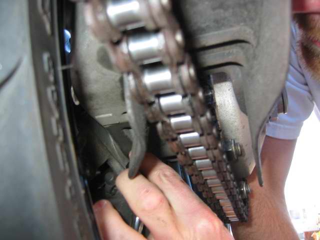
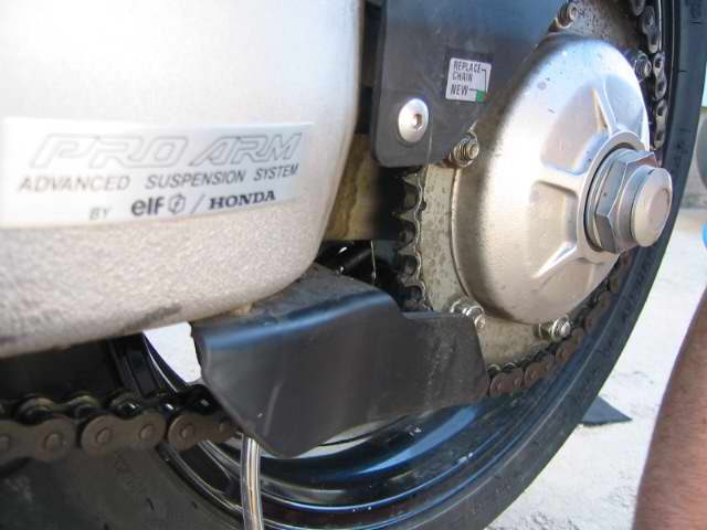
Unless your one of those guys who is looking to make the ultimate lite bike, squeezing out every ounce of wieght you can for some purpose only you can fathom - no its not. If you want your chain and sprockets to last stick with the 530!
-
I pack my tent ultra light ultra small

Black Diamond
Lightsabre Bivy
I bought it not so much for bike camping but for backpacking and just like how simple and small it packs away in my hardbags, my other tent a marmot is much bigger and about 4 times as heavy and large it wont fit in my bags.
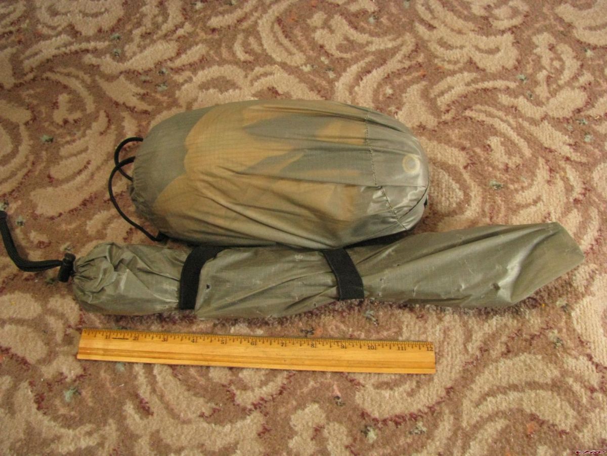
Black Diamond Lightsabre Bivy
-
I spent some of the forum money on an rsvp events system here on vfrd, if you are planning a group ride ask me and I will provide you with a sign up area for members to provide you that important information. I used it recently on the kansas meet and it shows up on the homepage for added visibility for your events. It is customizable and it already has an area for emergency contact info. I still need to tweek it a bit but its a suggestion.
-
Oh also if you have any more videos please upload them to the vfrd server.
http://www.vfrdiscussion.com/forum/index.p...ODE=http_upload
-
Here is an inexpensive speedo, tach, tripmeter. I have one on my XR its completely programmable - if you looking to make it street legal.
-
:wheel:

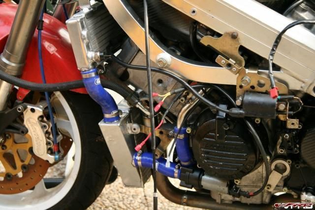
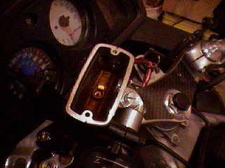
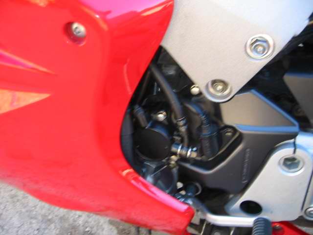
samco.02.JPG
I looked at that picture for 5 minutes before I finnally figured out that the Coil wire was NOT connected to the radiator! For the life of me I just could not figure out why in the world would a coil wire would be connected to the fan switch? Look closer my friend its NOT :unsure:
-

ram mounts one on the gas tank and one on the left clipon I used the gas tank clip on for my Walkie talkie since it is easier to operate the zumo when its closer to the left clipon.
This has been my setup for a couple of years now, but I will take a look at reversing the mount on the clip on.
-
I have always wondered if those wave designs act like a cheese grater on the pads? From what I have read it was a cnc computer mistake that started the whole thing in the first place? I would have a look at your rear brake and make sure the slider pins havent stuck, remove them and put some high temperature grease on the pins. Might as well remove the pistons too and clean and polish those too.
I tried HH pads on my rear they felt way too grabby and I could not get used to the feel. I went with a less agressive pad my next set - the OEM pads have a set of Asbestos pads or some such material in between the metal pad back and the pistons to keep from transfering heat. This prevents the brake fluid from boiling off - the rear rotor is smaller in diameter than the front so you get much more friction going into the pad, with not much stopping power. Just more heat.
-
Kick stand mount
-
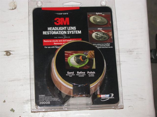
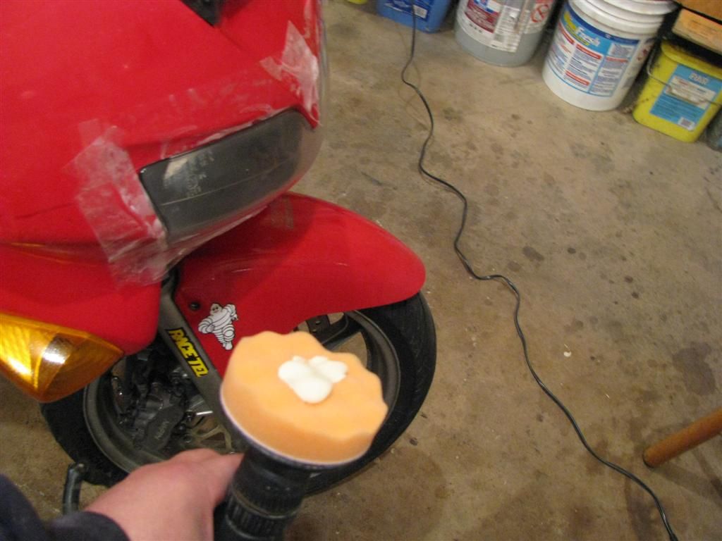
3M Headlight Restoration Kit
My 1998 VFR has its share of dings and defects from riding over 100,000 miles since 2001 when I bought it. It has always had some sort of strange scaling on the headlight like a protective film that was coving it and then half arsed removed. Its been cooked on and it would not come off. Anyway it was getting dingy looking and the light just wasn't penetrating the dark too well anymore so I looked into replacing it (cost prohibitive) then I looked at sanding it off and polishing with the tools I already have and then I decided to do some research and found a restoration kit offered by 3M for around $14-$40 dollars depending on the number of restorations you need to do.
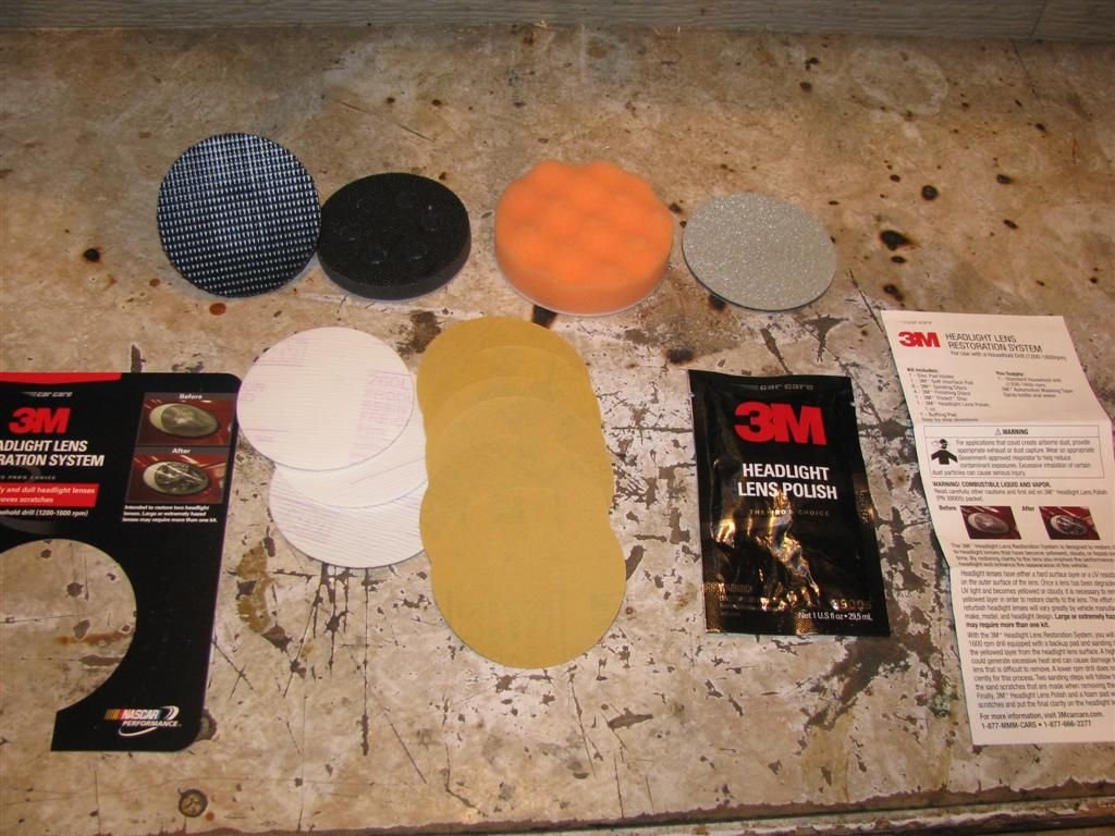
Package includes Sanding disks, foam pad, polish, drill adapter, wet sanding disk and instructions.
http://www.tooloutfitters.net/headlight-le...ion-system.html
You begin the restoration by cleaning off the lamp and then taping off the sections you do not want to get damaged, they suggest using 3M tape of course but I used some packing tape I had lying around since I could not find a roll of masking tape at 3:00 am in the morning - I made due with what I had.

Headlamp before restoration you cant see the reflector, the light is diffused and it blocks the light beam
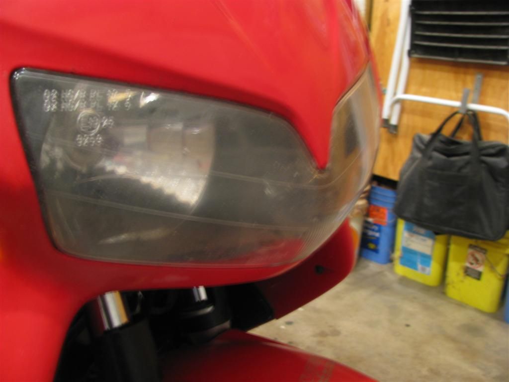
Before restoration you can see the scaling plastic as it has peeled off over the years, the rock chips and the overall dull finish.

3m drill adapter with a 500 grit pad attached
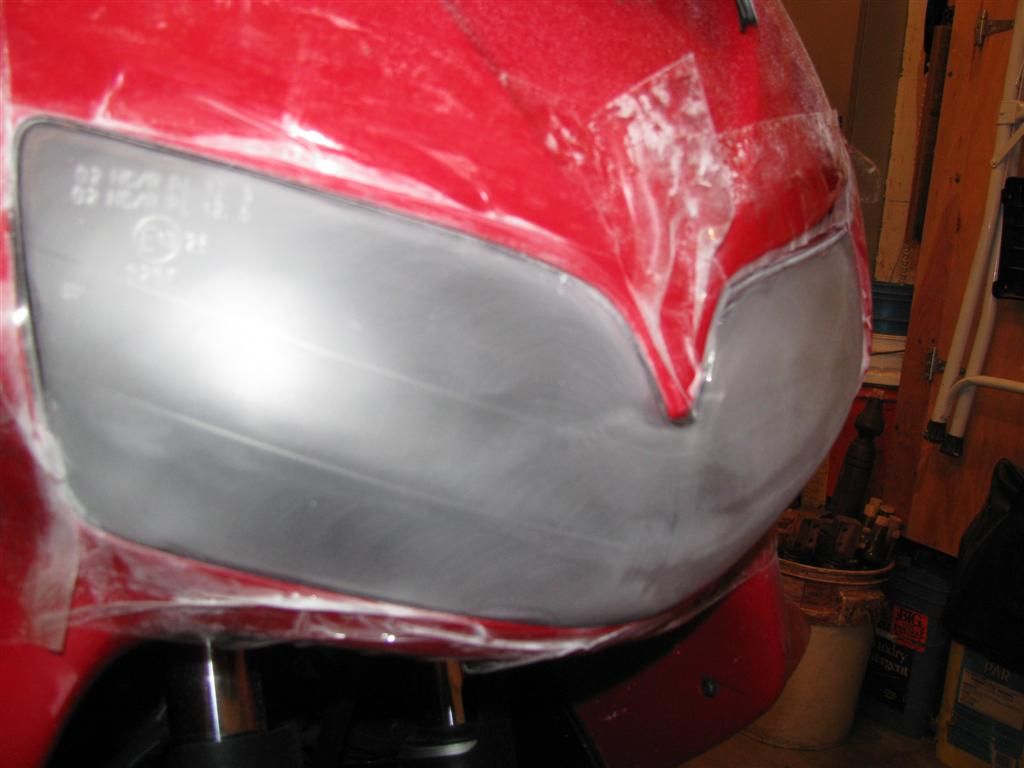
sanding 500 grit completed look for any clear areas, or other defects, use light pressure to sand with the power drill, clean off the powdered plastic and repeat if necessary

wet sanding with the 1300 grit wet disk after removing any defects with the 500 grit, removing sanding swirls with the 800 grit - you clean the lamp and then begin wet sanding
using a dime size dab of polish begin polishing the lamp
turn on the light to view any remaining defects repeat 800 grit sanding if you see swirl marks, wet sand and re-polish if necessary
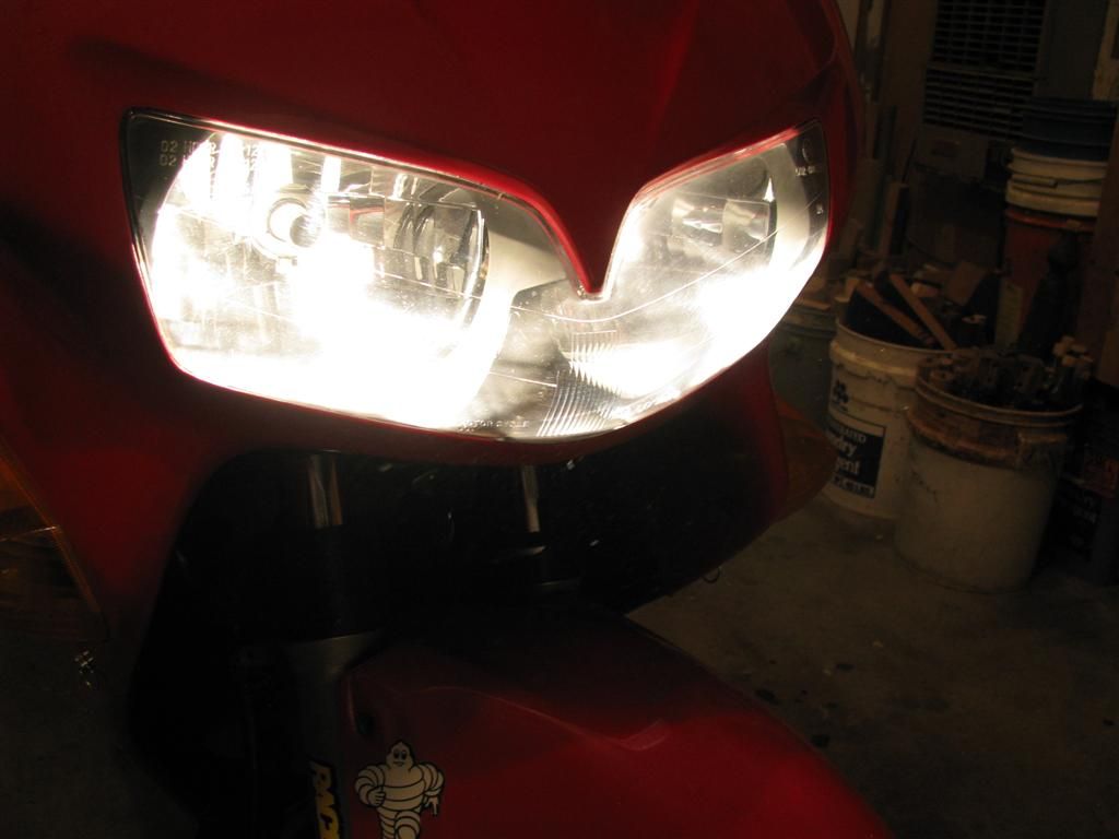
I turned on the light and found some swirl marks so I went back and repeated the process starting at 800 grit and working up to polishing until I was satisfied with the results, then I sprayed on some plexis as well to fill in any remaining swirl marks. The results were dramatic compared to what I was used to it is like brand new condition now - virtually speaking. I am very happy best $30 bucks I have spent on my bikes this year!

Headlamp Restoration Complete
View this video for more details - :media: VIEW VIDEO HERE
-
Unless your Baileyrock in which case you dont have to get on the bike at all!
-
Ok, I am not a writer. I don't have the witty banter abilities of great technical writers who pull you into their project no matter the subject. Instead I am a typical desk jockey who rides VFR and fixes stuff if he can. Before I get into the "easy" way to change the CCT, let me point out that I did not come up with the process on my own. I borrowed bits and pieces from lots of people. The best replacement guide can be found here, CCT change by Rad, where it is done "by the book". In the resulting discussion it was revealed that removing the Throttle Bodies and so forth was a waste of time, as the CCT can be removed without it.
As a second note, I did not change the rear CCT, and I don't imagine I know or could discover any easier way...it seems simple enough already. See the link above to find how to change that CCT if needed.
As a third note (I like notes), I don't believe the CCTs EVER go bad...I think they make noise when the spring loses a bit of tension...more to come on that later (see how I "hook" you...just like the creative writing class said!)
So on to CCT removal and replacement (this order works best I have found)...Anyway, I didn't have music playing, I don't drink beer, and I barely remembered to take pictures....so bear with me. Finding the CCT was the first chore. It is located on the right side, kinda behind and back of the R/R. To find it you need to remove:
Right Fairing
- 8 allen screws
- 1 blind rivet
- Slider (if applicable)
Seat
- Just use the key, and remove
Tank
- two 8mm head bolts, use 1/4" driver
- Restraint Cable
- Two 10mm head bolts at back of tank
Air Box Top
- Hose from top
- screws around perimeter
Air Box Bottom
- Velocity Stacks, Phillips Head Bolts
- Sensor connector on bottom
- Vacuum line going in front of box
- Small connections at the back
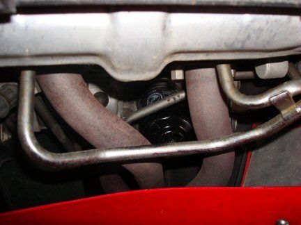
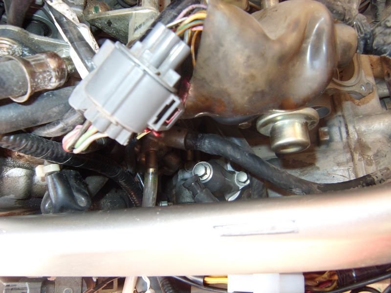
When moved, the airbox looks like this:
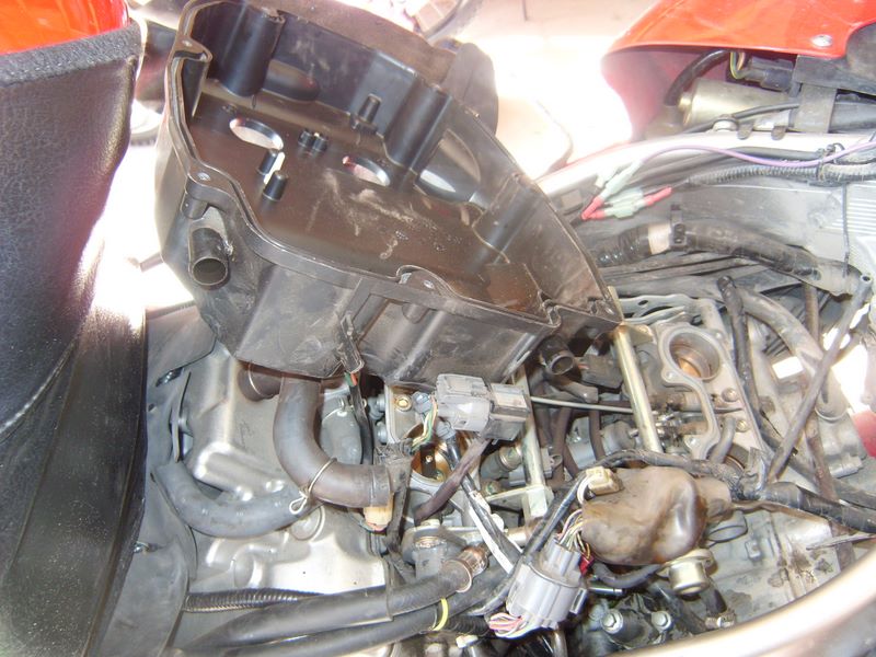
Note the airbox was just rotated away from the CCT. Tank was also rotated the same way and laid across the seat rails. You can see the CCT at the very bottom, just right of center.
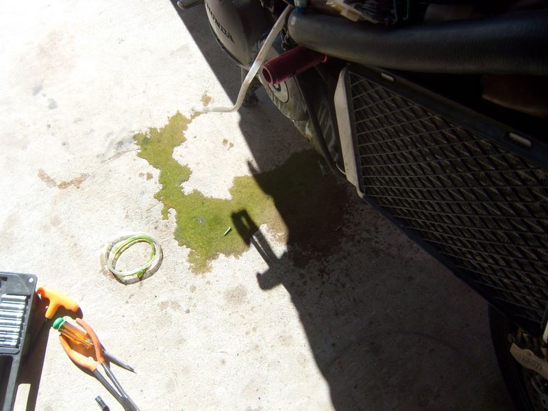
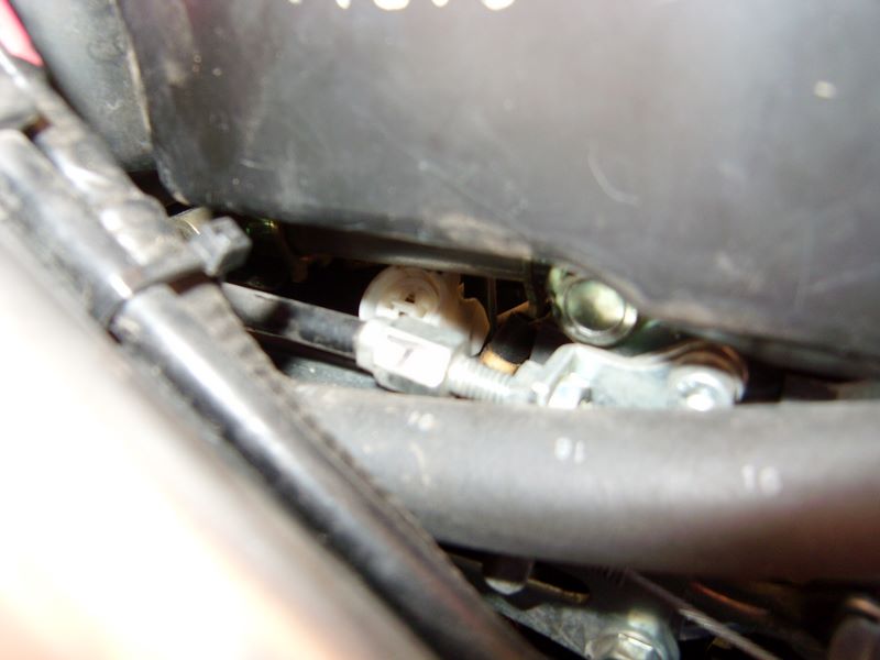
Now you are almost there....just need to remove those cooling hoses to make it stupidly easy to reach the CCT. Remove the one pointing out first, and connect a short section(2-3 feet) of 1/4" or similar hose (I didn't measure it, just some I had around, but 1/4" should be about right).
Route this into a drain pan or later you get this:
next remove the second hose....this is what makes the first connection take a bit of a leak
not much fluid is lost...a bit more than is pictured here:
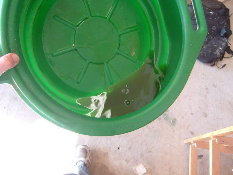
Don't leave this for the dog/cats to drink, unless you don't like them much....
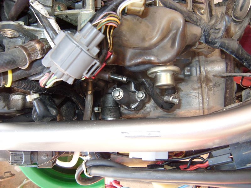
Now it's time to remove that CCT! Simply use your 8mm socket on extension, and take the center bolt out:

This is where the "key" goes in.
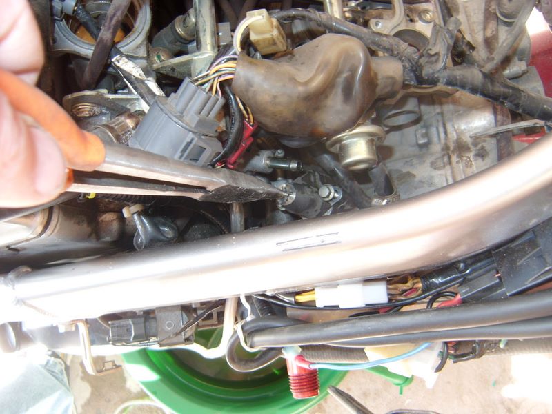
The keys job is to stop the CCT from extending when you remove it from the engine. Keeping it from extending makes it less likely that you knock a bit off into the motor, and also makes it easier for the CCT to clear the various bits above it. If you are really ambitious you could actually rotate the CCT to shorten it and make it even easier...but that would be over kill. After loosing both mounting bolts, and removing them, the CCT just slides right out:
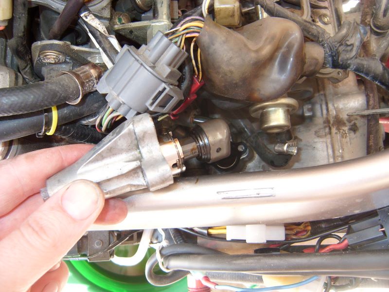
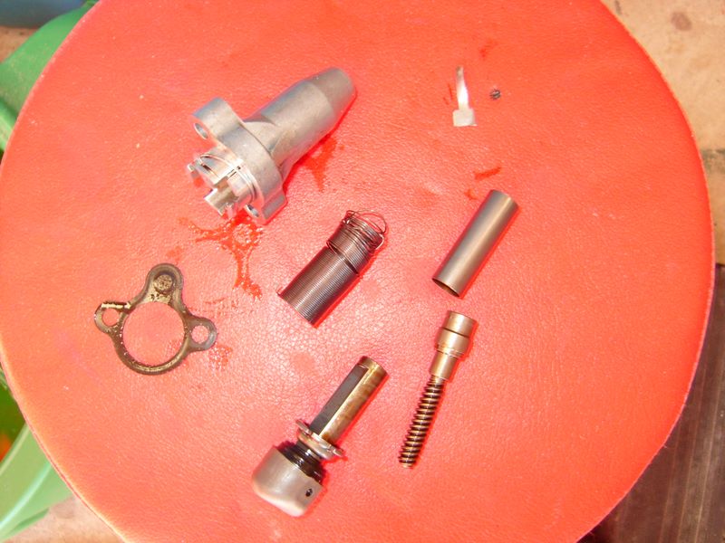
Here is where I have to admit I have a problem. I enjoy seeing how things work. I managed to restrain myself from taking apart my new CCT to see how it works, but the old one was just there....so I had to do it. Initially I planned to try the Reddog idea of tightening the spring....but I screwed up my spring after I removed it, so that was nixxed. Here is a nice picture of my CCT doing it's best Humpty Dumpty impression:
you can see where the spring is messed up....yours won't look like that (don't take it apart to see tho). Let me describe the parts, so hopefully this makes more sense to those who want to know. Those who don't want to know can skip to anther thread or something...
Clockwise starting from the left you have:
- CCT Gasket
- CCT body, with circlip just slid back
- key
- Sping(in the middle)
- bushing/sleeve
- Worm Drive
- Shaft with puck on end
The sleeve/bushing goes around the worm drive, and over the shaft below the locking tab. The locking tab doesn't come off the shaft (without removing far too much).
The way the CCT works is this:
The spring is coiled around the shaft, with one end going into the slot at the bottom of the worm drive, and the other end into a slit at the top of the CCT body. As the worm drive is rotated clockwise, the spring winds up....and if allowed the worm drive will rotate counter clockwise to release tension. The worm drive can only rotate 4 times before the Shaft reaches its stopper. I believe the reason you begin to hear CCT noise is that the spring is able to unwind with a bit of Cam Chain stretch, and thus the spring is not as tight as it was originally. This loosness allows a bit more play that normal, and oscillations begin. Whether different oils help or not I don't even want to discuss.
If you wish to attempt to modify your CCT to save some cash, here is how you do it:
Holding the CCT in such a way that your finger restrains the shaft from advancing, remove the "key". Using a small (probably modified for the purpose) screwdriver, rotate the wormdrive from the access hole clockwise until it stops. Counts the revolutions. It will stop with the shaft all the way compressed. Now reinsert the key, and while still holding the shaft, slide the circlip down so it no longer restrains the locking tab. slide the locking tab carefully up the shaft out of the grooves, noting 2 grooves are wider than the other 2. Then very carefully rotate the shaft counter-clockwise 1-2 times as many revolutions as it took to compress it initially. (this figure is a guess, your results may very, I make no guarantees..written, expressed or otherwise, not available in all locations, subject to rule changes etc). After rotating the shaft counter-clockwise, slide the locking tab back down, and replace the circlip. Re-insert the screwdriver and rotate the gear clockwise to compress the shaft once more. Now you can reinstall the CCT and see if you saved $100.
Reinstalling the CCT is the reverse of removal (I hate it when manuals state that, but it's true. Just check and make sure all connections are replaced or you may not like the results...I didn't.
That is the connector I forgot. The FI light was blinking when I started the bike. I was able to get it back on without removing the air box again using a long thing screwdriver. Speaking of which, here are all the tools I needed to do the job:
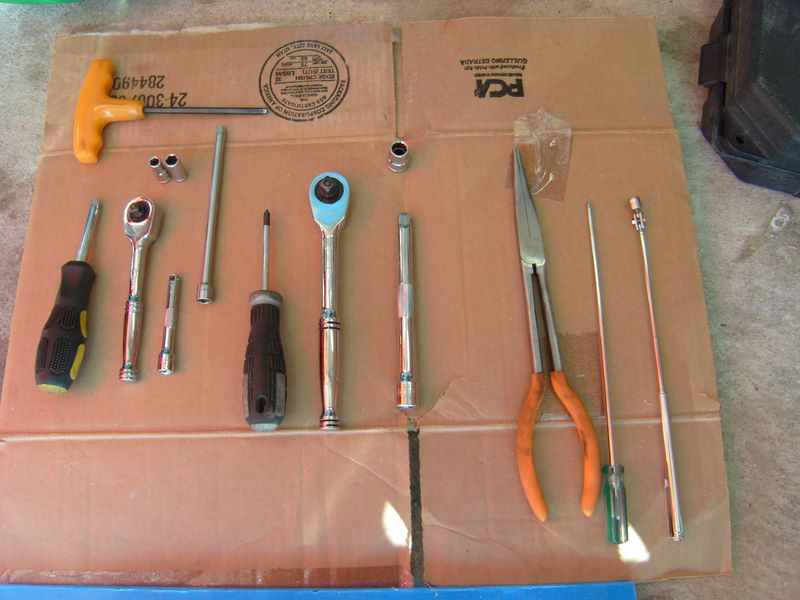
1/4" driver handle
1/4" Rachet
1/4" x3" extension
1/4" x 6" extension
1/4"x1/4" socket for hose clamp
1/4"x8mm socket for CCT bolts and tank bolts
Phillips Screw Driver
3/8" Rachet
3/8"x10mm socket
3/8" x 6" extension
Needed this time, but not always required:
Long Needle Nose pliars
Extra Long thin screwdriver
Telescoping Magnetic pickup tool
Some pictures were not included, you can see them all here:
- 8 allen screws
Repacking an Aftermarket exhaust pipe
in Maintenance Guides
Posted
I did not pack it as tightly as I should have, needed more glass packing. It sounded more throaty, still too loud - it was a D and D afterall. I ended up with a new Staintune the next season. I gave it to one of the wera guys on the forum for track use, it made good power.