

HispanicSlammer
-
Posts
6,954 -
Joined
-
Last visited
-
Days Won
61
Content Type
Forums
Profiles
Gallery
Blogs
Downloads
Events
Posts posted by HispanicSlammer
-
-
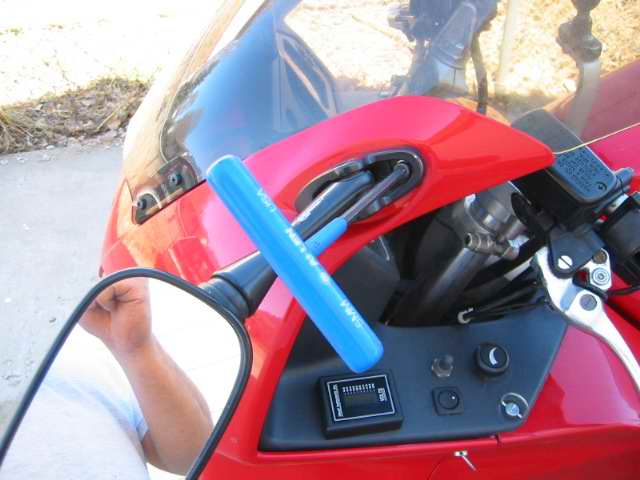
Glad you made it home safe Spinalator it was nice to meet you in person. ?You know I had on the heated vest and the heated grips that trip quite a bit and the meter reveled that I have a bad stator (posted details elsewhere) ?If I did not have the meter, imagine getting stranded in central wyoming with a dead battery and bad stator cause I would have gone on juicing it up with the heaters? ?I did some adjustments and was cautious enough to make it home and test it.
-
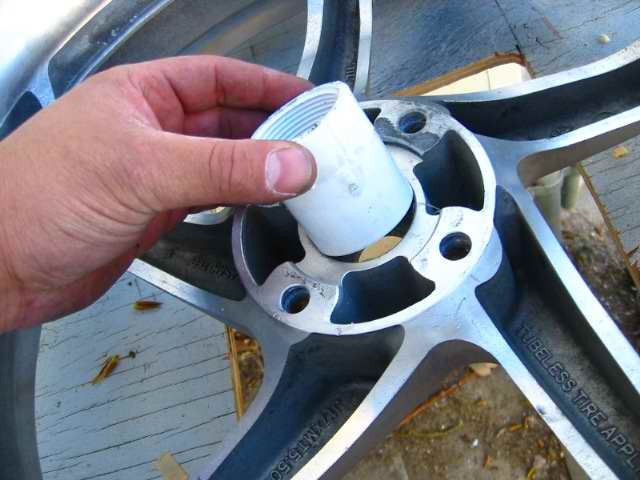
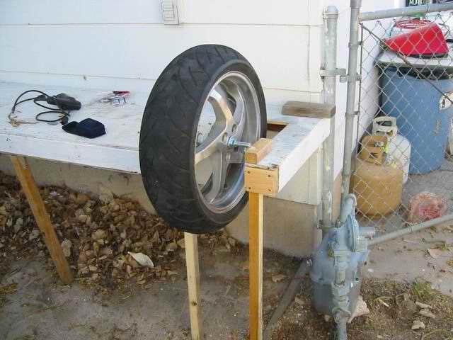
As you May know I change my own tires, up till now I just used a set of jack stands to balance my wheels. But I converted an outside gardening bench into a balancing stand VFR Wheel Adapter
The inside diameter of the hole is about 2" I found a 1 1/2 inch bushing (inside diameter) that fit just perfect, tap it in with a hammer and I am good to go.
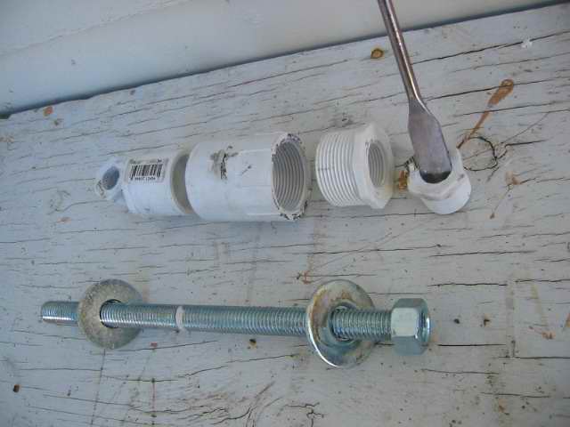
One end of the bushing was smooth the other was threaded so I found some adapters that had 3/4" threads on the inside, and 2 end caps with 3/4" threads on each end, I used a 5/8" bore bit to cut a perfect sized hole for the 5/8" rod washers and bolts. ?I have it set out how it fits together.
The Bench
I cut a U shaped hole in the bench and reinforced it with 2x4s and put legs on the ends, leveled the table and screwed the legs on.
Here are the screen door wheels I used to let the rod turn freely, its just 4 sliding door wheels screwed into a 2 x 2 block of wood on each side.
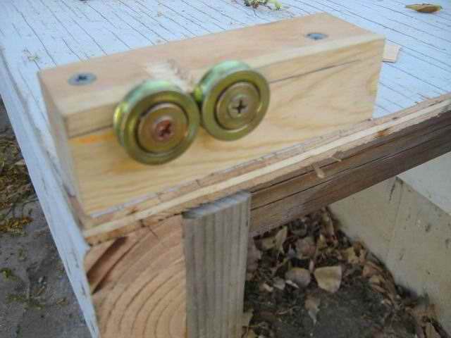
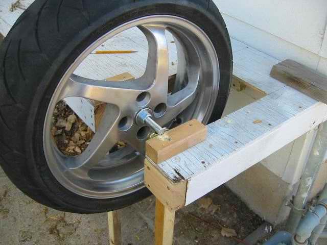
I had to chisel out some wood to keep the rod from rubbing, it sort of screws side to side but not so much I cant get a good balance.
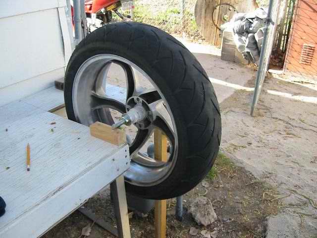
Here you can see how the adapter is used
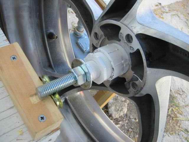
The endcap on the right screw thru the hole in the wheel and it is all tightned down with the bolts on the rod.
Total cost for the hardware $18, bench was already there, the extra lumber was too. Home Depot, Sorry Lewis the post doubled up on me so I erased that one, with the questions you asked, I believe they are all answered now.
I just use the rod to tap out the adaptor when I am done a few gentle taps ?thru the hole and it comes out the other side.
-
Yep that all it is, the OEM switch that turns on the fan grounds the circuit when it gets hot and the fan motor starts, They way I have it wired it will work if the thermo switch gets hot or if I turn it on manually.
So in other words it if the manual switch is off it will still be able to turn on the fan if the thermo switch kicks in.
-
fixed the pictures they were not showing before
-
You can visit the gallery and see how I did mine, there are sections on the spokes that are just cast and not polished, After a year of having them polished there was some sections that had been stained by road salt or acid rain, anyway there were places that had become stained and would not come off without scrubbing hard with steel wool.
On my spokes I put a wire cup on my portable grinder and cleaned them up with a power scrubbing, they look much better now. Some of the brake dust and the paint would not come off in the corners, I used a handheld brass wire brush when I first stripped that off. The brass wire cup attachement to my grinder really make it look shiny on the spokes. I wore a leather apron gloves and safety glasses when I cleaned them up.
-
fixed the pic and the link to the gallery
-
fixed the pictures in the first post
-
I rode up the canyon Saturday the bike does not take as much effort thru the hard turns, not as bumpy as it was going over rough stuff. I also have the Ohlins now so my ride is so smooth now, the only thing is I still have to dial the shock in a bit, its almost right but still playing with it.
I am running about 35mm of sag up front and 30mm in back so it is jacked up higher in the back, a 2mm shim back there too. So the bike steers very quick, sometimes when I downshift I get some rear wheel hop so I think i might need to soften up the rebound compression a little. When I crank on the throttle hard its smooth. The suspension is very tight now, 90 mph feels like 70 used to feel.
So far I have been able to push it fast on some smooth sweepers at about 70-90 mph and it feels very smooth, but have not had some really tight stuff yet so I dont know if Its dialed in all the way yet.
-
Does the switch have a cover on the exposed part? ?If not I you can superglue somthing on there, like I did to Larrys Heat Grips. I cut a rubber section off of a fan switch and glued it to the nut that tightend the switch to the housing.
-
heh you dont want ME drilling a big hole in your plastic! Me and drills are not on friendly terms!
-
From what I read about the moko sliders the overflow tank max coolant line is well below where it is drilled, do they not provide a smaller tank, I thought they did. ?I have seen one that was modified with a piece of PVC tube where the sliders go. That was a good 2" above the max coolant line. It is just an overflow tank anyway, I dont see how they can claim it is the cause of any problem if there is coolant there.
 border='0' alt='user posted image' /> (screen.width/1.75)){this.width = (this.width/1.75)}" onclick="java script:if(this.width > (screen.width/1.75)){this.width = (this.width/1.75)} else {this.width = (this.width*1.75)}" border="0" alt='Posted image: Click to resize'>
 -
Are you kidding, your warranty wont cover you if you install sliders? What about all the stuff I did?
-
Larry did you ever install those sliders?
-
Yea like I said in the first post 35mm.
-
Tankslapper? Perhaps your geometry is too far forward and your getting oversteer, take some preload off the back, get a more neutral feel. 30mm is too high for street riding everything I have read has 32mm as the upper limit for street sag, maybe of you set it to around 35mm you will get a better feel. Just make small adjustments until you get the feel you want.
-
I should point out that 1.0 kg/mm springs are the stiffest spring they sell.
-
Installing Race Tech Springs
I am a rather heavy guy. I come in about 220lbs and dropping :D ! I found that my bike is bouncy - from mostly the front. Last year I changed the fork oil and that seemed to help with the front end diving under braking but the bike is still bouncy. In order for me to get a smooth ride I would have to take off some preload, however in tight twisties it would wallow.The sag was set at 42mm for my trip across country so I could get a smooth ride. I would crank up the preload to a line or 2 showing and get my sag to around 32mm for the tight stuff but then it would get bouncy on the rough roads. So I bought some stiffer springs from race tech to remedy this.
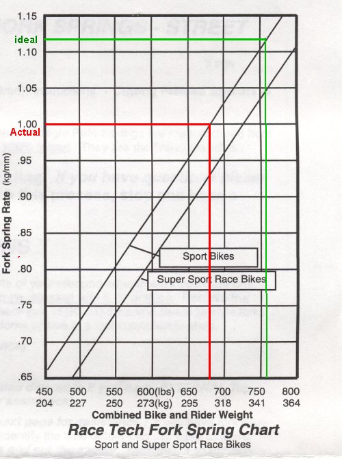
Race tech has an interactive website that will help you determine what kind of suspension pieces you need for your weight and riding style. I used the site to determine the correct spring rate I should use.The Race Tech website Calculated 1.0 kg/mm for me, compare that to the OEM springs which are 0.75 kg/mm. The 98VFR has softer springs than the VTEC.
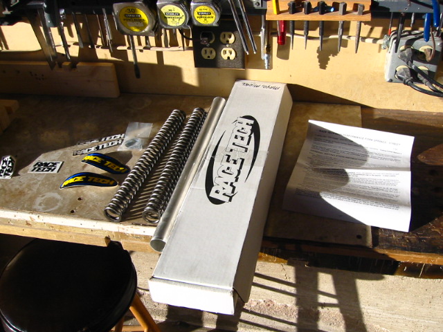
Here is a graph they include in the kit.
The bike has a curb weight of (516lbs) + Rider (220lbs) + Equipment (helm, suit, clothes, tank-bag) (16lbs) = 752lbs
I used a jack to support the bike while I removed the old springs.
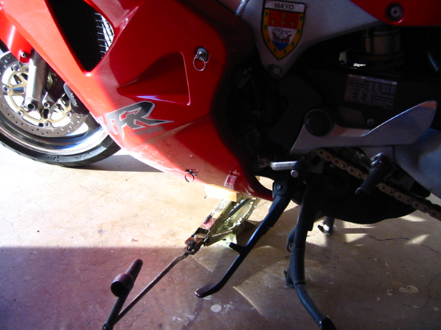
I unscrewed the fork caps with a socket and then lowered the jack slow enough to get at the spacers, cap, washers and springs.
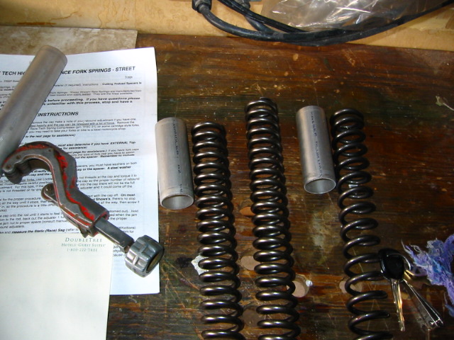
The instructions have some complicated details on how to find the correct spacer size. The Race Tech kit came with an aluminum tube for spacers, washers, 2 springs, instructions, and a bunch of stickers.
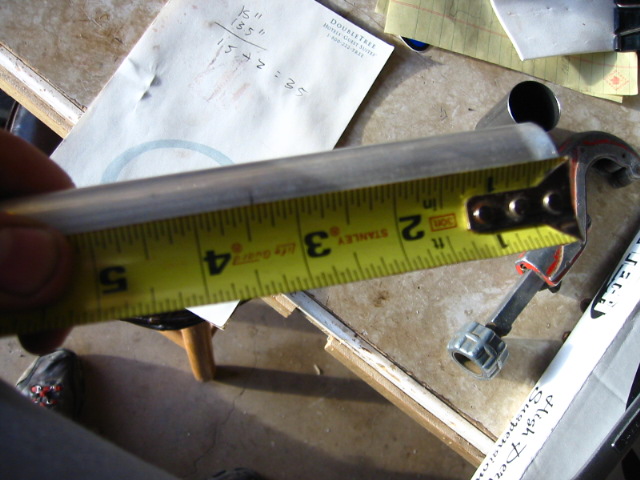
The Race tech springs are 1 1/2" shorter than the OEM springs and they are not progressive wound, (they don't get tighter at the bottom like the OEM) just strait wound.
I just measured the old springs minus the new spring length, then measured the old spacer and added the difference in spring length to that number (see the pad) and cut off new spacers. Everything was actually 1/16" shorter so I just rounded up and then remembered when I made my cut lines.
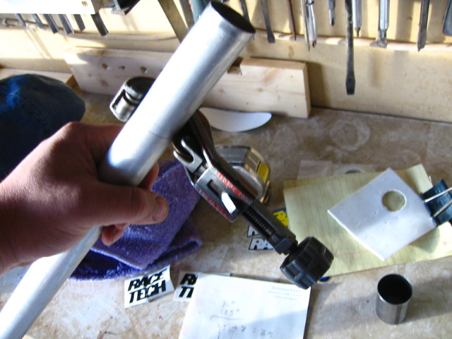
I cut off a small portion on the top because the ends were not square then I cut the pipe to length.
I used the first cut to measure the second spacer
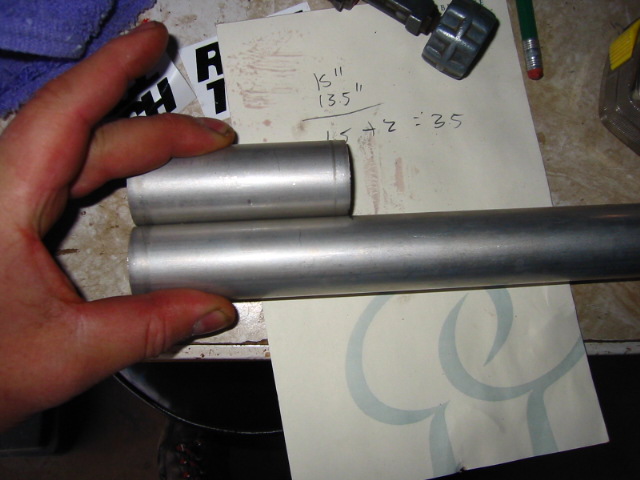
Side by side comparison
You can see the thicker and shorter windings of the Race tech springs compared to the OEM springs.
To finish up I put in the new springs, put the old washers back on, the new spacers, and shims, then I screwed the caps back on. There was some oil loss when I took the old ones out, but very little I let them drip off into the tube when I removed them.
When I put the caps back on I measured the sag at the same settings I had the old springs at. (27mm) is what I came up with. The old one were set at 35mm and I could not get them to sag any less than that. I cranked off 3 lines of preload and the sag came to within 35mm of sag where I like it.
I took the bike out for a short ride and lo and behold its a stiffer ride! :goof: no seriously no more bounciness like before. I still have not ridden on a bumpy road at speed yet but it feels much more stable!
-
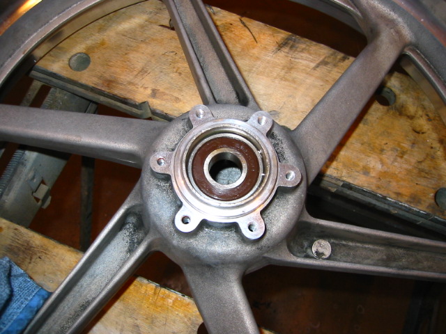
Replace bad wheel bearings I have been getting my bike ready for riding season, I had a warped front brake disk and it tore up one of my wheel bearings from all the rattling when I used the brakes. I don't know if the disk warped first or the other way around. I just had a day of bike maintenance today, new chain, new tires, new bearings, new front disk, new pads.
Here is my new disk, see how poor of shape the oil seal is.

You can tell your bearings are bad if you can move them back and forth or in or out, they should spin but not float around inside there.
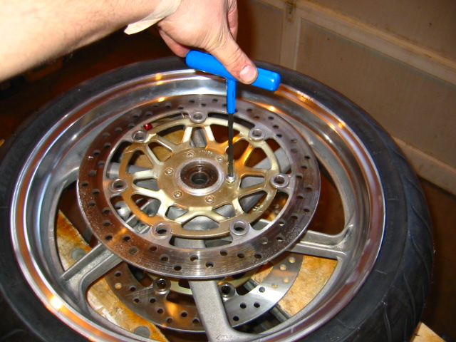
Remove the brake disks 6mm hex 6 bolts.
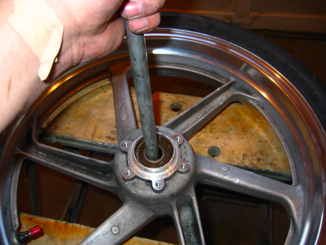
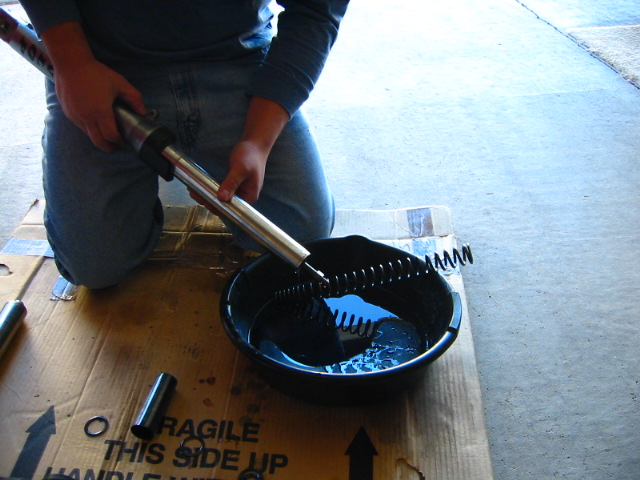
I pried out the oil seals with a large flat screwdriver, then pushed a rod thru the inside and made contact with the outer bearing and hammered it out. You have to move the rod around so you don't get the bearing twisted up.
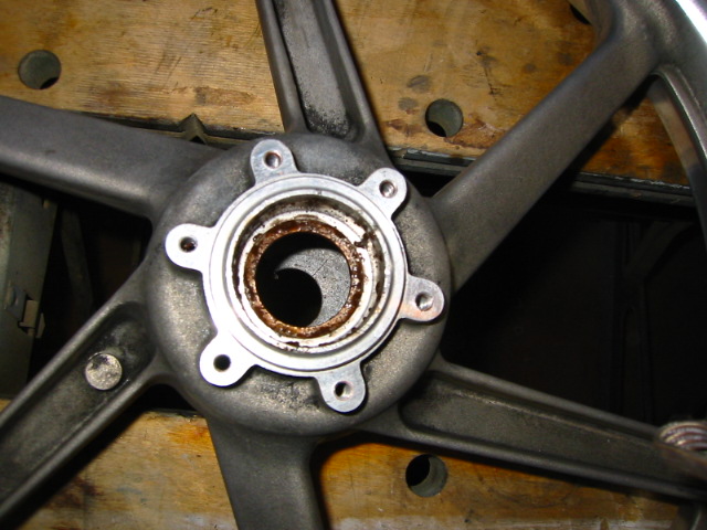
They were in bad shape that spacer needs to go back in, cleaned it up and greased it.
It was rusty in there, I cleaned it up with some steel wool and greased it up.
The new set $46 whew, I gotta find a cheaper source.
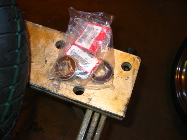
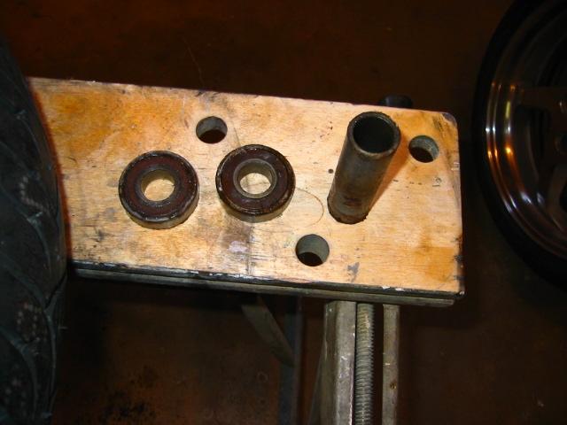
My bearing hammer heads, I use the threaded rod to compress the bearings into the slot first.
Make sure the bearing hammer is big enough to catch the outsides but not too big it wont fit.
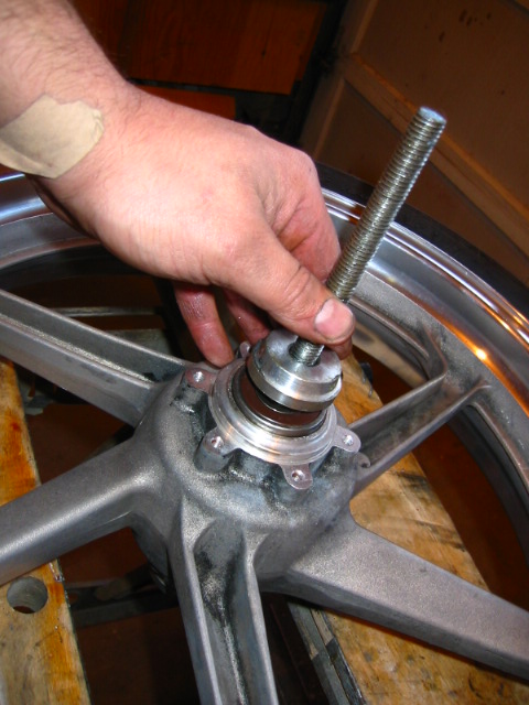
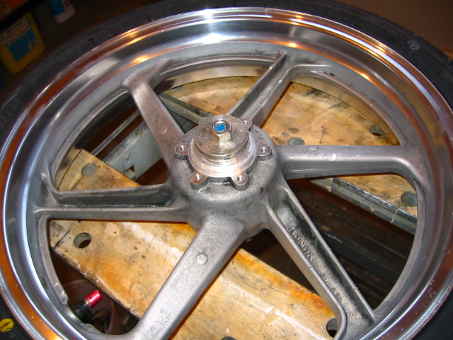
Compress
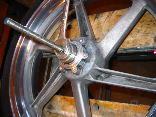
The hammers have a handle on them you can attach and then bang the bearings in the rest of the way. I don't hammer them in right off the bat to keep them in strait and not damage them.
Put in the spacer and do the other side.
-
Replace bad wheel bearings I have been getting my bike ready for riding season, I had a warped front brake disk and it tore up one of my wheel bearings from all the rattling when I used the brakes. I don't know if the disk warped first or the other way around. I just had a day of bike maintenance today, new chain, new tires, new bearings, new front disk, new pads.
Here is my new disk, see how poor of shape the oil seal is.
You can tell your bearings are bad if you can move them back and forth or in or out, they should spin but not float around inside there.
Remove the brake disks 6mm hex 6 bolts.
I pried out the oil seals with a large flat screwdriver, then pushed a rod thru the inside and made contact with the outer bearing and hammered it out. You have to move the rod around so you don't get the bearing twisted up.
They were in bad shape that spacer needs to go back in, cleaned it up and greased it.
It was rusty in there, I cleaned it up with some steel wool and greased it up.
The new set $46 whew, I gotta find a cheaper source.
My bearing hammer heads, I use the threaded rod to compress the bearings into the slot first.
Make sure the bearing hammer is big enough to catch the outsides but not too big it wont fit.
Compress
The hammers have a handle on them you can attach and then bang the bearings in the rest of the way. I don't hammer them in right off the bat to keep them in strait and not damage them.
Put in the spacer and do the other side.
-
Change Your CHAIN and Sprockets
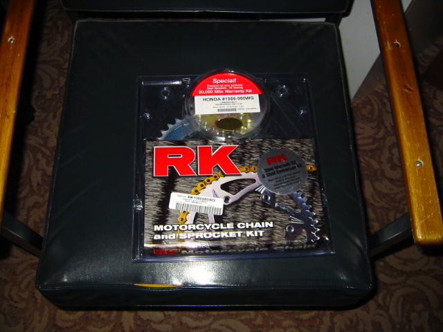
I bought an RK gold x ring CHAIN and sprocket kit from AZ motor-sports for $140, the sprockets are OEM size and steel.
I decided that I was going to clean out all the gunk that has built up for the last 30k miles on my swing arm, CHAIN guides and whatever else needs cleaning.
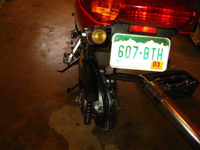
I took off my wheel and moved the exhaust out of the way.
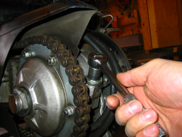
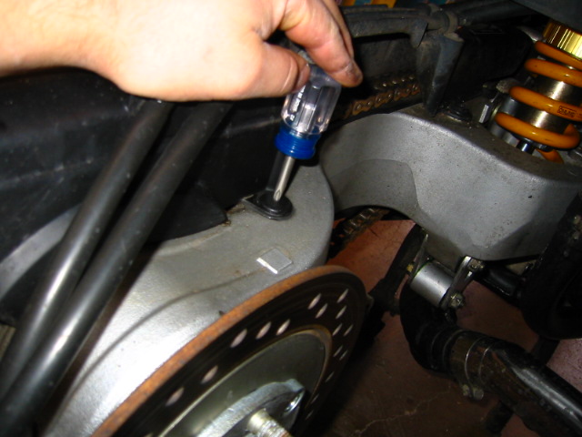
Loosen the 17mm pinch bolt
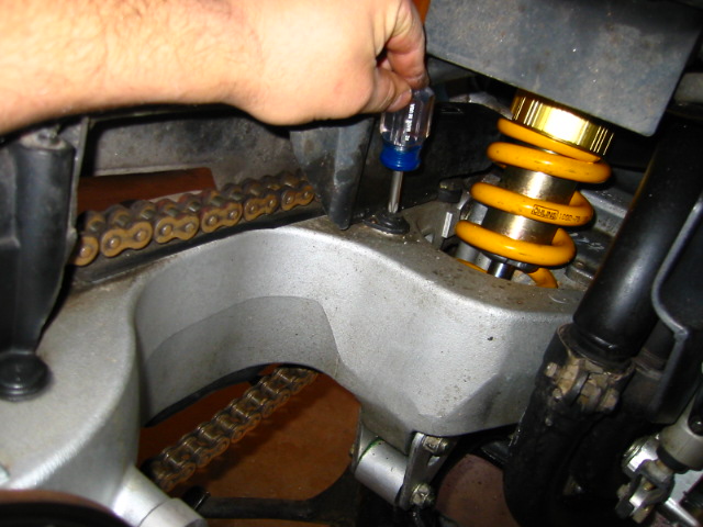
I decided to take off the CHAIN guard so I can clean that too unscrew the 2 plastic fasteners and pull them out.
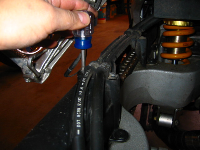
Remove the Hose stays, they bone shaped backers will fall out so be careful not to loose them 4 screws 2 places
Here is a tip - after you clean up your CHAIN guide use some tape to stick the bone shaped backers in place makes reinstalling much easier.
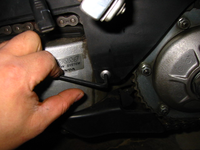
Remove the 2 hex bolts and take off the CHAIN guide.
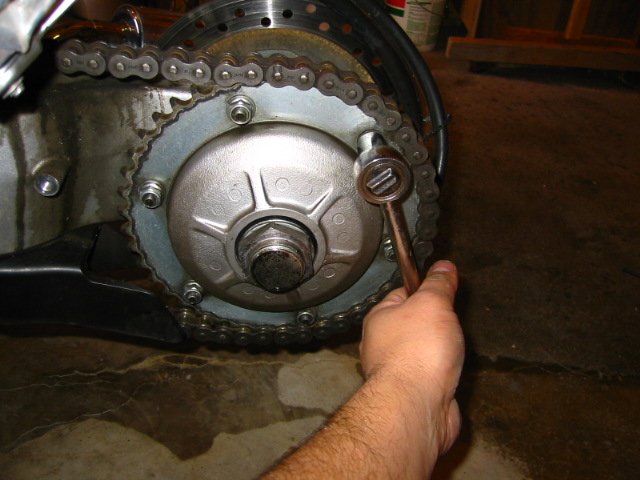
I loosened the rear sprocket nuts
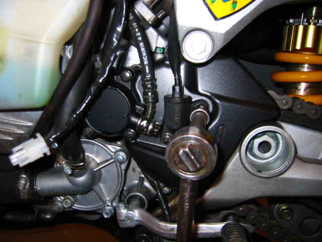
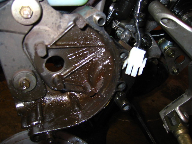
Remove the 6 bolts that hold on the clutch slave and speed sensor to get to the front sprocket, make note of the which bolts go where, they are odd sizes.
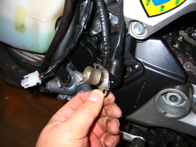
So thats what the speed sensor looks like, it just couples over the bolt on the sprocket.
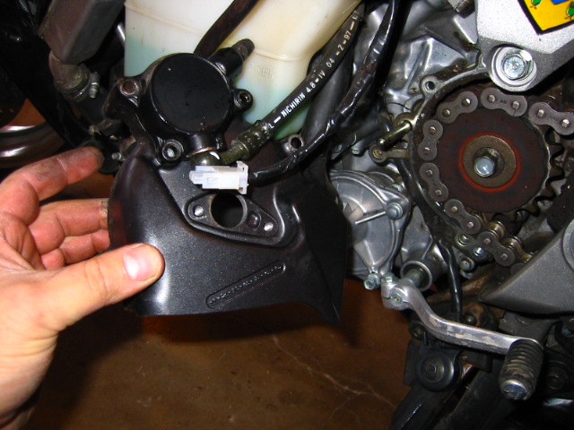
OH my God look at all that gunk! don't loose the dowel pins inside 2 of them.
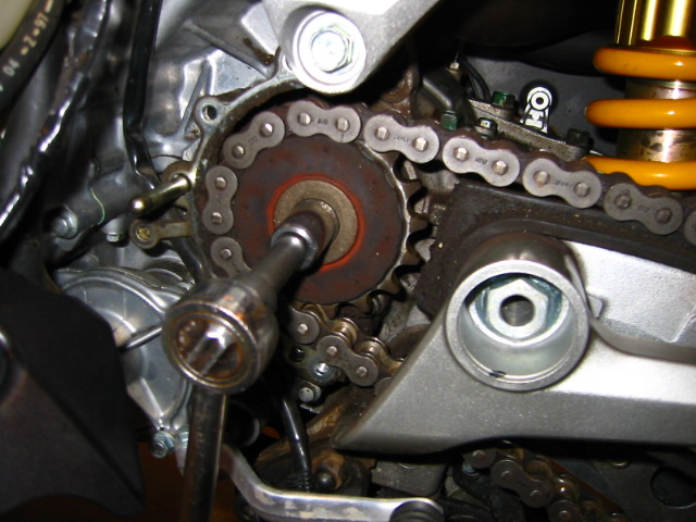
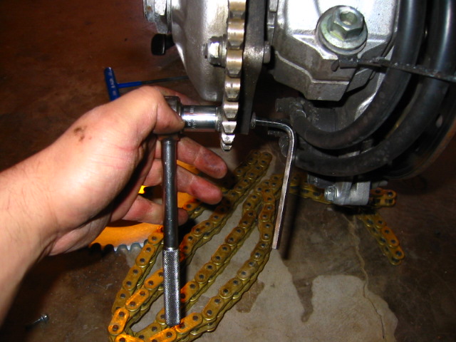
With the bike in 6th loosen the bolt, I forgot the size 14mm it think, its a normal bolt not reverse thread. WAY easier than those stupid Suzuki Hex bolt and nut combos.
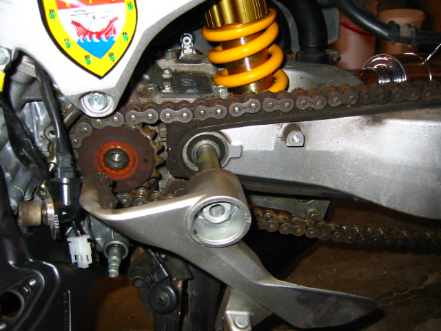
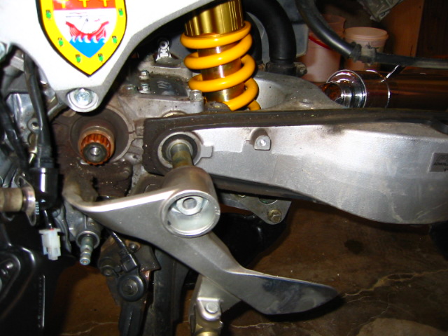
I removed the metal CHAIN guide the crescent shaped plate with the holes in it and cleaned it up, and cleared all that gunk out of there, I just unbolted the swing-arm pivot axle and removed the sprocket and CHAIN intact.
I also have a CHAIN breaker that pushes out the pins but I did not use it since the kit CHAIN is the right length, its a pain to use.
Here is the new stuff
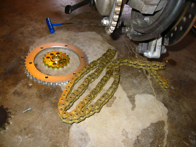
Remove the rear sprocket now
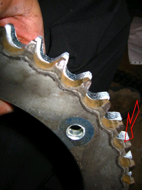
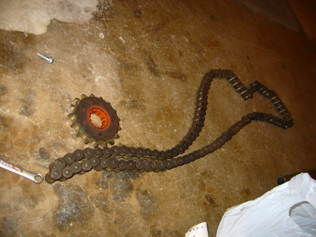
Sprocket comparison, definitely had signs of wear, its hard to spot but these sprockets would have killed my new CHAIN if I had not changed them out too.
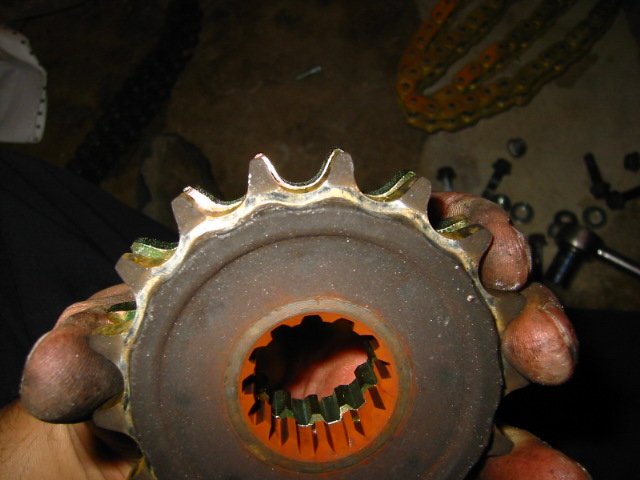
The front does not look worn at first glance
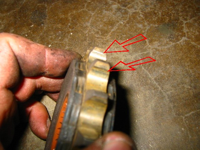
look again
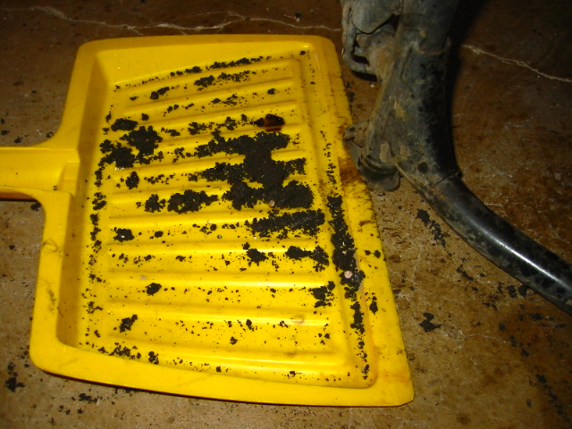
I made a huge mess cleaned up all the gunk inside the sprocket well, the metal CHAIN guide, the CHAIN guard, the rubber CHAIN guide
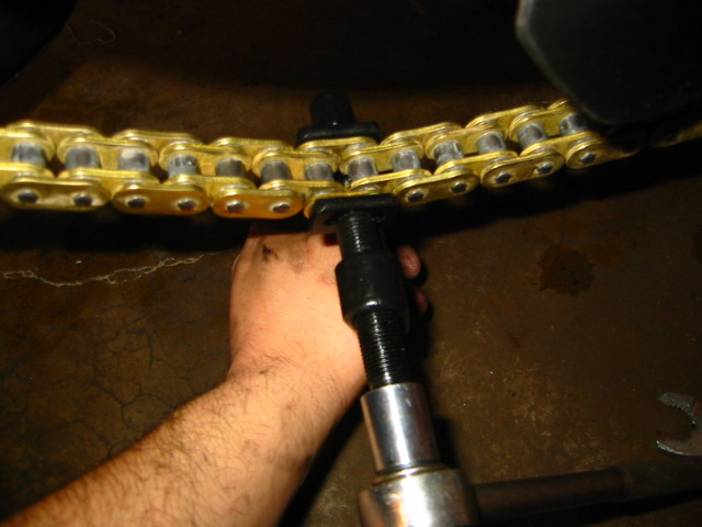
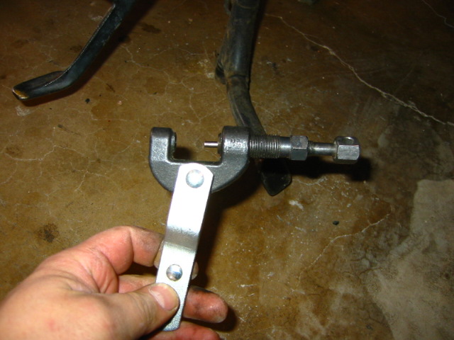
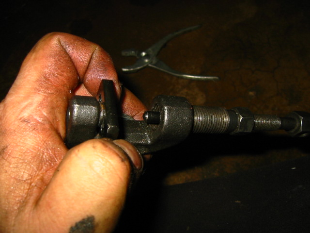
I used my CHAIN press tool to press on the master link.
Pressed on now it need to be peened out. don't forget to put the O-rings on first.
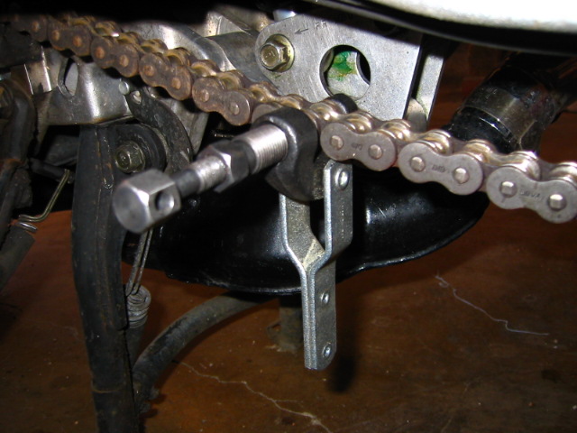
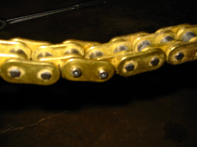
Fit in a rivet peen on the CHAIN too and went at it
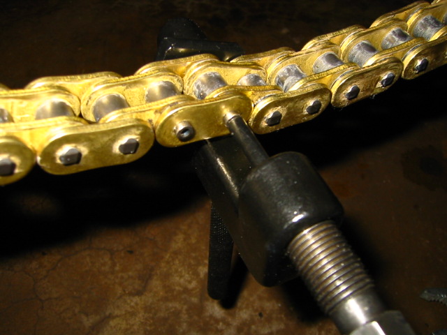
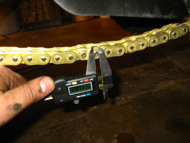
I measured the staked area 5.82mm (5.55-5.85 limit)
Replace everything and your good to go,
the front bolt 38ft/lbs the rear nuts 25ft/lbs
-
 1
1
-
-
Cool you finished up the writeup I will post this in the news section.
-
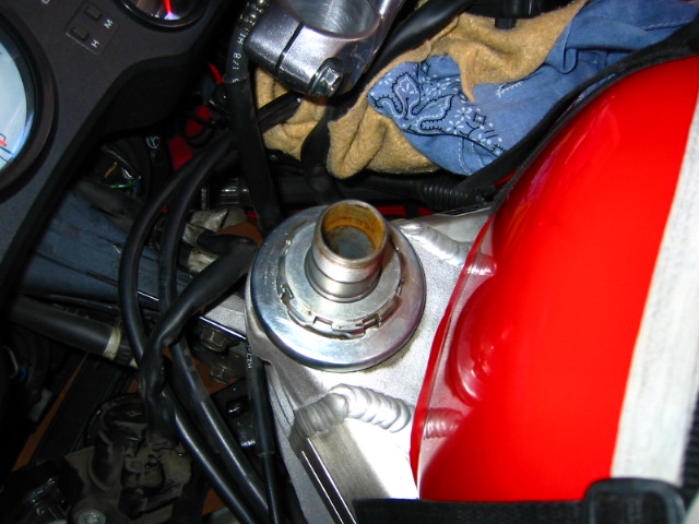
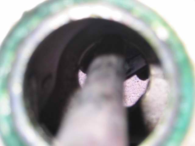
My friend Craig was having some problems with his bike, when he would stop he could hear a clunk when he grabbed brakes. I told him his steering bearings were probably loose.
So he decided to tear the bike down, he removed the steering column and cleaned the races and bearing in some solvent.
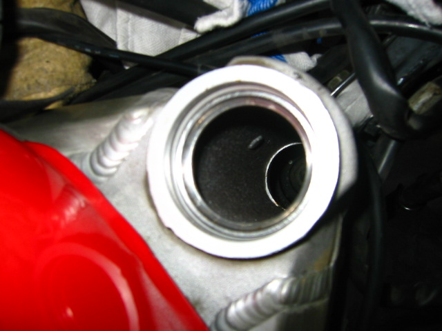
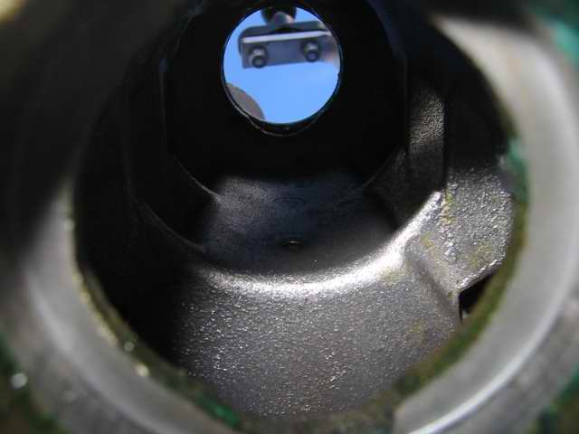
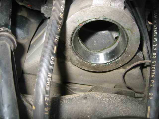
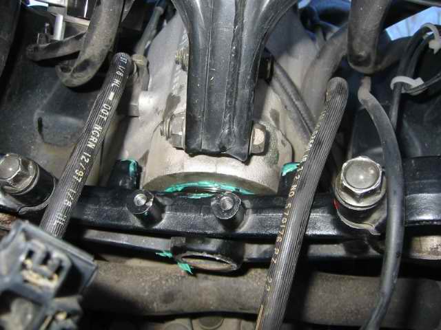
This picture is the steering head, he had already removed all that stuff before I came over.
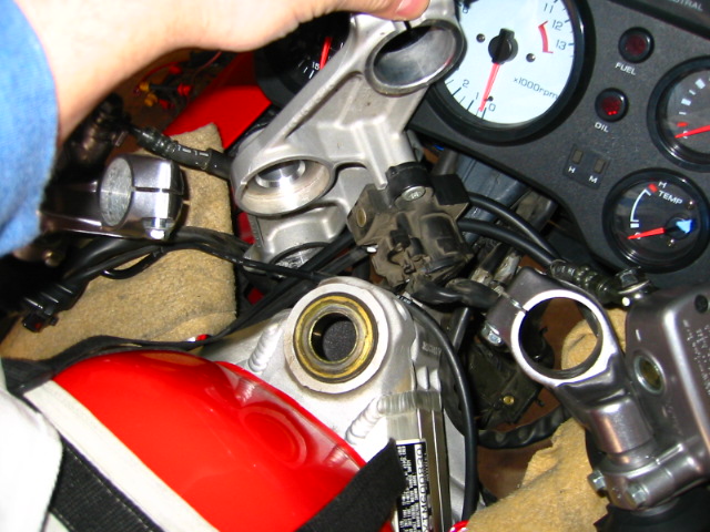
I told him since he had the forks off we should go ahead and change the fork oil since he has 50k miles on them. He said "I am way ahead of you bud" as he pulled out the new fork oil he bought.
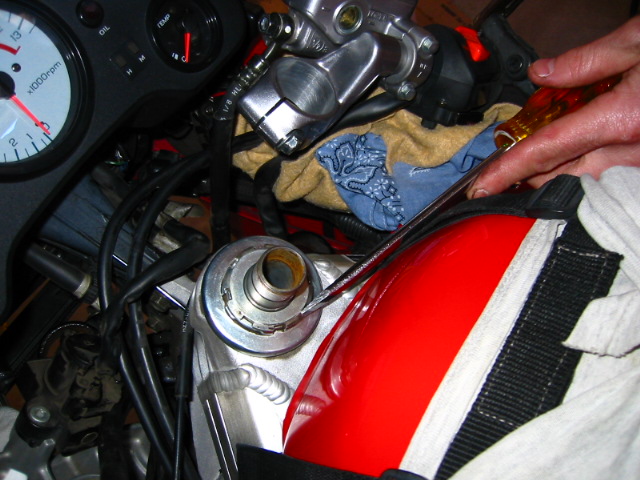
Here I am dumping out the old oil, it was the wrong stuff, it was the 10w honda oil! The 96 VFR calls for 5w clear, this stuff was red like mine which is 10w. Craig said when he took off the forks he noticed that the right fork was sitting 2mm higher than the left one! Whoever serviced the forks last time must have been an idiot!
We could not get the cartridge out since the hex keys he has are the rounded ones and they stripped when we tried to get the bolts out of the bottom.
We just pumped them out as best we could and added the new oil, 14.5oz to a height of 7" to the top of the fork I had to pour some out and add some to get the correct oil height.
We counted the treads to make sure that the cap was screwed in the same spot on the damping rods for both forks, that way the preload would be the same for both forks.
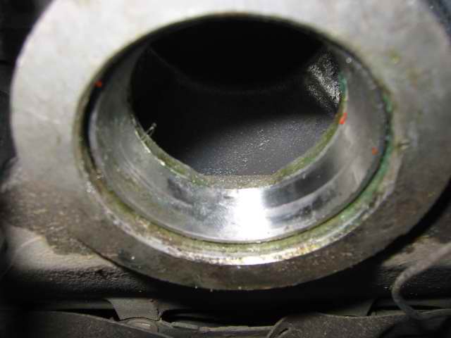
This is the top race, it was slightly pitted but nothing major, I told Craig he should replace them, he agreed but not for the moment.
(The clean bearings before we repacked them with grease.
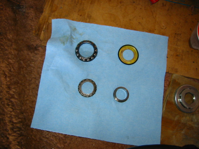
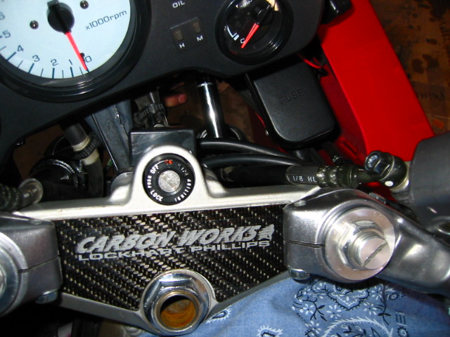
we packed in new grease and slipped the steering column back on fitted on the bolt and hand tightened it made sure it was smooth and not too tight.
Craig tapped on the pinch bolt and tightened it down then bent the clips back in place
Here I am setting the forks to their CORRECT position in the triple tree 39mm to from the triple tree to the top of the fork crown.
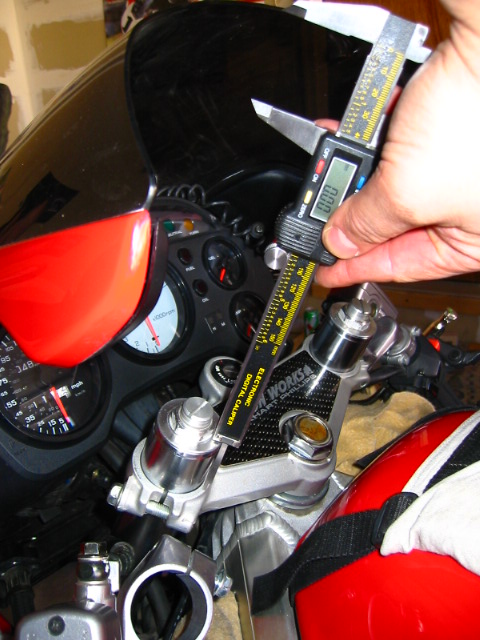
Here is Craig tightening the bottom pinch bolts after I set the forks
We put the axle in to make sure the forks were not twisted in the triple tree made sure it lined up correctly.
We put the wheel on, brakes, and fairings and then we set the sag to 35mm for front and back, he likes a slightly soft ride.
Heh Craig rides really fast and I wonder just how fast he can ride with a bike that is actually set up correctly :goof: it is a wonder how he rode it like that the way he does
-
Well some of you may remember I hit a patch of dirt going thru a corner last summer I almost managed to gain control but before I could stop my foot-peg jammed into the side of the road and I was thrown off the bike.
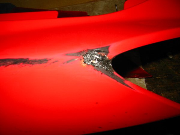
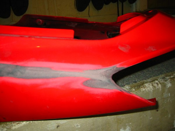
There was some damage to the fairing but the worse part was that the rear fender had torn loose from one of the bolt points, I just shattered a hole where the bolt used to be. My brother in law told me his older brother rides a VFR like mine and he said he had a rear fender that was slightly scratched up but was in better shape than mine, when he came for Thanksgiving he brought it with him and just let me have it for nothing. Thanks Bro!
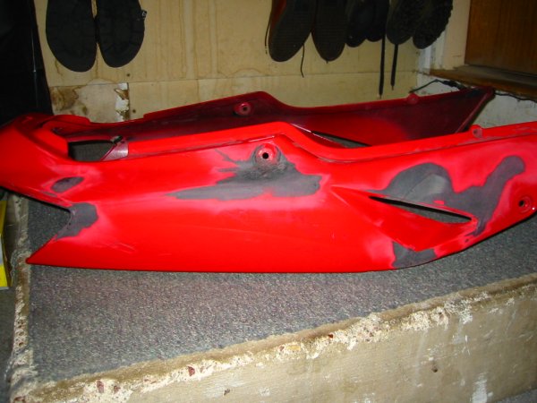
Well it was cracked in several places but it did not have as severe damage as my fender so I decided I would try to repair it. I went to the welding supply shop, they sell a gas plastic welding kit, but I used a hot soldiering iron and some ABS plastic sticks, I just doped in some ABS over the cracks on both sides and smoothed it over as best I could, I had to do this over in a few places cause the extra plastic did not take hold in some cases.
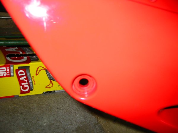
This is a pic of the where I busted a hole in my fender, its about 30 degrees outside so I just took this one inside, this is where it broke.
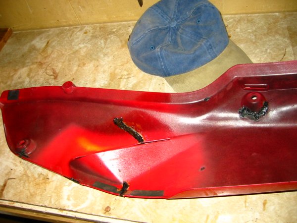
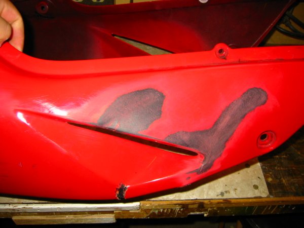
Here is where I welded some of the cracks on the inside
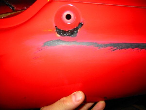
You can see where he scratched it
The point where the rear brake lights was cracked on both sides, I really had to fuse in allot of ABS to fix the cracks
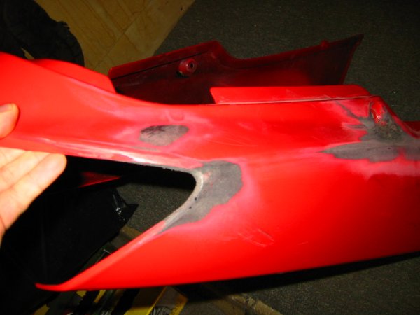
I began to sand out the rough welds here
It is nice having a free fender to experiment on! I don't think I would have attempted to do this on my own fender.
Here I took a round file and shaped the welded part to make it look like it was before I welded it.
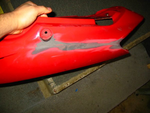
A close up of where I filed it back to shape
I have allot more sanding to do and some spots don't look quite right, the upper holes where the frankenbolts go need allot of work to get them smooth and round. I will post more pics as the work progresses.
-
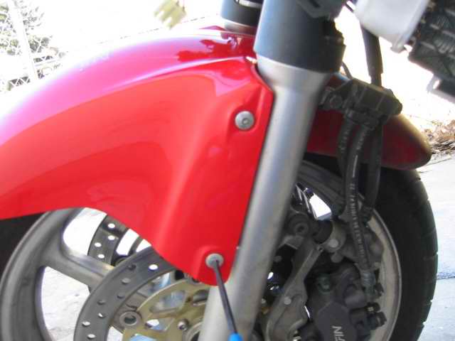
I found that when I brake for a tight turn at slow speed I was getting chatter in the forks, its really unnerving so I decided to tackle the steering head bearings. ?Most of the work involved is taking parts off to get to the bearings.
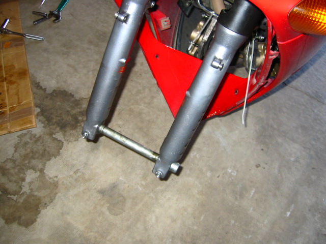
Removing Fairings
The side fairings are rather easy to take off remove all the bolts and just pop it off nice and easy, there are a couple of plastic tabs in the wheel well and 2 more bolts in the scoop, 2 on the very bottom. ?It is the front fairing that can be tricky since there are hidden fasteners under other pieces.
Remove the mirrors - 5mm hex bolts
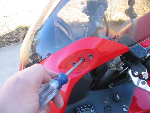
Under the mirror is a screw that must be removed
Remove the screws on the inner moldings
Another hidden screw inside the molding
The front cowl is ready to be pulled loose
Now you can unplug the two lights and turn signals
Remove the fender
Taking off the wheel loosening the axle bolt
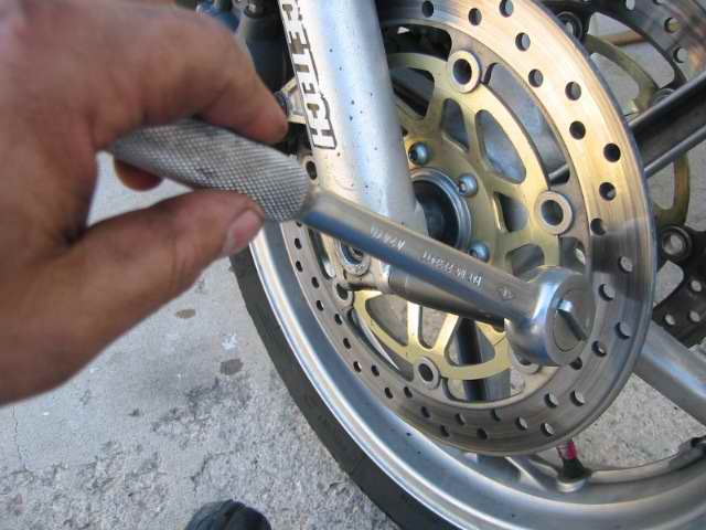
Loosening the axle pinch bolts
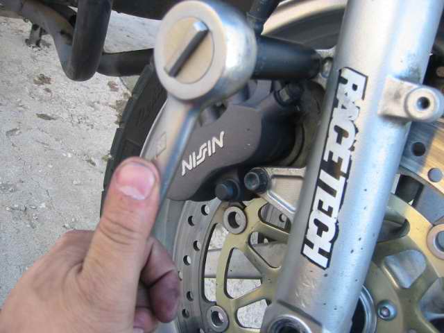
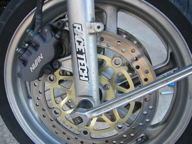
Removing the brake calipers this side is 12mm bolts
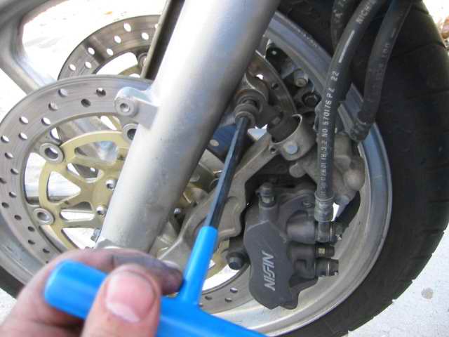
the other is 6mm hex
I lifted the bike with a jack under the pipes and pulled off the wheel, then I started to remove the hose attachments and the horn assembly.
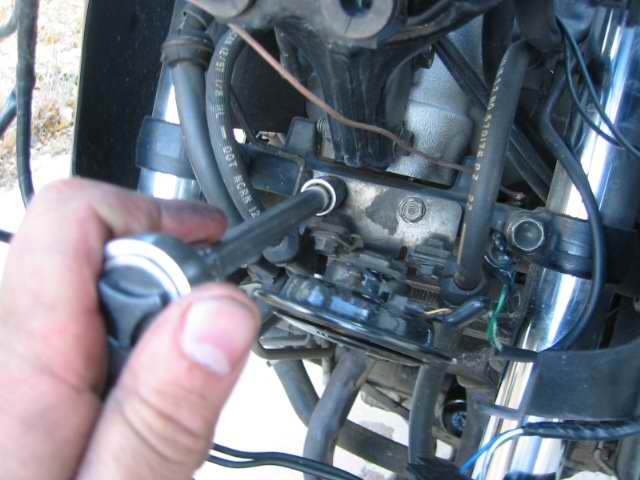
Remove the horn assembly
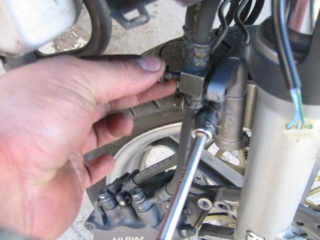
Take off the hose attachments 4 bolts one is behind the hose so its last
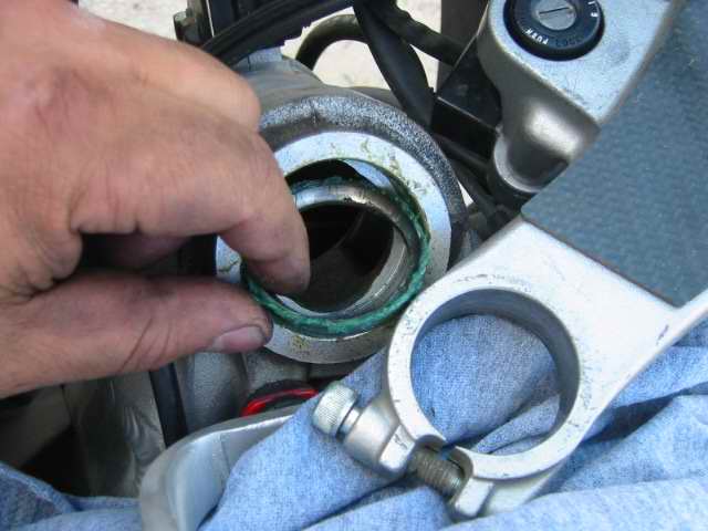
I loosened the four pinch bolts on the triple clamp unbolted the clipons and slid out the forks, I took a card paper and used it to mark the height of the forks in the clamps for easy reference when reassembling. ?I used a large crescent wrench on the top clamp bolt, thats a no brainier it has to come off.
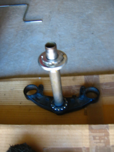
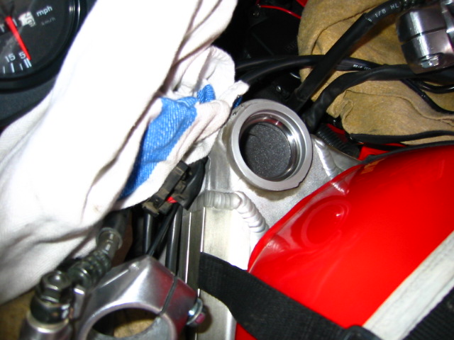
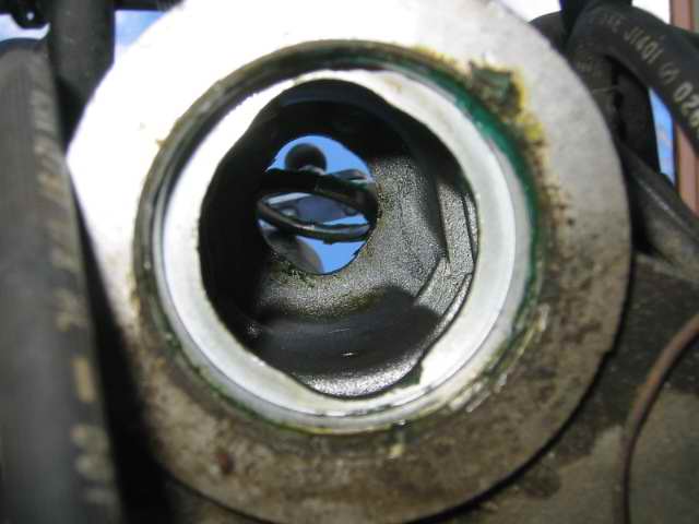
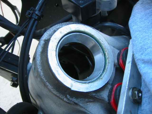
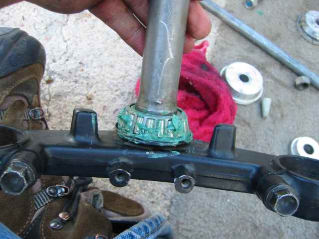
Here is the steering column
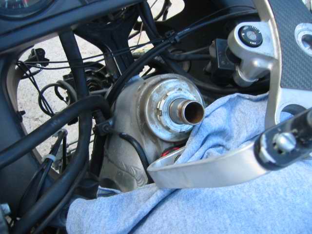
Bend the tabs flat and tap off the top pinch bolt with a hammer and a flat screwdriver.
Honda sells an expensive socket for this but I dint have the time to find it. They are not on too tight Unscrew the bottom bolt and remove the clip, then the column just falls out careful not to let it drop, remove the old bearing sets.
Hammering out the bottom race
The races have to be hammered out, the frame has notches for you to do this, I used a metal rod and hammer and tapped on both sides until they popped out.
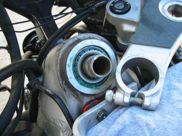
Looking up you can see the notches
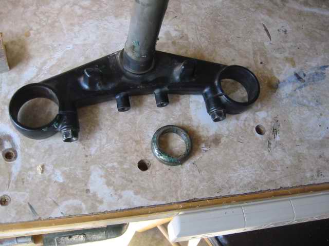
The old races came out easy
The old races where visibly pitted and that was the cause of my chattering forks, too much play in the column does that.
You can see where the ball bearing pitted the race
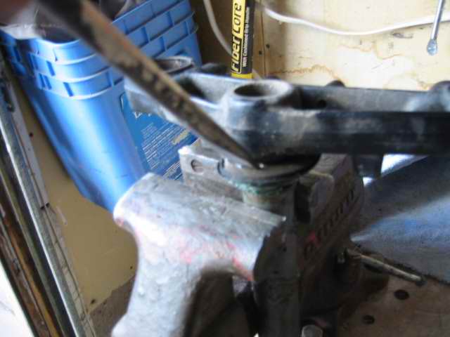
I gently clamped the column and started to hammer the race off
This was a bit awkward, I used a rag in the vice and hammered on each side until the race came off, it took about five minutes. ?I did not use a torch since I tend to burn myself with those. ?It just took patients and evenly hammering it so it would not twist and bind on the column.
Now its off
I saved the old races to use as hammers to make contact with the strong part of the new bearings to keep from damaging the tapered rollers.
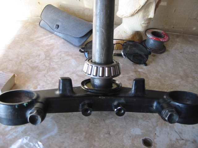
New dust collar and slide on the new bearing
The new bearings are binded with the outer races the old ones were separate pieces. I flipped the old race over and found a pipe that was long and wide enough to make contact and hammered the new bearing in.
Using the old race to hammer in the new one
The inside races are tapered not concave, I have a bearing hammer to use for those. Greased up race first then gently hammered them into place.
Fitted the new race on the bottom
Hammered it in the rest of the way
I have a bearing hammer that has interchangeable heads for different sized bearings, this one fit the top race just right.
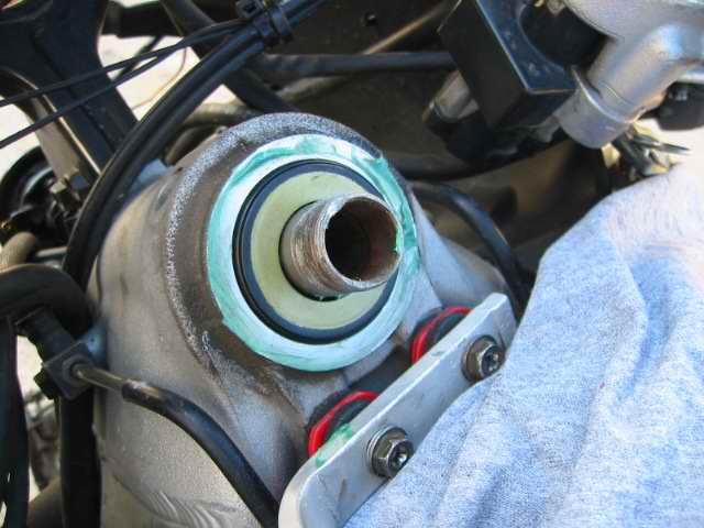
Now the top race
its in, now grease the race surface good.
Pack grease on the new bearings
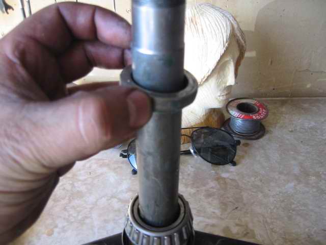
Fit the column back in from the bottom
Make sure the bearings are snug
Put on the top dust seal
I screwed on the flange and tightened it not too tight so that it turned easy but not loose, over tight could ruin your new bearings, too loose and your in trouble. ?It should take about 7 lbs of force to move the handle bar fully assembled you should not feel it grinding thats too tight. ?Just as IntAcepter suggested I followed his procedures for the most part.
Now fitting all the other parts back on, ?I find the bike sits a bit higher now cause they are taller tapered bearings, so the bikes rides a might bit higher. ?I am going to back off some preload first and see how it feels, if it feels like it used to ?I will then lower the forkes about 5mm if the thats the case.</font>
-
3
-
Filter - Clean your K&N, or install
in Maintenance Guides
Posted
Well This Tutorial is probably as simple as a tutorial as can get - certainly there are larger fish to fry but for the cautious member, this is how I do it.
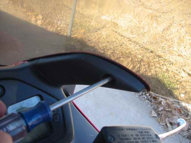
Begin by removing the seat and cowl, this gives the tank room to swivel up.
Remove the 2 tank bolts
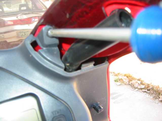
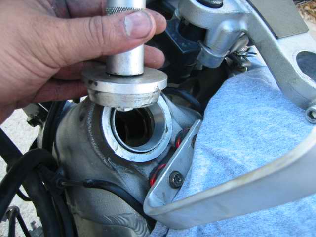
Prop up the tank, if you don't have a good stick you can use the handle and shock spanner in your tool kit, thread one of the bolts back in to keep the tool from slipping off, there is a small hole-in the tank that the spanner sits in.
Remove the 7 screws, you will need a long handled phillips driver the brake lines are in the way.
Remove the flapper hose
Dont lose the wire clips
It is easier if you leave the 2 screws in the top front in as long as you have them unscrewed, that way they wont fall down where you cant reach them.
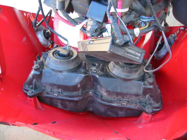
Nasty Dirty filter - I clean mine as often as I change the oil, but I noticed I had a slight drop in fuel efficiency on the trip to South Dakota, I also rode on some dirt roads, my guess was that the filter was clogged.
Remove it and check the pleats for bug that can get stuck inside - sometimes water will not remove insects, I just use an old dull awl to pick them out
Now what to use to clean it? K&N sells a degrease that is recommended, any de-greaser should work, just don't mix cleaning products (ammonia and clorox for example will gas you with chlorine gas) I just use Simple Green detergent in warm water and a big bucket!
The material is a surgical gauze that can get damaged if you use bleach, use something that can cut grease but wont damage the matierial.
K&N Customer Service!
I noticed that my filter had broken and I wondered it was possible to glue it back together, so I wrote them for suggestions.
The filter is actually usable it is just cracked on the backside but still seals up, K&N says they will replace it for me YEA!
Well I put this one back in after letting it air dry, I sprayed some filter oil on it to re treat it, spray side to side not in circles.
If you don't treat the filter with oil it will not be effective, the oil is what traps dust.
I also drilled a new hole for my air temp sensor, the OEM spot is right next to the radiator and it was reading too high.