BSR67
-
Posts
64 -
Joined
-
Last visited
Content Type
Forums
Profiles
Gallery
Blogs
Downloads
Events
Everything posted by BSR67
-
Regulator/Rectifier Upgrade complete - Bike keeps cutting out
BSR67 replied to BSR67's topic in Electrical
100% hard to beat! BSR67 -
Regulator/Rectifier Upgrade complete - Bike keeps cutting out
BSR67 replied to BSR67's topic in Electrical
Hi No, not that was obvious. That said, I wasn't looking for it to be HISS initially. The HISS light lit when the bike came back to life. I stripped the yellow/red out - it had literally broken with a 90 degree bend/kink. They are fine wires. Ended up doing a little solder surgery - I had stripped back areas of the four wires to undertake continuity checks. Ended up splitting all three remaining wires so I could heat strink the areas where I had stripped back the insulation. I then re-sleeved the whole lot to preserve/protect. The good news is, it is fixed now, and I am grateful to you, and others here, for the help and guidance. BSR67 -
Regulator/Rectifier Upgrade complete - Bike keeps cutting out
BSR67 replied to BSR67's topic in Electrical
Hi Grum, DannoXYZ Fixed ....... The yellow red wire on the HISS ring had a break in it ..... I spliced a new wire in and we are all good. Phew! Thank you so much for your help. I can get the bike re-assembled, tested and put it up for sale. Regards BSR67 -
Regulator/Rectifier Upgrade complete - Bike keeps cutting out
BSR67 replied to BSR67's topic in Electrical
There is a lack of continuity in the yellow red of the HISS ring. I'm just about to solder a replacement wire in. BSR67 -
Regulator/Rectifier Upgrade complete - Bike keeps cutting out
BSR67 replied to BSR67's topic in Electrical
I've now fiddled that much that it won't start - but will turn over. I think the HISS wire(s) must now have completely failed. Thanks BSR67 -
Regulator/Rectifier Upgrade complete - Bike keeps cutting out
BSR67 replied to BSR67's topic in Electrical
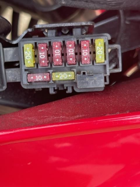
I seem to have found the issue ...... I tried all the fuses Grum - C, E, F. 12.2v at each with the engine off - reflecting the battery charge. Voltage through the black wire ...... 12.2v on the red plug. 14.4v with the engine running. I kept fiddling with the wires at the headstock - narrowed it down to the wires coming out of the HISS loop - if you waggle them, the engine dies and the fuel pump recycles. Basically, it keeps momentarily immobilising itself. Going to repair the wires ......... Will update. Thanks for all you help so far. BSR67 -
Regulator/Rectifier Upgrade complete - Bike keeps cutting out
BSR67 replied to BSR67's topic in Electrical
Hi Grum, Correct - on turning the ignition switch, the fuel pump runs, and the FI light goes out after circa 3 seconds. When the bike cuts, and then comes back to life, the same happens. Thank you for the guidance - I'm at home now so will investigate the C, E, F this afternoon between meetings! I'll test the Black wire as directed. Brilliant help as ever. Thank you, BSR67 -
Regulator/Rectifier Upgrade complete - Bike keeps cutting out
BSR67 replied to BSR67's topic in Electrical
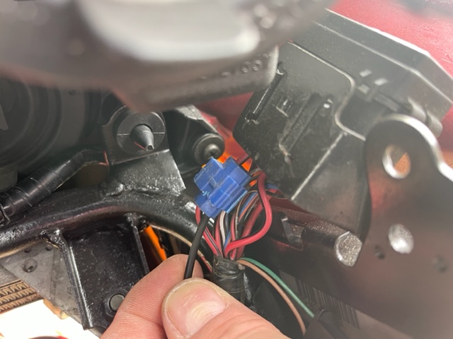
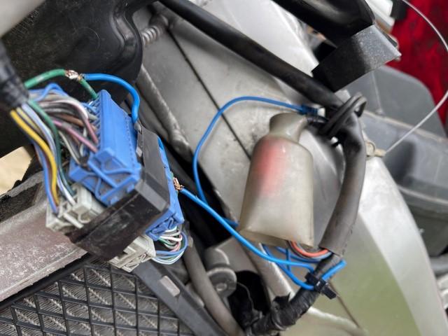
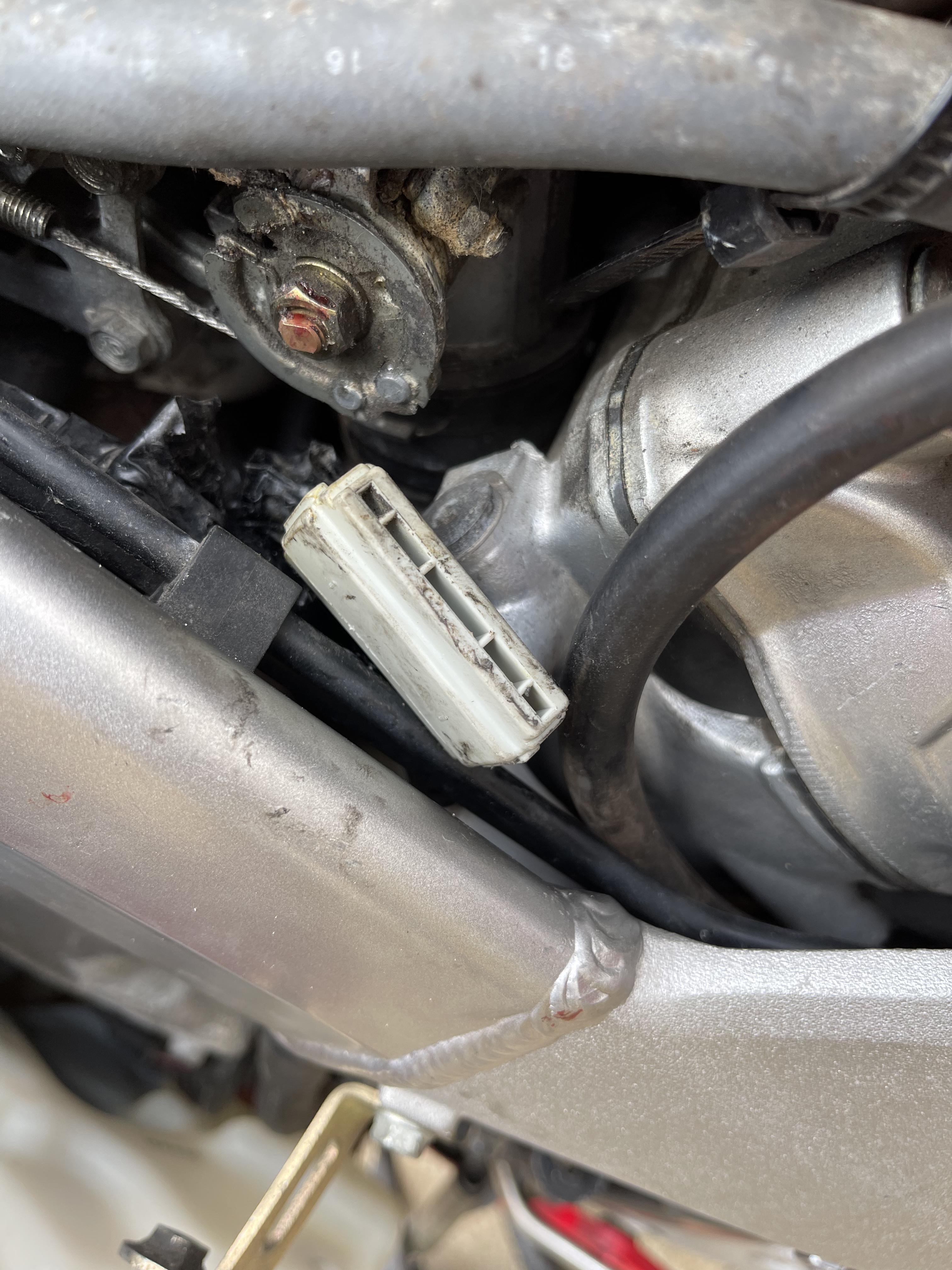
Grum, Danno OK, so I disconnected the heated grips and pulled the fuse. The grips are splicing into a Red/Black wire immediately next to the fuse box - appears to the the 20 Amp Headlight circuit. See questionable blue connector. Bike displaying the same behaviours with the grips unplugged and the fuse for the heated grips removed. Hoping the video will upload and work. Start the bike, turn the handlebars, and it turns the bike off and the fuel pump cycles again. Thanks BSR67 IMG_5563.MOV
-
Regulator/Rectifier Upgrade complete - Bike keeps cutting out
BSR67 replied to BSR67's topic in Electrical
Thank you DannoXYZ. I'll continue to investigate and report back later today. Makes sense it is related to the grips .... BSR67 -
Regulator/Rectifier Upgrade complete - Bike keeps cutting out
BSR67 replied to BSR67's topic in Electrical
Thank you Grum. Great advice as ever. I do know that the grips are spliced into a wire near the ECM - NOT to the battery. I'll check later this morning and report back. Will also unplug the grips. Thanks BSR67 -
Regulator/Rectifier Upgrade complete - Bike keeps cutting out
BSR67 replied to BSR67's topic in Electrical
I've bought a second hand RHS switchgear from eBay .... BSR67 -
Regulator/Rectifier Upgrade complete - Bike keeps cutting out
BSR67 replied to BSR67's topic in Electrical
Just done a little more digging - I suspect it is the loom from the RH switchgear which contains the kill switch .................................. BSR67 -
Regulator/Rectifier Upgrade complete - Bike keeps cutting out
BSR67 replied to BSR67's topic in Electrical
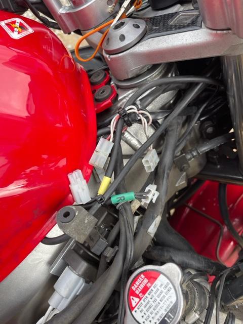
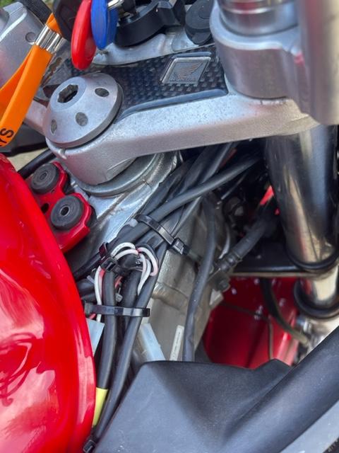
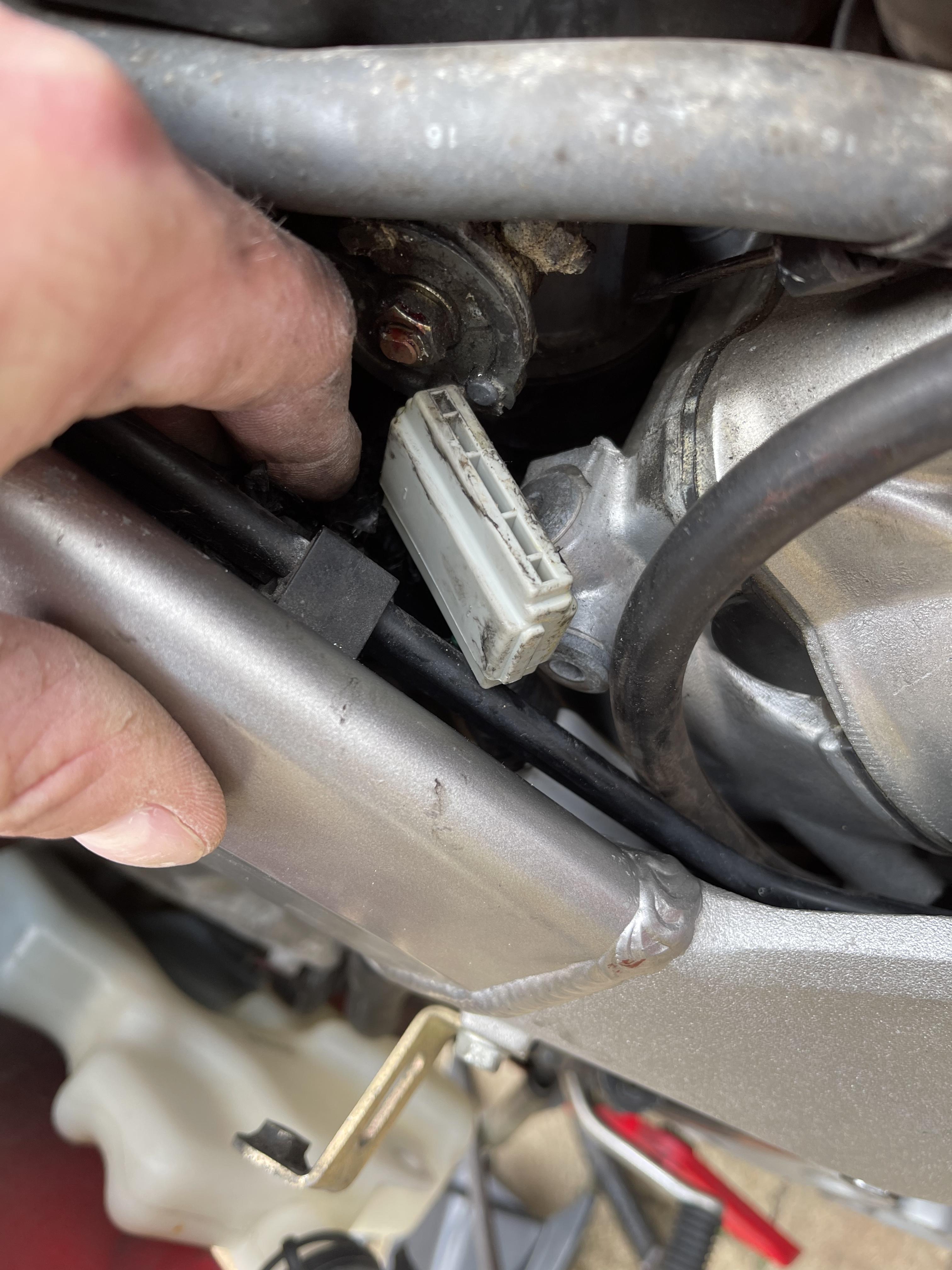
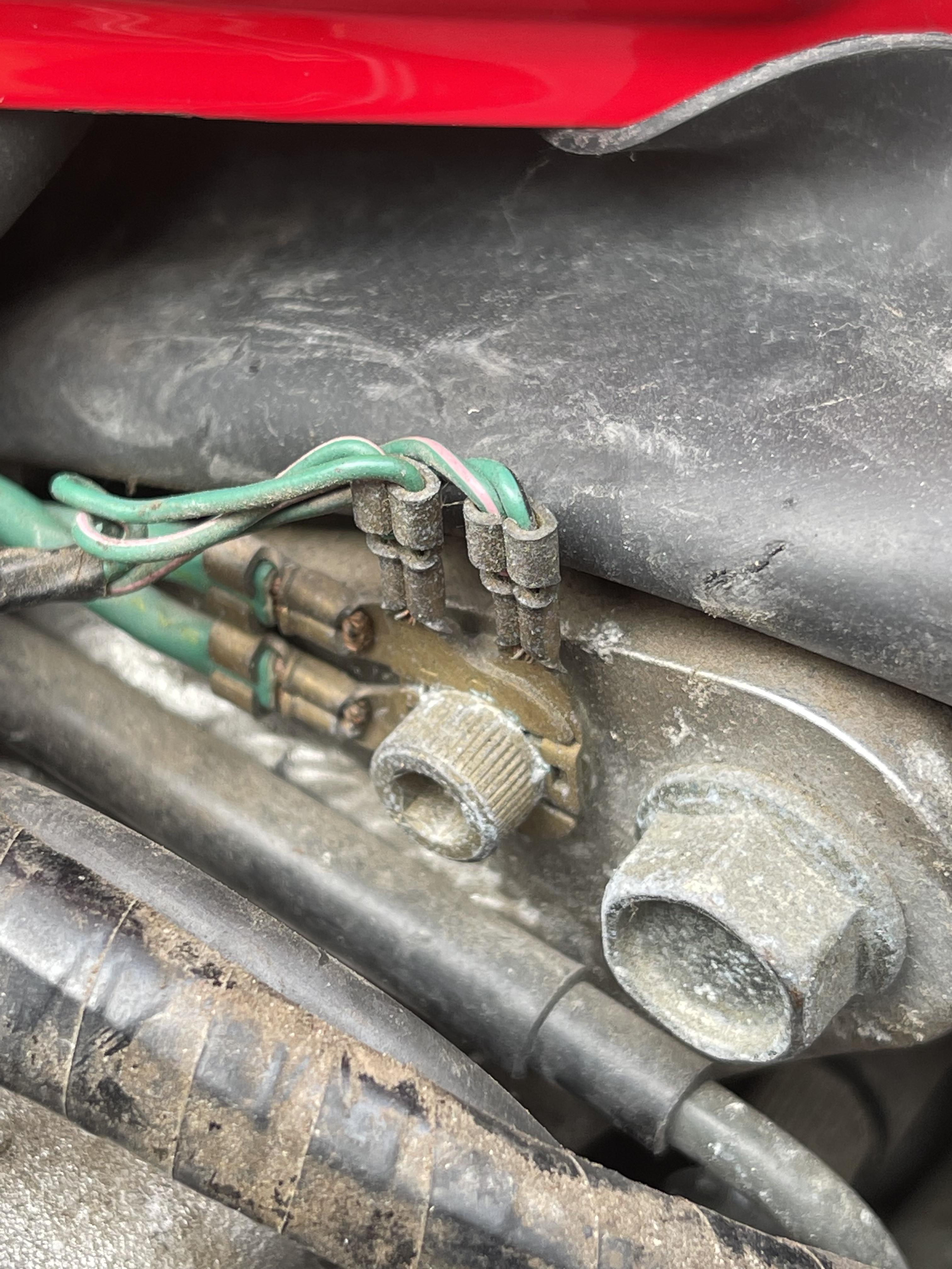
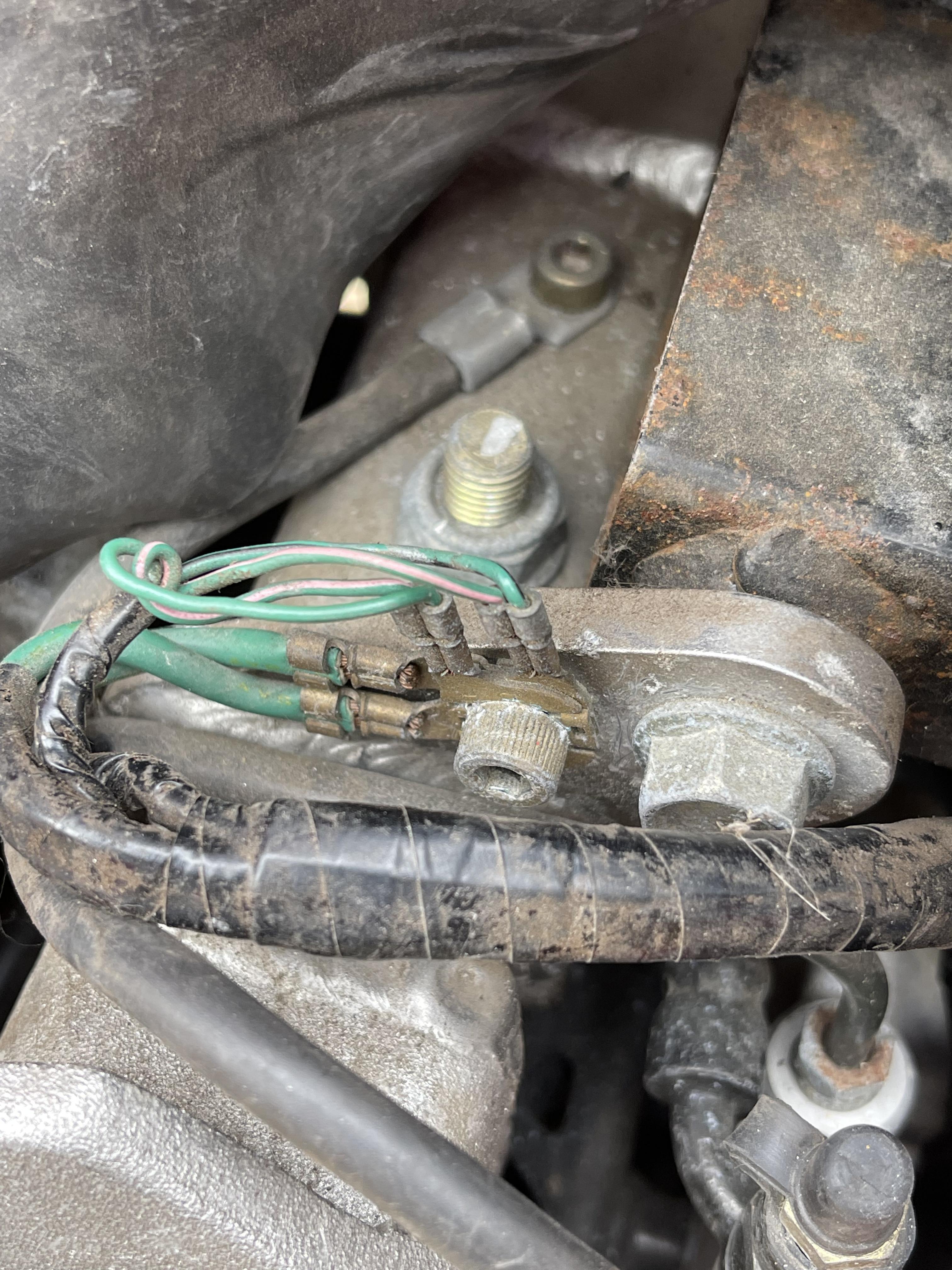
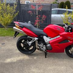
Grum, All, I think I've found the issue. Just prior to undertaking the R/R upgrade, I replaced the 'Oxford Heated Grips' - they had failed. I bought a new set and simply plugged the new grips into the existing sockets from the prior set - as in I didn't have to do any splicing into the loom etc - I just used what had been installed. So, the wiring for the grips has historically been zip tied to the loom at the RHS of the headstock. I clearly clipped all the old zip ties off, took off the old grips, put the new grips on and then re-zip tied. So, now, when you start the bike it ticks over. Waggle the loom where is it zip tied and it cuts out. Then re-start, and turn the handlebars to the right and it cuts out. So, I'm guessing (and that's an educated guess!), that I have a broken wire in the loom where it has been zip tied for years and it will be a power wire to the ECM or similar - which is simply turning the power off. Please see the photo of the 'offending area'! Can anyone advise that colour the wire that is most likely broken is? I sense I am in from a lot of soldering/splicing. If this doesn't fix it, will update. Thanks BSR67
-
Guys, I've just completed the FH020A Regulator Rectifier upgrade. The bike was perfect before I undertook the upgrade - it was producing 14.3v at the battery (and handle bar mounted monitor). I have fitted the upgrade provided by a VFR enthusiast (Kev's Shed - see YouTube) here in the UK. I have hard wired the three yellow wires to the new regulator, and also attached the red and black wires to the battery. The bike is now continually cutting out. It will start and as soon as you try and ride, it cuts out and I have FI light on and then it stall. It feels like a bad earth, but I cannot see how. The continuity of the black wire from the regulator to the battery is perfect. The battery earth is perfect. Has anyone experienced similar? I'm really irritated because I am selling the bike (was!), and only did the upgrade to improve it's saleability. It now doesn't run properly. The cutting out is chronic - it's now unrideable because it cuts out within second, re-starts, and cuts out again. There are no codes for the ECM. Has anyone experienced this? I have, last year, resolved the common earth bar ground issue and also the nose cone (grey) connect ground issue. I'm concerned the ECM has been fried due to the poor earth. This is probably one for GRUM if he is still on here because he was a massive help with grounding issues last year ..... Thanks BSR67
-
Hi Grum, I thought I'd follow up on this, although it is some time since the original issue. I didn't make any earth bar mods for some time - in fact, the bike covered 1,500 miles before it coughed again. Same behaviour - cut out at speed (80mph), instantly restarted, glowing FI light, then brightly on. I checked the EFI codes and again it said both O2 sensors although the heaters. The bike was slightly more haywire - fuel pump running continuously on power up, erratic flapper valve behaviour - generally unhappy. I left the bike almost two weeks, and when I turned the ignition on, the fuel pump kept running and the FI light kept flashing 24/25 despite not having a wire bridging the plug! So, I did the blue connector modification - the one on the left side under the fairing behind the nose fairing, when I bridged the green earth wire with a fresh wire and took this back to a frame grounding point. I soldered the jumper wire in and insulated the connections. I then followed your Option 4 advice Grum and stripped the plastic off the earth bar cap and soldered two wires on to it (the bar is grouped in to 4 and 16 pins), and took both back to the negative battery terminal (academic I know as in effect both the 4 and 16 pins are connected via the common battery ground connection), and I then bound the earth bar assembly up in black insulating tape. So, I've now done a further 600 miles and it has been trouble and gremlin free thankfully, so far (fingers crossed). So the moral of the story is, most people pull the entire grey earth bar assembly off and solder 20 wires together which just felt like a serious hassle. I was fortunate that the 20 pin earth bar plug was in good enough condition to be used - I realise these sometimes melt, necessitating the 'solder all 20 together' option! So, thanks for the great advice, and I hope this is useful to anyone having the same FI gremlins. Alex
-
Thanks Grum. Good advice as ever. I’ve managed 84 miles on the bike without a hitch so far. Will undertake the busbar mod as soon as possible - soldering the group together. Shocks me, as it does others, how undersized and basic the wires and devices are given the load and heat. Thanks very much Alex
-
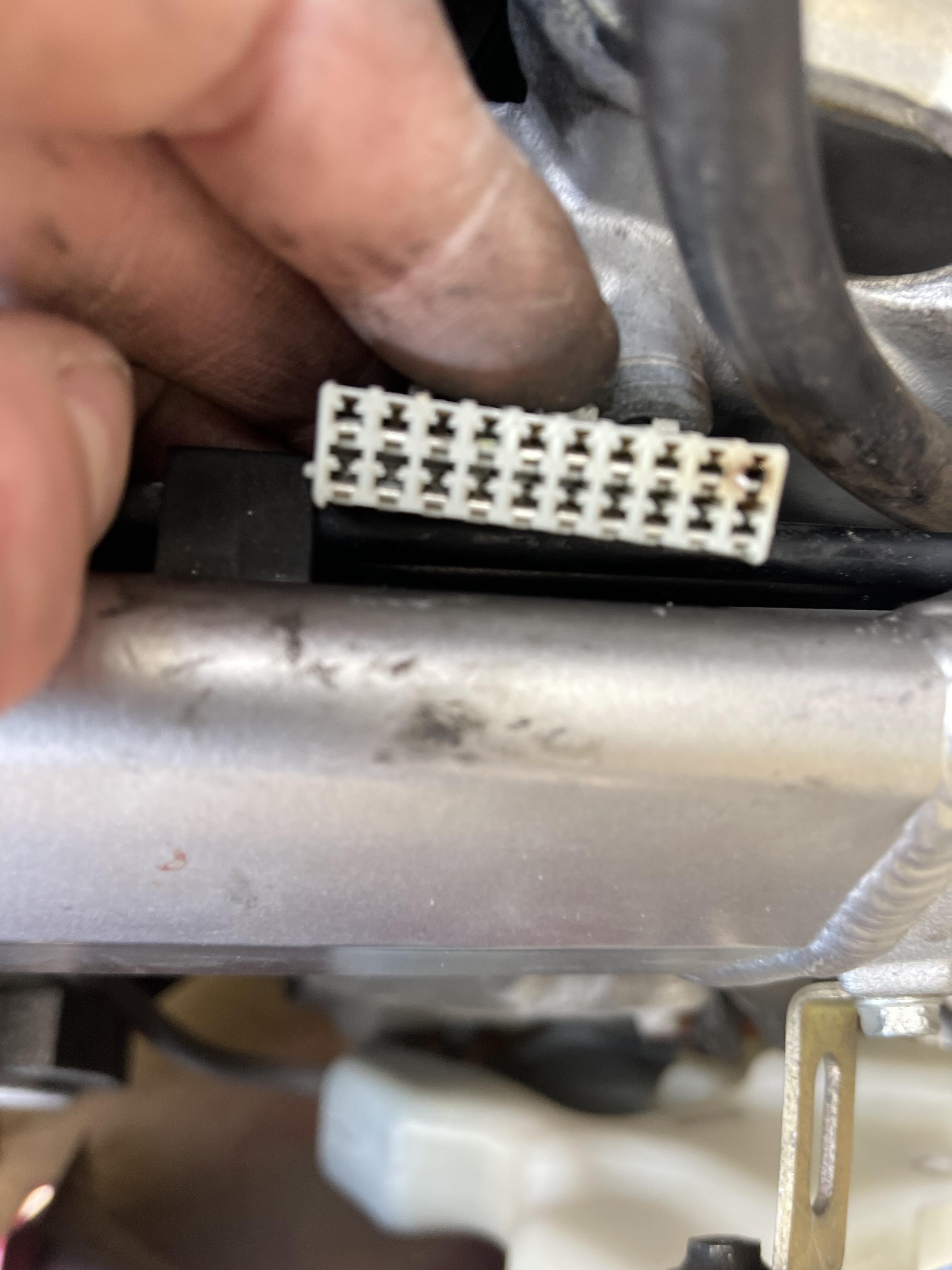
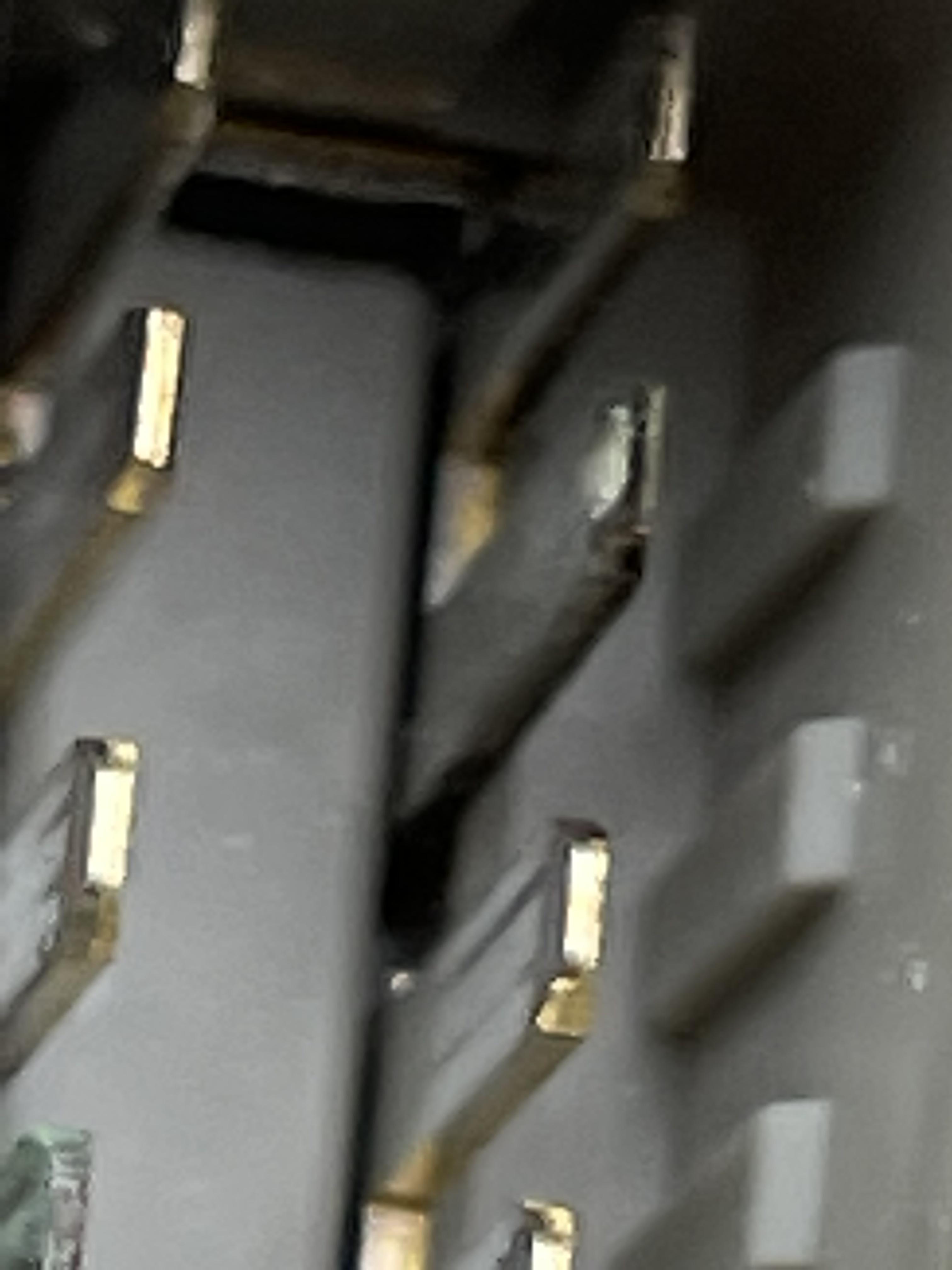
Hi Grum/All It’s a damn shame the video doesn’t work. It shows me running the multimeter along the pins with the black lead on the negative battery terminal which we know is securely earthed. Taking the photo attached here, the readings on the lower row of ten pins working from RIGHT to LEFT are (where on 200 ohms the multimeter reads 0.08 ohms when the red and black are touched together): pin 1 1.0 2 1.3 3 1.4 4 no continuity 5 ditto 6 0.10 7 no continuity 8 ditto 9 0.10 10 no continuity Taking the upper row working from RIGHT to LEFT: Pin 1 (slightly scorched) 0.09 2 2.8 3-10 no continuity So, if in the table above pin 1 (slightly scorched) is the main earth wire, the earth is Good at 0.09 ohms (0.01 off base reading). Pin 2 is 2.8. Is this the culprit? I’ve re-assembled for the time being and plan a test ride. The only pin of concern is upper pin 2. I will report back later - probably Monday. Thanks all for guidance and patience. Alex
-
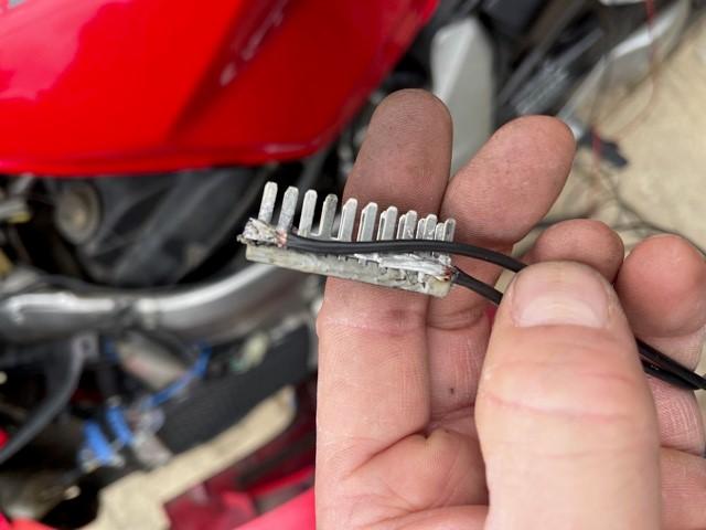
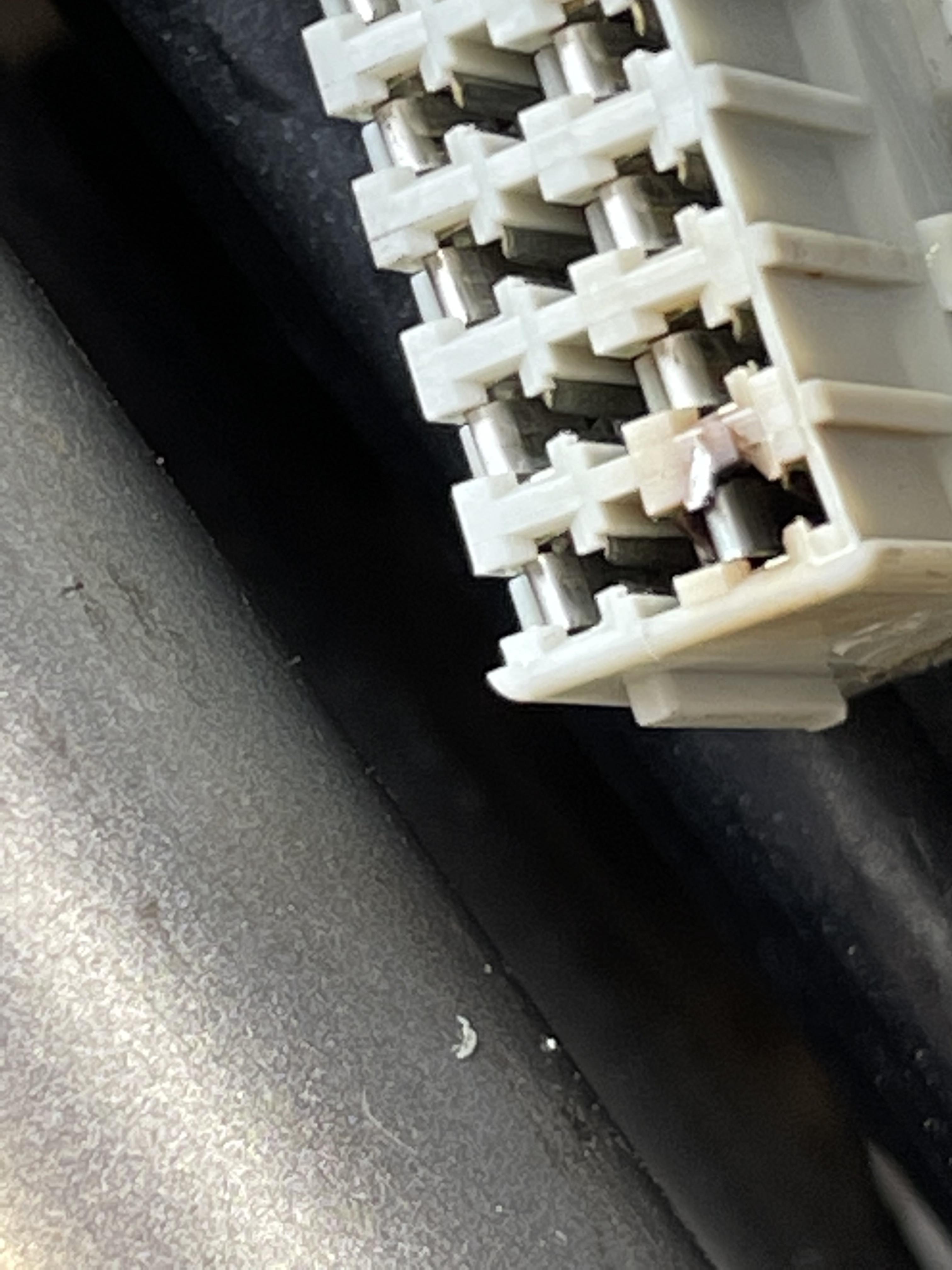
Hi Grum/All This is the busbar. Interestingly there is a natural break between the two sides at the far end of the plug (the opposite end to the main earth wire). You can just about see it in Photo 2. Alex
-
Step 2 Continued. Video checking the pins on the grey ground bar. One side at a time. One connector is slightly higher - the second pin in the second video. Will welcome your thoughts on that second pin and also, the test regime for the ECM to ground. Thanks Grum Alex IMG_7318.MOV IMG_7319.MOV
-
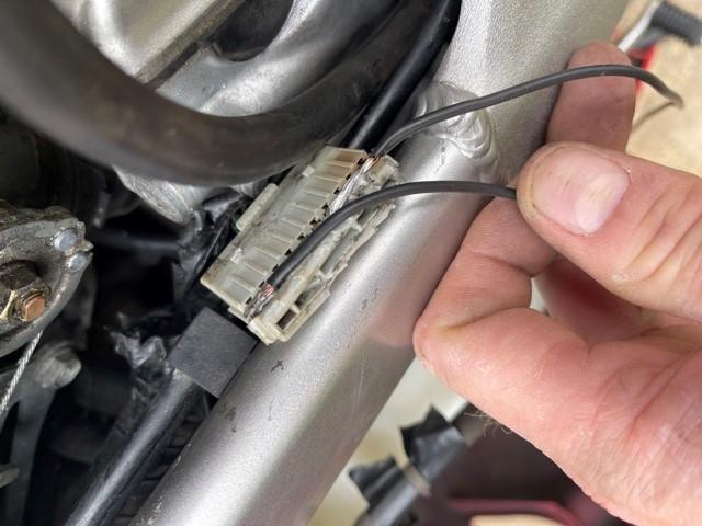
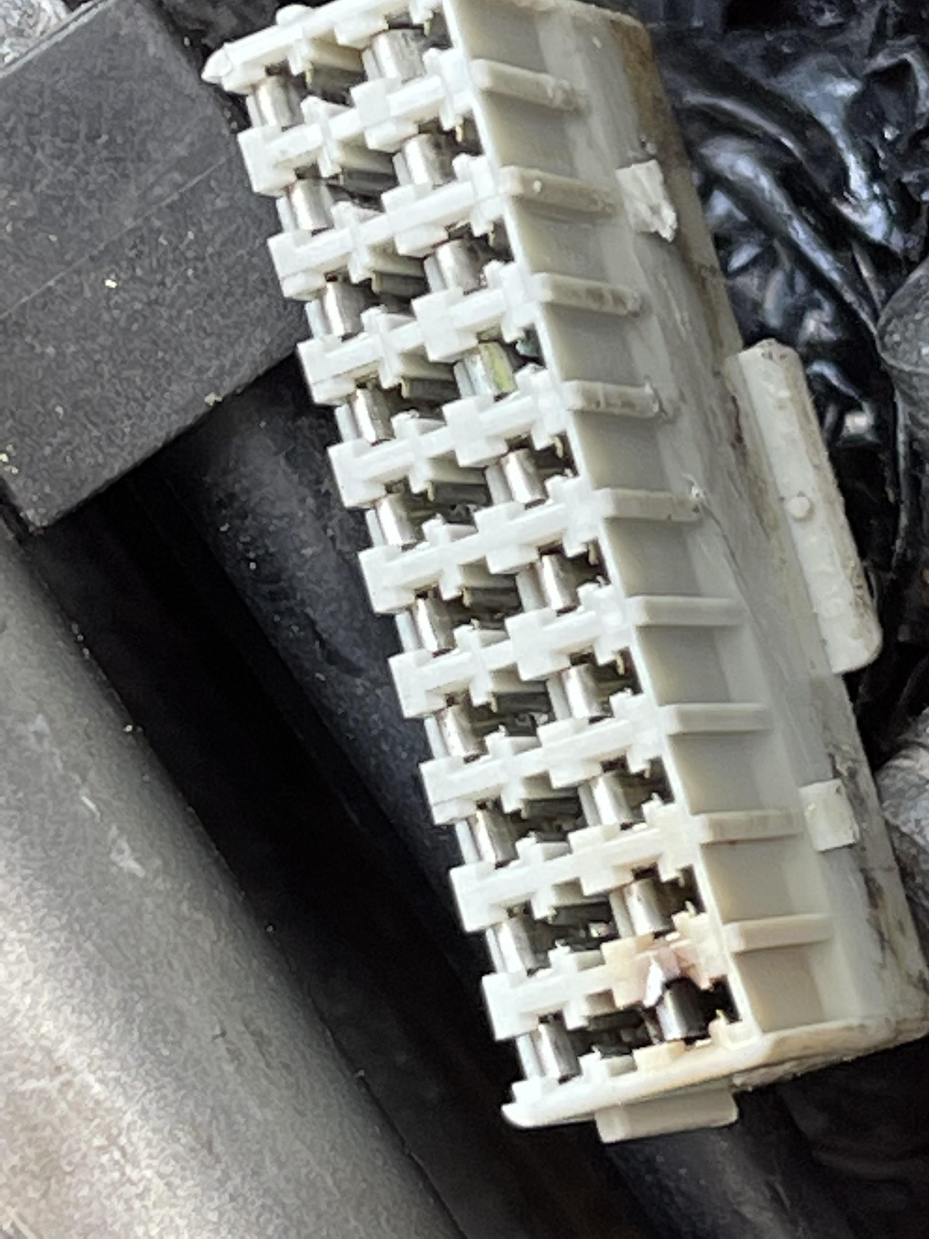
Stage 2 continued. Plug exposed. Some light scorching. The lightly scorched terminals across from one another read 0.08 ohms when linked back to the battery negative. Others give no reading. Some are Differing values. Video to follow. Thanks Alex
-
Step 2 Here is the earth block. I’ve unwrapped it. It is far easier to access from the top. Going to separate the cap shortly. alex
-
Hi Grum A small step. Photograph attached of ground anchor point left hand side of the bike (as you sit on it). It shows the two green/pink wires. Also two further green wires. The second photograph shows the battery ground bolted to the frame cross member. ALL readings (black multimeter lead on battery negative, red lead to anchor bolts/copper/steel connectors and to alloy frame immediately next to the anchor points) are the SAME as touching the two multimeter leads together - on 200 ohm gauge the reading is 0.08 ohms. The ground function is consistent and works. I have cleaned all spade ends and frame mounting points with grit paper as a precaution. All readings are the same at 0.08 after cleaning. The photographs are before cleaning. Thanks Alex
-
Hi Grum I will check the frame grounds later today. Didn’t realise 20 Ohms is sufficient to form a bad ground. I could not see a cable tie on the loom but will recheck. There is just so little slack on it. The plug is bound up in insulating tape, right? Will follow the steps. And understand the methodology. thx
-
Hi Grum I’m going to be reporting back early next week. I’ve investigated, found the plug but only have basic tools here so need to collect a load from home at the weekend to allow me to remove more parts. The plug is hard to access - I need to remove the airbox etc to improve access. Back soon. alex
-
I mean report back! Wish I was having a drink!!!!! 😀 I’ll report back later ….!!!!!! Alex