

Darth Bling
-
Posts
641 -
Joined
-
Last visited
Content Type
Forums
Profiles
Gallery
Blogs
Downloads
Events
Posts posted by Darth Bling
-
-
Did they modify the shock at all? Port job for the valves? New shock oil?
-
Sure. With that setup, I don't see why you shouldn't be able to load up two maps to your PC3: one for economy and one for power. This is possible because the stoichiometric ratio (where you should theoritically get the most power) isn't the same ratio for best economy.
The PC3 cannot change the iginition timing on the VFR. All it does is intercept the electrical pulses sent to the injectors and either lengthens or shorten them. It cannot move them to advance or retard the timing.
Also, race fuel won't do anything for you unless you've got a way to increase the compression in your engine. In fact, you'll probably make less power and get worse mileage with race fuel than you would with regular pump gas. Racer's use race fuel becaues their bikes are modified to make higher compression and thus need the higher octane to prevent pinging and knocking.
-
i'm finally getting around to installing my elka shock on my 2006 non abs. any tips to make the install easier. does the full exhaust have to come off including all the headers???
No, you can install the shock without taking off the headers. In fact, if you've got small enough fingers, you can install the shock without taking off anything major. You'll need to remove the battery and the cover that's surrounds the rear brake reservoir so you get to the upper shock mount.
One tip that I do have is to grab an old dirty sock or t-shirt so you can wrap the shock up when installing it. This will protect it from getting nicked and scratched.
-
...Registering it should be ok, but I’ll have to have someone make sure they see it doesn’t have an exhaust/was converted to electric so I can be excluded from DEQ. ...
Motorcycle are excempt from DEQ testing in the Oregon. The only reason you would need to take a bike down to a DEQ testing center is to get the VIN inspected, but you can have that done at the DMV when you're getting plates for it.
-
I had my front Pilot Road 2 wash out on me about a week ago. Can't really blame the tire though. Keithbob was behind me and he said he saw my front tire catch air after hitting a pothole in the middle of a corner. Once the front came back down, it washed out on me. I luckily saved it by pushing the bike upright a bit and supermotoing with my foot down. :biggrin: I have to say I'm impressed with how quickly the Pilot Road 2 regained traction.
I also had the rear end kick loose earlier that day. I hit a dip in the middle of a corner and my kickstand caught on the pavement. The rear tire stepped out probably about 4-6 inches, but it quickly regained traction nicely.
Besides these two little hiccups (not the tires fault, just mine), the tires perform well all day. :biggrin:
-
It could be a low battery, and turning on the key takes the voltage below the minimum threshold for the display. Charge it with a battery charger and keep an eye on the voltage.
But he didn't say the bike has any trouble starting though. Usually if the battery is low enough to cause the display to completely died when the key is on, then it's probably low enough to cause the bike grief when trying to start it.
-
I was checking out a 2007(or 08?) Triumph Tiger today, and we happened to have a tape measure handy... can you believe that they are not only long enough, but actually longer than the VTEC forks?
Unloaded free length from axle center to top of fork cap: 32 5/8"
Discuss!
Just did some quick research and the Tiger uses the same steering head bearings as the VFR. So, as long as the steering stem is long enough to fit the VFR frame, the swap should be fairly easy to do. :fing02:
Too bad there is no solution to making a match for the back.
There was a topic a while back on Carrazochi wheels, something like that anyway. You'd need a Duc rear axle, but from memory the wheel could sort of match that Triumph front.
Yes, you can order a signal nut 12-spoke Carrozzeria wheel for the VFR. It includes a custom axle to convert the stock VFR hub to accept the signal nut wheel. Coyze is a dealer for them and his prices are good.
-
Sound like somebody forgot to latch the bag down complete.

-
You can check David Silver Spares. The 2007 VFR red we got here in the USA was available in Europe in 2006. Maybe they have some in stock.
I contacted them to ask about the bags. They asked for the color code, and when I sent it the response I got was that they never got that color over there. I'll give it another shot.
Give them this part number: 08L52-MCW-890. It's the Europeon part number for the bags.
The USA Honda part number for the bags is: 08L52-MCW-1G0
Good luck!
-
You can check David Silver Spares. The 2007 VFR red we got here in the USA was available in Europe in 2006. Maybe they have some in stock.
Another option would be to buy some ultra cheap bags from David Silver Spares and then take them over to Road Trip Essentials in Hillsboro. They do a lot of trim pieces for the Honda Goldwing so the guy has access to lots of Honda OEM paints. He may not have an exact match for the 2007 VFR red , but he'll probably have something close. His painting quality is very, very good.
-
Hey all,
I was just wondering about rain gear.....I know absolutely nothing about the stuff. What features should I consider before purchasing? Any particular brands? Thanks for your input.
Well, you've got two options basically.
You can buy dedicated rain gear that you can put on over your gear to protect you. Rain suits tend to provide the best rain protection, but you've got to carry around the gear with you. If you wear leathers full-time, a rain suit would probably be your best bet. I've also found that in a pitch, you can wear your rain suit as a wind-blocker which will help you stay warm when the temperature drops.
The other option is to wear textile gear that has removable rain liners. I've got a bunch of Tourmaster jackets and they do a good job keeping me dry in the rain. The removable liners are nice since they pack smaller than a dedicated rain suit. Plus, the rain liners are also nice in the cold as they provide an addition layer to keep you warm. Lots of these removable liners are also very breathable too (unlike most rain suits).
I've got Tourmaster (aka Cortech) jackets and they work very well. My Joe Rocket Alter Ego textile pants also work very well too. Any good decent pair of riding boots should keep your feet relatively dry. For gloves, you'll probably want to find some dedicated rain gloves, or not worry about it.
-
As I got hit with a heavy rain storm Sunday afternoon, and every cold big drop caused fog on the inside of my faceshield, I wondered why I have never seen a heated faceshield?? My old Land Rover Discovery II had a heated windshield, and you could hardly discern the elements that did the work.
Surely this would be a great product that people would actually pay up to have. IS there such a thing around?
John
Yes, there is such a thing around.
Snowmobile helmets have been coming with heated visors for some time now. HJC for example makes one: http://www.helmetcity.com/page/HC/PROD/HS1/hjcsnowshields. And, the HJC snow helmets are DOT approved too. http://www.hjchelmets.com/prds_snow_clmax.htm.
Do a google search for "helmet electric shield" and you should get some hits.
-
Maybe this thread will help: http://www.vfrdiscussion.com/forum/index.php?showtopic=41261
-
Turn the key on, everything lights up okay. Hit the kill switch, and the fuel pump primes as normal. Hit the starter button, and you can hear it try to turn over, but the dash goes dead, and it's a no go. Clock and trip reset.
Sound like a dead battery to me.
Remember, if your getting a jump from a car, make sure the car is turned off. If the car is running, the alternator can pump out too much voltage for the R/R on your bike to handle.
-
I'm thinking production numbers and greater availability of the newest models will make them appear more "popular". But its not an accurate poll for popularity.
The poll should really read, "If you could own any Gen, which one would it be?"
-
Just for kicks I grabbed an 18t. I had to grind on the case saver plate to make it fit. I'll admit that I like the change. As soon as just riding around the neighborhood I noticed that I don't have to shift as much as when using the 16t. Also, low rpm chugging no longer gives that chain slapping sound off the swingarm, as it appears that the larger sprocket holds the chain off the guide or some ?. Riding towards a radar sign shows that my indicated speed is now a bit lower than actual. I guess that I like it most in that I don't feel the need to shift so much. Feels smoother too.
At the least, I would recommend to others to toy around a little bit with the final drive just to feel the difference.
Dang! An 18-tooth front?! That's crazy. :warranty:
With the stock 16-tooth front, I've found that the VFR will top out at around 147 mph (calculated actual speed, not what's indicated). With the 17-tooth front sprocket, I actually achieve a higher top speed in 5th gear instead of 6th (at least with saddlebags and a top-box on at the time). Top speed was 136 mph or so.
With the 17-tooth front, 6th gear is definitely overdrive. I have found myself needing to shift down into 5th when going up steep hills on the highway. While I would recommend the 17-tooth for those looking to extend the legs of the VFR for touring duty, I don't think a an 18-tooth front would work quite as well. JM2¢
With the 17t, the speed is indicated almost correct I would think, or is there still a difference?It's really, really, close. The speedo only reads about 1 mph high when riding at highway speeds.
-
How much did they cost from David Silver Spares?
Thanks, Marco.
It depends on the color. Right now, the cheap ones at David Silver Spares are £225. This is about $450 dollars. Shipping is also usually quite reasonable too, only about $200 or so from the UK I think.
I believe the total for my bags when I order from David Silver Spares a few years ago was about $450 for the hard bags, $450 for the top-box, $130 for the saddlebag and top-box liners, and $200 for shipping.
-
I went through Death Valley a few weeks ago with one of those cool vests from Cycle Gear. In addition to wearing a CoolMax shirt underneath and a mesh jacket on top, I was very comfortable.
When I put the vest on, it was about 95°F or so. Once I got moving down the road, it seriously felt like it was 50°F out. I was actually a little chilly. After about 30 minutes the vest dried out. I'm sure if I had the panels in my jacket installed (to convert it back to a regular jacket) and just opened the vents, the vest would of kept me cool longer. Or, if I had put my reflective vest back on over the mesh jacket, that probably would of allowed the vest to last longer.
Either way, the vest is very nice to have in +90° weather. Just be ready to pull over every 45-60 minutes to resoak the vest. JM2¢, YMMV.
-
Where's the asphalt option?
:goofy:
-
I had a custom set made by Now Hear This while at the Cycle World show a few years ago. This was the best $75 I ever spent (other than that one time in Boston's Combat Zone). They work great and have held up perfectly. They're all-day comfortable and they absolutley kill wind noise. :unsure:
:pissed:
Got myself two pairs of Now Hear This custom earplugs at the Cycle World show in Seatle last December. I absolutely love them. They're rated 29 DRR (not quite as good as some 33 DRR form plugs, but at 29 DBB they are more than adequate). They're super comfortable and take only a few seconds to put into your ear once you get the hang of it. I've worn them as long as 16 hours in a day and they never hurt my ears. :goofy:
-
Just got back after riding 4000 miles on my new Pilot Road 2 and so far I love them!
There are wearing very well and they provide some serious traction when lean over. I actually managed to drag my hard bags around a few corners with the Pilot Road 2. :ohmy:
Coming from Pirellis and Metzler tires, these tires feel quite a bit difference. The sidewalls on the Michelins are softer than the Pirellis or Metzlers. They sort of have a vague feel to them until you start to pushing them. The turn-in is great on these things as I often find my lines are too tight in corners. They have a tendency to fall into corners, but it's nothing you can't get use to.
-
Not sure if Jeff is a member here or not, we have several Jeff(.......) usernames on file, but I remember him from the "Big List".
Anyhow, here be the link with instructions:
Cool. Pictural insturctions are the best. :warranty:
I do wonder though why he removed the metal screen just to reinstall it later. I'd probably just skip that step and leave the metal screen in place.
I may have to do something similar to this soon.
-
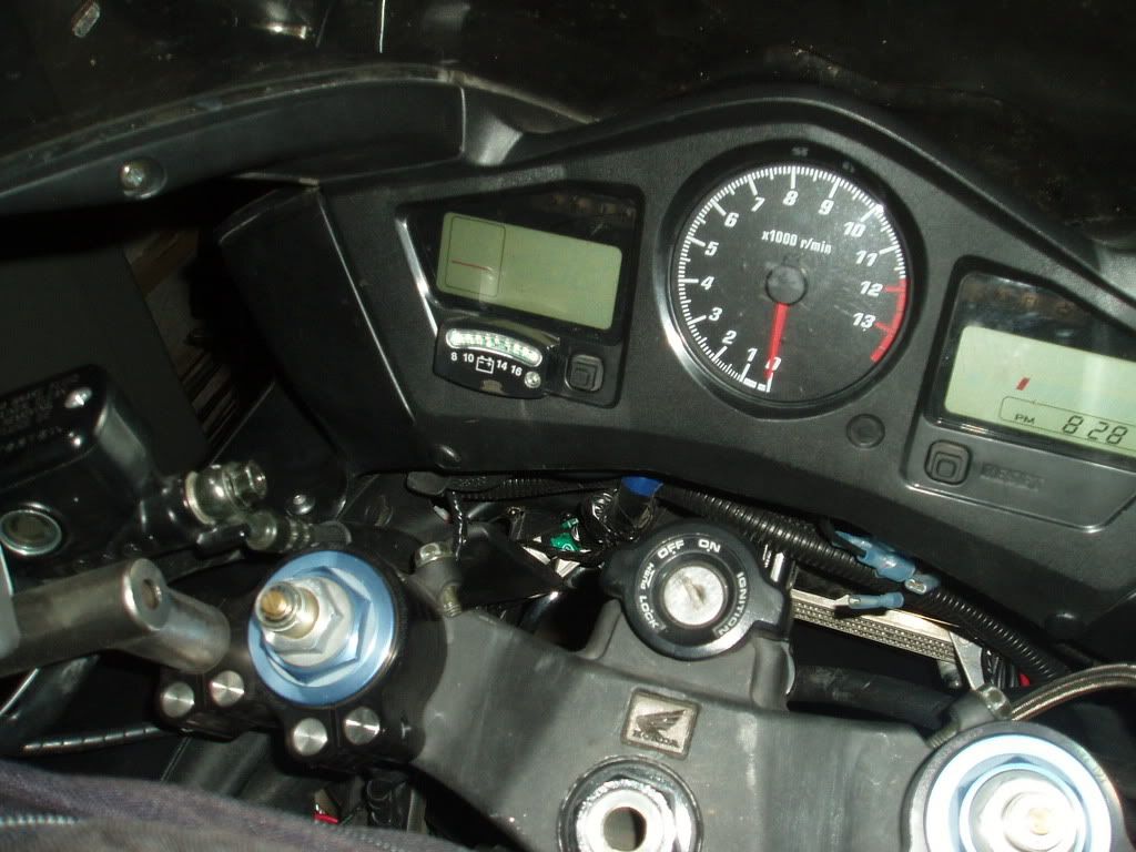
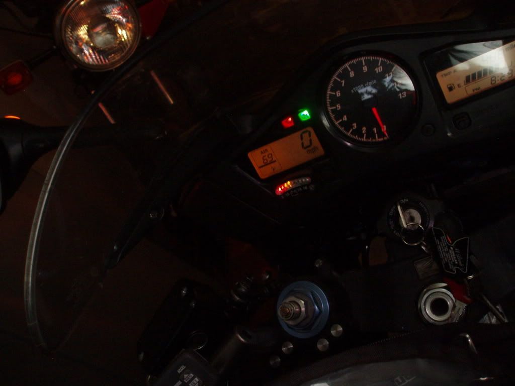
Kuryakin makse a nice looking voltmeter: http://www.kuryakyn.com/products.asp?bn=harley&ci=2695
Some pics of it installed on my bike:


In has a light sensor built, so it brighter in the daylight but dims enough at night not to blind you.
-
Can you fit a helmet inside the liners when they are inside the side cases?
I don't know, it would be close.
Must helmets nowadays come with a free helmet bag. That's really all you'd neet to protect your helmet while it's in the saddlebag. If you buy that new shark helmet, it will probably come with a free bag.
Homemade Manometer
in Modifications
Posted
There's no need to remove the tank completely. Just have to prop it up.
Taking the air box off the bike is pretty straight-forward. The only hard part is getting the MAP sensor unpluged underneath the airbox.