Coxylaad
-
Posts
43 -
Joined
-
Last visited
-
Days Won
9
Content Type
Forums
Profiles
Gallery
Blogs
Downloads
Events
Everything posted by Coxylaad
-
Naked VFR (Old thread archived again 😒)
Coxylaad replied to Coxylaad's topic in Seventh Generation VFR's
Question - does any manufacturer do silicon hoses for the VFR1200? -
Naked VFR (Old thread archived again 😒)
Coxylaad replied to Coxylaad's topic in Seventh Generation VFR's
Progressing. Slowly. -
Naked VFR (Old thread archived again 😒)
Coxylaad replied to Coxylaad's topic in Seventh Generation VFR's
Rear reservoir bracket: neat, even if I do say so myself -
Naked VFR (Old thread archived again 😒)
Coxylaad replied to Coxylaad's topic in Seventh Generation VFR's
Exhaust on fairing on, sort of I’m going to mount the rear brake reservoir here: Fired it up this afternoon too -
-
That's perfect much appreciated grum! Just out of interest, is there any special bleeding procedures for the abs unit?
-
Hi All, Does anyone have, or can get a picture of they abs unit for which shows which pipes go where? Im looking at fitting my abs unit to the project bike, but only the front wheel, and I need to know which is the in and out for the front circuit. Hope someone can help me, the internet is coming up a blank I basically need to know which is the feed in from the front brake lever, and which is the output. I suspect there might be a couple of outputs, maybe one for each caliper on the front.
-
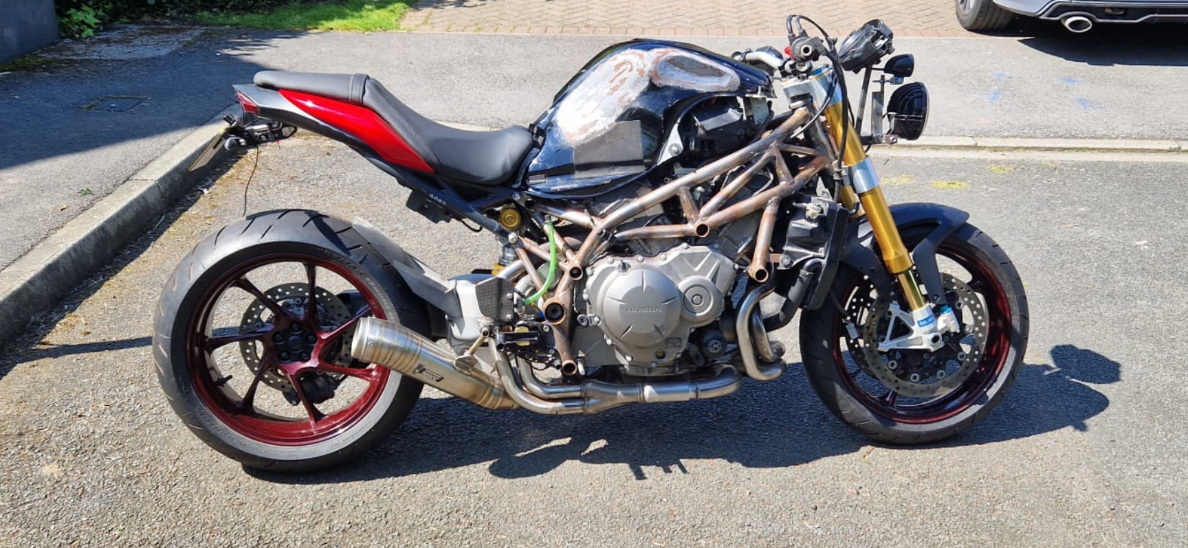
current status:

-
The last picture you may have noticed that the bike is missing a rear shock, Thats becuase it was away getting the correctly rated spring fitting to it. Its back, now with a 180nm spring on it. fitted back to the bike Im adopting a suck it an see approach with the damping. The spring rate has nearly doubled on the shock, so I need to see if the adjustment on the damping can cope. If it cant then the shock will come off and new cartridges will be fitted. Not the end of the world as TTX shock damper cartreidges are easy to swap around.
-
Update: Sorting out the details from the back to the front. rear indicators: I bought some BMW LED indicators, that look nice but the fittings are flimsy plastic and i wasnt happy with them, so I decided to upgrade them. flimsy removed the fitting, drilled it out, and tapped an 8mm thread into it Took an 8mm stainless bolt and drilled the centre out of it on the lathe, then chopped the head off it then threaded it into the plastic part, nice and snug back together, new and improved Next job, seat release mechanism. I kept the vfr seat lock, and acquired the Speed triple seat release mechanism, Need to mount the VFR lock and mate it up to the S3 mech. VFR lock: S3 seat release mech bracket to mount the lock in the hole and stop it turning: Its industrial, but it wont break 😀 new arm to take the end of the pull cable - I used a 10mm bolt, drilled a 8mm hole in it, then slotted it to take the nipple Removed the arm from the VFR lock, flattened it, and trimmed it down, then welded the 'nipple holder' on (he said nipple 😄) Needed some dressing at this point, but thats the last photo I had of it Modified the lock mounting bracket so it holds the pull cable outer in place et voila, sorted, and another job ticked off.
-
little bit of progress: Number plate and rear indicator mounting done. You cant see the bracket underneath but it took me 2 hours to make haha
-
Wiring work at the weekend. need to get it tidied up and fixed in place. I need to get some more photos up but Ive made the headlight bracket and fitted that
-
Update: Got a bit of time whilst everyone was watching the queen so jumped in the garage and picked a job to do - Exhaust hanger: Started with some stainless tube and a stainless nut bashed it in with a hammer Chopped the tube down, then done the same again to make the end fixing pieces of the bracket. here they are bolted in place Then took a smaller diameter stainless tube, cut to length and shaped to fit the odd interface angles, then welded up: I also welded in the nuts around the seam so no chance of them working loose (not that they could based on the force needed to press them in) Finished, apart from a bit tidying of the weld up. All stainless so doesnt require painting. Massively overengineered, just the way I like it Another job ticked off. I think the next job will be to tidy up the wiring and sort out a battery box for under the seat.
-
bit of an update: I dont get a great deal of time to work on the bike these days but Ive managed to get a few things ticked off: Needed a big earthing point for the loom, so I welded on a small section of 6mm steel onto the cross tube under the tank: Drilled and tapped: All mounted up: So Ive been looking for a bit inspiration and motivation to get moving with the bike, what more motivation than hearing it fire up for the first time! went through all the wiring connecting everything up and making sure it is how it should be. Its a bit of a wiring disaster at the moment and required a lot of sorting out, however the good news is that I got it running on the first time of asking! (well almost - I forgot to connect the fuel hose up and fired petrol across the garage floor when i turned the ignition on) Anyways video evidence: Interesting to hear the throttle bodies cycling through with no airbox or filter on. I was wondering if it was something to do with the fact they have been unplugged for over a year and they might need balancing or something, or thats the noise they make and you normally cant hear it becuase they are burried under all the plastic and ducting. Happy days. time to start tidying all the wiring up!
-
Ah its ok, Ive just a picture, its written on the regulator!
- 1 reply
-
- 1
-

-
Does anyone have a picture of their regulator so I can work the wiring on mine? I took a picture of mine when i removed it from the bike, but that was 2 years ago and I cant find it anymore!
-
much appreciated, Ive ordered a couple from these guys - https://www.motorcyclespareparts.eu/
-
Hi All, Been a while since I have posted anything about my ongoing project bike - so long that my original thread has been locked and I cant get back into it anymore 😞 Ive messaged the admins but i never seem to get a reply. Anyways, its been a while, mainly because I have moved house. Even after I moved its taken me a long time to get my garage into a position where I could actually do any work in it! some pics to kick off again: In its new home: Ive discovered a great way to make short work of polishing headers. Using my powerfile with an old sanding band in there is abrasive enough to remove the corrosion and tarnishing from the headers, without actually touching the metalwork: headers modified, link pip welded up and exhaust in place: Ive made the bracket to mount the main header and collector box to the botom of the frame, but I never took any pics of that. I will do that later. I have the exhaust hanger to fabricate,, but as soon as my exhaust gaskets arrive I will be moving onward to the next Job. I looking for a bit of inspiration and a motivation, so the short term objective is to the get the bike fired up and hear it running for the first time in a couple of years.
-
yes number 13. do you know dimensions of them?
-
Hello everyone, Its been a while since I pulled the old VFR apart to start my project, I am fitting the exhaust back up, but I had removed and disposed of the 2 graphite exhaust gaskets that go in the join between the rear header pips and the rest of the collector, behind the RH footpeg. I need to buy some more, anyone got a link, or got the dimensions so I can source them please?
-
Hi everyone, Looking on ebay you can get a set of Delkevic headers for a crosstourer, I noticed they dont have the big loop around the front at the bottom. anyone bought a set and tried them on the VFR1200F?
-
progress update: decided to order myself a set of custom yokes instead of messing about trying to make things fit. They took 10 weeks to arrive, but they were worth the wait. Very impressed. The fit of the ignition barrel is absolutely perfect, it even includes the fittings for the transponder ring that sits on top of it. very happy Stuck it in the freezer overnight, and fitted the bottom bearing: Trial fit up: fitted to the bike: I need to do some more work on that airscoop, but that can happen later.
-
yes! thats kind of what I was going for. big aggressive airscoops
-
not done a great deal on the bike itself, but i have done a fair bit of 3d modelling. i was reasonable happy with the radiator side panel, its done apart from a few little tweaks. the next job was building some airscoops to fill the huge hole under the fuel tank. To do this I have had to learn about forms with fusion 360 (previously i have just modelled solids) Forms are a lot more fluid, and used when you dont have any specific straight edges/dimensions you can put a ruler against. So. to do this I first needed to define the contact edges of the of the tank and the frame where the airscoop will sit. In the abscence of a £10,000 3d scanner I used a technique called photogrammetry, where you take a load of photos of the object you want to scan from all avaiable angles, then you feed them into some software and it creates a 3d image of the bike that you can play with. Here are the results: from there i stripped away the unnecesary parts and left the surfaces I need for the airscoop, which is the top rail of the frame and the bottom lip of the tank. Then I exported it as a dense point cloud into fusion 360. In fusion 360 I could then plot a T spline curve alone those edges which defined the edges of the airscoop. I then mucked about with surfaces in forms until I got this: This was the first printered iteration, I am on verion 4 or 5 now, and it looks something like this: Couple of flat spots on here I need to sort out on the next print. how it hangs together with the radiator in place: over all I am quite pleased with hows its going, not finished yet, but it should look fairly factory (ie not nailed together in a shed) once its done.
-
much appreciated. is that an US site or can you order from the UK?