N8sVFR
-
Posts
147 -
Joined
-
Last visited
Content Type
Forums
Profiles
Gallery
Blogs
Downloads
Events
Everything posted by N8sVFR
-
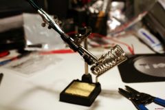
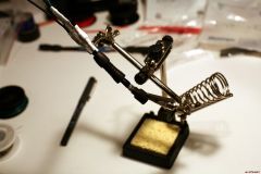
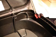
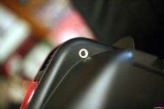
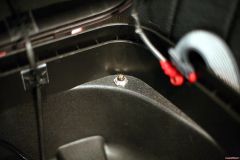
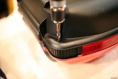
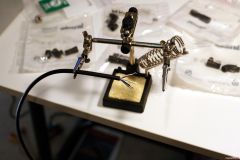
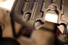
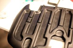
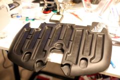
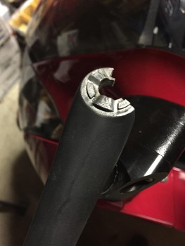
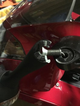
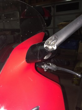
Ok guys. . . here are the photos that should help. First image: snapped off stock GSXR mirror stalk at the base. . . .note the flat head Phillips bolt. If you google 'flat head phillips' you will see that this type of bolt or screw actually has a flared bottom. It's not flat on the bottom. . . .it's flat on the top!!!! You have to know your bolts. . . .you should be able to see how tightening the bolt further, essentially results in you forcing a funnel shape into a cylindrical hole. . . .the tighter you make it, the more outward pressure on the cast metal until. . . .SNAP. And then you are left with this: Next image: bolt unscrewed so that you can see the flare on the bottom of the bolt, and the detents on the bottom of the GSXR mirror stalk. . . more on that in a minute. Last image: a clearer shot of the detents. Yes, they are rather small. But, when you take apart the stock GSXR mirror base you will see how these are intended to work. There are actually spring washers in the factory assembly which apply pressure into the joint. The detents mate up, and keep the mirror stalk from spinning, falling either forward or backward. The true beauty of this is that you CAN intentionally fold the mirrors back without fear of either over-tightening or loosening the bolt in the process. If I were recreating these mounts, I'd find a way to incorporate the detents in the newly machined base, and find a more suitable bolt which would not create outward pressure and would allow for the incorporation of the spring washers. . . . One more thing. . . .don't be thrown off by the fact that I have the Lobstender mirror extenders too. I wanted to get the mirrors farther out since I installed the top-mount luggage as well. Those have held up well over the years. . . .
-
From the album: GSXR MIrror Adapters
-
From the album: GSXR MIrror Adapters
-
From the album: GSXR MIrror Adapters
-
I'll have to be more specific. . . .I'll try to get some photos tonight. Yes, mine were just like that, and yes, mine had the phillips countersunk screw / bolt. That was the problem. Pictures will speak 1,000 words. . . . The detents I'm recommending would be at third points in the bottom of the circular recess already milled into the mount. The stock GSXR mirror stalks have protrusions that keep them in a relative position. . . .like I said, more when I have some pictures. -Nate
-
Seb - simply beautiful. Marvelous machine work, glass and carbon fiber work. You've managed to merge all of the stock bits along with your custom fabricated parts into a GORGEOUS machine. I tip my hat to you, Sir. :)
-
Greg -- not sure if this will be helpful or not, but I have a set of the original production run of the GSXR mirror adapter mounts installed on my '02. One of the problems that I've had with them over the years was the approach of using a flat head phillips bolt for attaching the mirror to the new mount. The problem with a flat head bolt is that it puts outward (not downward) pressure on the cast aluminum GSXR mirror stalk. A bit of over-tightening and . . . . .snap!! The mirror stalk will split or break in a couple places at the mounting hole, rendering it useless (which has happened to me). I was also not a fan of the fact that the aluminum adapter mounts did not include detents in the recess where the GSXR mirror stalk actually mates up with the mount. There is essentially nothing keeping the mirror stalk from rotating on the base with the exception of the friction created between the stalk and the mount by the flat head bolt. . . . .and I already pointed out the problem with that design above. When you try to tighten the bolt to ensure no rotation, the hole in the mirror stalk cracks. So, in short, you might consider utilizing a different type of bolt that won't put outward pressure on the cast aluminum stalk, and ideally, adding detents in the new adapter mount to mate up with the mirror stalk. Just my $.02. I can take some photos tonight if that would be helpful. . . .not trying to be a downer AT ALL (I love the GSXR mirrors on my bike) but I think that these minor changes would make a significant difference. -Nate
-
Hey guys - glad to see that this old post is still getting some mileage!! Awesome to see what others have done to improve visibility and safety. If I had it to do over again, which I might some day. . . .I would probably go with a slightly different system utilizing relays instead of the diode and resistor technique. I believe that I've gotten some loss of power over time due to natural decay of the performance of the electronics that I chose to use when doing the original build. The LED's aren't quite as bright as they were originally, either due to natural reduction in performance over time of the LED's themselves, or the resistors and diodes.
-
Tightwad - The SMLED's that I used were the brightest that I could find in a red SMLED that would fit behind the reflectors. I was actually pretty pleased with the brightness - easily visible even in full sunlight. Perhaps the video's and photos don't do the lights justice. I'll have to work on that. The reflectors also help to spread the light from the LED's over a greater area as well. Binder connectors rock. Great quality, selection, and super service. Couldn't ask anything more from them. My limited understanding of wiring for control of the LED's would require individual wiring to each LED or groups of LED's that were to be controlled separately. That would be a ton of wires to pack into the topcase, and coule be great for looks, but would defeat the purpose of the topcase for me -- room to take stuff with me!! My setup is obviously specific to the OEM topcase. You are absolutely right that other cases would require specific / custom installation and fabrication. Honestly, I was shocked that I couldn't find anything out there that was already being manufactured and I just wanted to put this out there for anyone who has an OEM case so that they would know that it was possible. It's not a cheap proposition, but definitely worth it for me. When I was first fabricating my lights, I was thinking about going into production if there was enough interest. It has taken forever for this topic to even reach two pages, so that idea went out the window pretty quick. There are economies of scale of course - buying in bulk would bring the cost of the parts down, but not that significantly (I was thinking 15%).
-
I did use a reduced feed or the running lights, in-line resistors, as you suspected. I ran the calculation and came up with the ohm-rating that I needed. I'll post that up later. I can get you a pretty complete parts list too, but it will take a bit of time. I can probably pull it all together sometime this weekend.
-
Yup, they are a little short, and you'd have to surface mount the ones from Knight Riderz too . . .they wouldn't fit behind the red reflectors on an OEM topcase (unless you were willing to cut a hole all the way through the case, which I didn't want to do for weathertightness reasons). They might look good installed to the lower black portion of the OEM topcase (right below the reflectors) if someone was just looking to add turn signals.
-
Sequential blinking LED's in there would be a lot of work. The strips that I used were pre-wired . . .you would have to either build your own bank and a custom controller to sequentially light the LED's or find one that would suit your needs. There's probably something out there, but it wouldn't be that complicated to make one yourself. Probably the hardest part would be finding a way to route all of the wiring within the reflector. I did a bunch of research regarding color. . . .I never came across anything that stated that turn signals could not be partially on the side of a vehicle. . . .if you think about it, both the front and rear stock signals are visibile from the side anyway. ONe thing that I intend to do is change the rear combination light to the clear version from the '06 and later model years and install red LED turn signal bulbs in that unit as well. Then all of my rear facing lights will be red, which as far as I have determined, is completely legal. Amber must be used for forward facing turn signals.
-
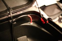
tx, There are other options or ways to make the top case more 'quick disconnect' friendly. The screw in connector that I used is heavy duty and works really well at keeping moisture out of the connection. However, Binder, the company that I sourced all of my connections from, has others that are 'snap-in' that have IP (or weather-tightness) ratings that are just as high. I just liked the idea of a mechanical, threaded means of cable attachment. And for me, it takes less than 5 seconds to unscrew the connector and the top case is free. I should also post an update sometime (your comment was a good reminder). The only issue that I have had is the way that I connected the wiring harness inside of the top case to the surface mounted connector. The way that the wires were connected, there was no strain relief for the soldered connections. Over the period of about 3 months, repeatedly dropping in and taking out my briefcase ended up loosening the soldered connections. The simple fix was to install a boot from an RCA connector that you can pick up at any Radio Shack. We'll see how it holds up. . . .I am thinking about beefing that up somehow too. Anyway, thanks for the compliment, and good luck if you take a stab at this!! Make sure that you post up pictures too!! -Nate
-
Thanks for the compliments guys. In my 14 years of riding, I have found that doing everything possible to increase our visibility to other vehicles is key to our survival!! (Plus, it looks cool and give me a continual source of projects to work on!!) And Jon28, sorry, but I'm not heading to Floridy anytime soon!! :laugh:
-
Essentially, yes. The LED's and the incandescent bulbs receive the signal at the same time, from the same source, but what you are seeing is that the LED's essentially come on immediately. Incandescent bulbs have to heat up the filament before reaching full brightness, which takes a few milliseconds -- long enough for the human eye to tell a difference beweeen the two. When I get around to changing out the rear combination lens to the clear from the '06 and later models, I intend to change to LED bulbs there as well (brakes and turn signals).
-
Videos can be found here: Vid 1 Vid 2 Vid 3 Enjoy!! :huh:
-
Ok. They are .avi files (windows). I'll get them up on here tonight, hopefully.
-
Ok, good idea about the vids. I took a couple videos, but how do I add them to the post? Can I host them on VFRD or do they need to have another home. . . .as soon as you guys help me figure out this part, they will get added to the topic!! :laugh:
-
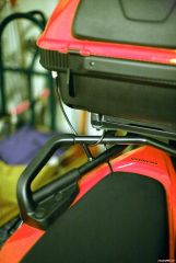
Joe - Yea, I had considered the GIVI connection technique, but determined that the manufacturing of the Honda OEM rack and top case were not really suited for that application. There is not a pre-formed 'knock-out' in the case or in the rack that allows for easy installation, unlike the GIVI cases and racks. Plus, for me, I rarely remove my top case. I guess if I do forget to disconnect the cable, I won't get too far!! I intentionally have the cable fairly tight for just that reason.
-
Thanks bayarearider. I have the headlight high-beam mod on my list too. I just need to pick up the relays . . . . I also want to change the front turn signals and the rear combination lens to the later model clear lenses. One project at a time I suppose!
-
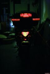
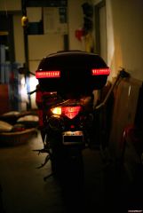
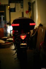
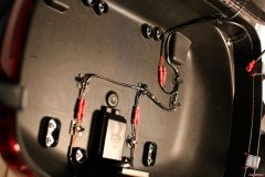
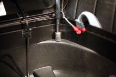
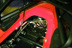
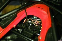
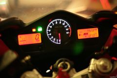
Alright. . . .here are some of the final pics, with the lights functioning at night. First, the running lights: 2008 VFR OEM Trunk Lights Part 3 001.jpg Left turn signal: 2008 VFR OEM Trunk Lights Part 3 003.jpg And brake light lit up: 2008 VFR OEM Trunk Lights Part 3 010.jpg I decided to disconnect the running light to the center LED since I wanted more of an impact when I hit the brakes - kind of the way that a center brake light works on a car. Hopefully, it will have the intended effect. Here's a shot of the controller wiring. The disconnected wire is the running light for the center LED: 2008 VFR OEM Trunk Lights Part 3 018.jpg And the controller nicely tucked away where it will live: 2008 VFR OEM Trunk Lights Part 3 017.jpg And a shot of the connecting wire from the bike to the OEM top case: 2008 VFR OEM Trunk Lights Part 3 020.jpg One of the other things that I did while the bike was apart was to replace the LED's in the gauge cluster. Red for the LCD's and white for the tach. I spent about 25 bucks on the LED's. It was a little scary taking the gauge cluster apart and soldering on the circuit board, but all turned out well!! 2008 VFR OEM Trunk Lights Part 3 016.jpg I know that I gave a bit of cost information in my first post. All told, this was not a cheap project, but I wanted to do it right, and I wanted something that would last. I estimate that I ended up spending about $200 total, but I think that the added visibility will be well worth the cost. Hope you guys enjoy!! I will also take a few more photos of the LED's in the daylight just to give you all an idea of how the case looks. Cheers!!!
-
LED Brake / Tail / Turn Signal installation in OEM trunk
-
-
From the album: Let there be (more) light!!
-
From the album: Let there be (more) light!!
-
From the album: Let there be (more) light!!