baraka
-
Posts
43 -
Joined
-
Last visited
-
Days Won
2
Content Type
Forums
Profiles
Gallery
Blogs
Downloads
Events
Everything posted by baraka
-
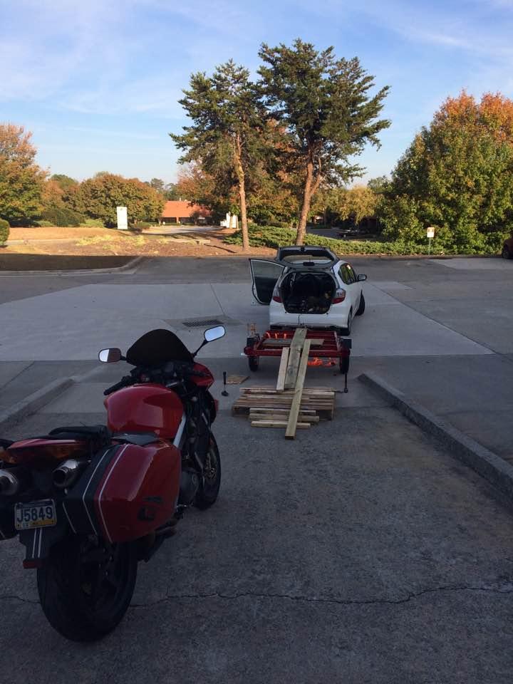
Hello fellow VFR Enthusiasts! Once upon a time, a long time ago, I was on a long meandering ride from Rochester NY to Philadelphia PA. It was unseasonably cold and my clutch fluid was probably low (yeah, I'm that guy who embarks on major road trips without checking all the vital fluids, I was young, and adventurous). Somewhere on the Delaware River I suddenly stopped getting response from my clutch. So I popped the old girl into neutral and coasted into a nearby NAPA. God smiles on fools. Over the course of the next four hours, I did my first clutch bleeding on the side of the road with my handy dandy underseat toolkit and a new bottle of brake fluid. I don't remember everything that happened, because it was a pretty wild four hours of improvisation, but I used a handy iPhone and this forum and a few others and nothing was working. Like most of the clutch maintenance/bleed threads, I was pumping and pumping the clutch handle and getting nowhere. Eventually I found a thread where someone had a little trick that I was desperate enough to try, and I tried it, and it worked. So naturally, now that I'm rebuilding my master cylinder, I went to find that thread and couldn't. But it worked beautifully, so I figured I'd post it here for two reasons: 1. Nobody should have to go through the misery of bleeding this damn thing and getting nowhere 2. Maybe it's a really bad idea and someone can explain why. In short, I rebuilt the master cylinder, bench tested it to make sure it built pressure, reattached it to the handlebar, banjo bolted it in, and pumped it until I was getting fluid at the slave cylinder bleed port. At this point, no matter how many times I pumped and bled, pumped and bled, I was developing no significant pressure. This is where the fun begins - I undid the three bolts that hold the slave cylinder into the motorcycle, and pumped until the slave cylinder was pushed out as far as it goes. At that point, I squished the slave cylinder piston back into the slave cylinder with my thumb, resulting in a huge, audible bubble of air coming out of the reservoir on the handlebar. I did this three or four times until the bubbles were much smaller. Pump the handle until the slave cylinder is all the way expanded, then manually push the cylinder back, resulting in burping and bubbling from the reservoir. Once I was only getting small amounts of bubbles out, I reinstalled the slave cylinder, and was able to get serious resistance at the clutch lever and actually build up enough pressure to successfully bleed at the bleed valve on the slave cylinder. I've done this twice now on my VFR, and I can't find any other source online documenting this technique, so I figured I would share it here for wiser heads to determine if it's a good technique, if there's any way this could damage by slave or master cylinders, or maybe help some poor schmuck stuck on the side of the road out. I was working under pretty primitive conditions last night so I don't have any pictures, unfortunately. Instead, here's a picture of my last really bad idea so you can comprehend the general level of redneckery I'm comfortable with during maintenance procedures: Cheers!

-
Absolutely! Itinerary so far is: Day One: Thousand Islands Parkway from Toronto to Montreal Day Two: Follow the Saint Laurent as far north out of Montreal as we can in a day...hopefully deep into coastal New Brunswick. Need to find some camping up around Matine/Lac Matapedia/Saint-Anne-De-Monts Day Three: Cut across to Dalhousie and follow the coast down into Moncton for a weekend of wedding festivities and day trips around Prince Edward Island and Nova Scotia! Regression: as far down US-1 through Maine and New England as I can get before running out of vacation time and gas money! Then back to Pennsylvania!
-
It's been years since I've had a chance to visit Canada! I'll be in the Toronto area in June for the Horizon's Unlimited Meetup, and then heading out to New Brunswick for a wedding. Very excited to see parts of Canada I've only dreamed about! My loose plan is to take three days to head east from Toronto to Moncton, spend the weekend in and around Moncton and hopefully check out Nova Scotia, and then head back to Pennsylvania through the states. I'll be traveling light and camping, hopefully avoiding boring slabbing on highways and seeing beautiful scenic country and nice twisty roads. I've never been in those parts before: if anyone has any recommendations on good roads to ride, places to camp, sights to see, and amazing food to eat, that would be awesome! Dan
-
Strip off the soaked clothes, sit next to a fire, drink an adult beverage and feel superior to all those fair weather birds who melt in the rain?
-
She hasn't gotten back to me with pictures. Email only so I'm waiting on a reply.
-
Excellent points! I am mainly tempted by being able to pick this up for a song. Didn't know about the tires/chains, and recent experience teaching a friend how to ride has made me re-evaluate the "buy an old bike that you don't mind dropping" notion. Maybe it would be better to "buy a bike with decent suspension and brakes that feels more controllable for a beginner." I love the Ninjas and Honda 250's, but this looked like an interesting, and much cheaper, option. I have to say I have been dying for an excuse to buy a CBR250R. They are dead sexy. I need to take one out for a test drive. I really really want a Repsol replica one, but I can't justify the cash for it right now. Especially if a new rider's going to be on top of it :)
-
I was hunting Craigslist and I found a VFR250 from 1988. The seller is asking US$900 (I'll, of course, offer less) and says it needs the alternator to be replaced, but says it runs. Any thoughts? I'm interested in picking of a bike for a 5'04 female friend to learn to ride on. Good idea, or bad idea? http://atlanta.craigslist.org/atl/mcy/4099542839.html
-
 Love those wheels!
 -
 Beautiful!
 -
Well. Update for the troops: I am back on the road after fixing three things: 1. New grounding line to the front wiring harness, to fix the poor ground in the ignition circuit. 2. New power line run to front high beams, and extraneous loop cut out of front wiring harness. 3. New ignition pulse (or crankshaft position sensor) and bolt. The old one's mounting bolts had vibrated out and were chilling out in the oil pan. :( But, :), they were not chewed up. Much thanks to all who helped trouble shoot, and PoniesAteMyBagel and Tightwad for timely help with parts.
-
What he said.
-
-
Well, I was homeschooled in a family of electrical engineers, so dinner table conversations often involved actual usage of voltmeters...I definitely called up dad a few times during this little project. He spends his spare time fixing household appliances and stubbornly refusing to let anybody else fix his cars. Good resource to have, because this stuff gives me headaches.
-
Well here is the crazy thing. I snipped it all out except for the small red and white wire, which I snipped where it joined in with the other red/whites. I wired a new, 8 gauge ground wire from the frame to the front wiring harness and commoned it with all the grounds. It's a good thing I saved most of that little red/white wire, because that is the power feed for the high beams. It runs to a small 20A feed, and from there to a black/red or black/yellow wire to the high beam relay. I have no idea how the high beams were powered before I took this whole thing apart, as I cannot find any other wiring that was wired into that loop. I can only chalk it up to witchcraft. The recall is on the books as having been done. But the wiring harness is kind of bizarre, and the vfrness doesn't fit the R/R connector. The three yellow wires are connected using a three pin connector. I looked at the recall wiring schematic, and it has a red/white tied into the main red/white in between the 20A master fuse and the regulator/rectifier. So I found a convenient spot on the wiring harness side of the regulator/rectifier plug and button hooked the red/white power feed to the high beams into one of the large gauge red/white wires and crossed my fingers and called it a day, under the theory that both red/whites attached to the R/R are commoned on the schematic, and I am mimicking the recall wiring harness schematic, and there is a twenty amp fuse on both sides of the connection. Nothing has lit itself on fire yet... My only concern is that I am somehow altering the delicate RR/Stator balance and will begin over/undercharging the battery. I will run some voltmeter tests shortly. The other problem I have is, the connector with three yellow wires looks to be an aftermarket three pin, and won't mate up properly with the VFRNess, so I haven't decided how to proceed there.
-
-
-
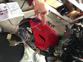
From the album: Mechanic Time
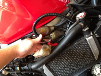
Bubba rigging on top of bubba rigging. I tied the power feed to the high beams into the the wiring harness side of the red/white power line tied into the regulator/rectifier. I hope this is not a bad idea... -
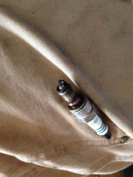
Well. As the doctor would say, there's good news and there's bad news. The good news is, I have found problem #2. A giant point of confusion here has been that the ignition pulse generator has passed all the external tests, but all symptoms point to it not doing its job. So I pulled the right crankcase cover of and, lo and behold, a bolt drops out into the oil pan...hmmmm... Sure enough, further inspection reveals that the ignition pulse sensor is simply hanging by its wires. I have found my problem! Apparently the bolts holding it in place vibrated out and it fell out of place. It looks a little the worse for wear: the magnetic "nub" is reduced a little bit, probably from contact with the timing sprocket. The sprocket looks pretty good, and I have a replacement sensor and a new gasket for the crankcase cover. I simply drain the oil from the oil pan, recover the sensor mountain bolts, and I should be back in business. Except there is only one bolt in the oil pan...and I distinctly remember only one bolt falling out when I took the cover off. There are supposed to be two bolts. Either a) the PO only mounted the sensor with one bolt, or b) there is a bolt sitting in my oil pan. Did I mention that one of my favorite mechanic games is "Find the Bolt?" Welp. I'm going to try the whole "magnet on a stick" trick before I go and pull the oil pan. Maybe I'll get lucky...at least it looks like I have found a solid reason for the original problem. Once I get this figured out, I'm gonna locktite those two bolts in.
-
Dales--I sure hope not. I have to take the righthand crankcase cover thingy off to replace the ignition pulse sensor, so I'll check timing while I'm down there. But my main problem is that I don't have any spark to the plugs at all. So I'm not terribly concerned with the timing. I did preliminary checks on the stator, and it has proper resistance between the coils, and does not have any shorts to ground. But I haven't laid eyes on it yet. Could a problem with the stator or the rectifier cause a no spark issue? People are suggesting that I'm being foolish in attempting to troubleshoot an ignition problem without addressing the stator/RR issues, but the RR is an updated one, and the stator passes the initial voltmeter test (resistance between coils, no shorts to ground).
-
Well. I ran a new 10ga ground from the front wiring harness straight to the grounding point by the fuel tank hinge. Voltmeter says it's a huge success, and the ignition relay circuit lit up quite nicely. I now have initial power to the spark plugs, a nice whirring fuel pump, and...still no spark at the plugs. I can smell gas when I turn the engine over, but I can't get any ignition when I hold a lit lighter up to the open spark plug hole. I've checked ground from the ECU (both green/pink wires and the green wire), and it's good (0.1-0.5 ohms). I checked continuity on the wires from ignition pulse and cam pulse generators, and they are good. I even grounded out a coil and plug and ran 12v to both leads and got good sparks, so it's not a coil or spark plug problem. At Kaldek's suggestion, I unplugged the ignition pulse generator and turned it over for a bit, and it threw the FI light for the ignition pulse generator. Did the same thing for the cam pulse generator, and it threw the code for the cam pulse generator. In theory, this means that both are working, because signal from one but not the other is how it indicates that the other is not working. The only thing left in the system, as far as I can tell, is the ECU. I picked up a used ECU from an '02 ABS from Poniesatmybagel, and plugged it in today, and nothing changed. The ECU's appear identical, but his is labelled "38770-MCW-L02-9697-100420" and mine is labelled "38770-MCW-L02-9697-101205". That's the only significant difference, and I have no idea if it's important or not. They are both made by Keihin. I guess the next step is either shell out the big money for a new ECU, or find a kind soul with a running bike to swap ECU's with for a test. If anybody in the Atlanta area would like the help, I would be in their debt. I just found out that I have a funeral to attend in Michigan next weekend, and I don't have any running mode of transportation, so I'm getting sort of desperate for answers.
-
Kaldek, If these things are all controlled by the ECU controlling the ground, did I just FUBAR everything by wiring an independent ground into the ignition loop?
-
Well. To be honest, I'm not really sure. Around the thirteenth or fourteenth hour of fault hunting in a dark garage by yourself, you enter a sort of Heart of Darkness like experience of increasing bizarreness and desperation. The thoughts you are thinking seem to be intelligent and rational, but after sleep and re-exposure to other people... I decided to check the ignition circuit since I had no spark. As I took the bike's front fairing apart, the problems got worse: no spark, then no fuel injection, then finally no fuel pump as well. I decided to check the engine cutoff relay. It was not relaying. Sweet! But before I shell out some money to buy a new relay, I tested the relay by connecting it straight to the battery as described in the manual, and voila...it worked fine. Crap. I decided to check the voltage in the circuit from the top down. Started at the bank angle sensor, then the engine cutoff, then the fuel cutoff, then the kill switch...and they were all showing 12.5-12.3 volts. I was confused. How could there be 12.5-12.3 volts at every connection in the system, but the relay not work? Well, if I had paid attention when I was a child, I would have known the answer. To explain, there are two types of people in my family: electrical engineers (My dad, and my brother) and liberal arts majors (my mom, my other brother...and me.) So I bit the bullet and called Dad, and explained my process, and he laughed and pointed out that I was testing voltage from each point on the system to the ground lead of the battery, so I had verified that power was available all the way through the circuit, but the circuit was not complete because I hadn't checked the grounding of that circuit--by grounding to the battery terminal for ease of testing, I was bypassing the circuit's ground. Then he said something about how if I had paid attention during the eighty billion times he dragged out the voltmeter to work on the car or washing machine or furnace, then perhaps I would not have these problems, and maybe I should have studied something more useful in college than Political Science. Actually, he was really nice about it. So I went down and measured voltage across the leads of each relay and the bank angle sensor, and none of them had any voltage. So I ran a tester lead from the battery ground and touched it to the ground lead of the bank angle sensor, because that was the only ground lead I could find in the wiring diagram for the ignition circuit and WHAMMO! Lights came on in the instrument panel, the fuel pump whirred to life, the relays all clicked and I started singing the hallelujah chorus. I checked the voltage to the ignition coil, and it was there, so this should solve the spark problem (unless all four coils went bad simultaneously). I tore apart the wiring harness and this is what I found: Previous Owner, my God have mercy on his soul, apparently decided to rewire the R/R into what I can assume is a dedicated circuit. My best guess is that the ignition circuit was grounded and powered through the R/R ground. PO (mGhmohs) then installed a new R/R and a new wiring harness, but didn't know what to do with the old harness...so he cut the wires off the R/R and looped them to each other and electrical taped the whole thing up and said f*** it, let's ride. Oddly enough, the quality of the work is high: copper crimping, no corrosion whatsoever, purple patch tape over the crimp spots, electrical tape and heat shielding over it all, and routed carefully, with OxGuard on the connectors. So here is 12 or 10 gauge ground wire, run in a loop to itself, with a connector in the middle of that loop, and it goes to nowhere. They are tied independently into the small green ground wires from the ignition circuit and headlight circuits. Also, there is another deviation from the wiring schematic: there is supposed to be a small green ground wire going through the gray 16 pin connector from the ignition circuit back to common ground on the bike, but it is not there. There are only 15 wires in that connector, when there are supposed to be 16. So there is no direct path to ground for this circuit. Instead, the whole headlight, high beam, and ignition circuits are currently going to ground through a green/black wire that grounds out the instrument cluster. All that green ground wiring in the picture is joined into one itty bitty green wire through that yellow junction block. That one ground wire goes into the instrument panel, where it encounters 110 ohms of resistance before connecting to the instrument panel ground wire, which proceeds with 0.4 ohms of resistance through the 16 pin connector and on to the chassis ground. My best guess is that there was a connection in the instrument panel between the ignition circuit ground, and the instrument panel ground, and when the PO realized that the ground was working after rewiring the R/R, he said, "F*** it, let's ride!" and our inadequate little Horatius on the bridge heroically held out for eight or nine thousand miles and now is so fried that he can't hold on any longer. The connection is there...you can get from any point in the ignition circuit to the ground, but you have to go through 110 ohms of resistance to get there. Dad did a little very rough guesstimation over the phone and decided that we are looking at something in the realm of 100 amps to make that circuit work against that resistance. All the wires in the ground are internally continuous--no resistance. The only resistance is between the leads on the instrument cluster where the green wire goes in, and the green/black wire comes out. The red/white wires are tied to themselves, with a smaller red/white tied in, which leads to a fuse, which leads to a green/yellow wire that goes to one of the headlight relays and doesn't appear to carry any current. I have no idea what it is for. There's also a white/black wire tied into one of the red/white ones, which goes to the connector, but there is nothing on the other side of that connector for it to connect to. It's a very lonely connector. Since I can see no point in any of the large green/red and white wires in that loop, I'm going to chop them off, wire in a nice phat 10 gauge ground line to all those little green wires, and run that independently back to the chassis ground underneath the seat. Then we'll see if she fires up. I'll probably test the R/R and stator while I'm in there as well. Just to be sure. VFRness is due to come in the mail today, so I'll stick that in while I've got the whole thing torn apart. Hopefully the custom harness job isn't so hacked that the VFRness won't install...
-
Guess what? Bad ground from the bank angle sensor due to the rewiring from the previous owner...
-
Okay, fess up, who did this? I am in the process of tearing apart the front wiring harness of my '02 VTEC/ABS, because my ignition circuit (with the engine relay and fuel cutoff switch) was working poorly, and I discovered this. If you can explain the thought process behind this, I will buy you a box of Girl Scout Cookies. The entire front end of the wiring harness is grounding through one 14g green and black ground wire coming out of the instrument cluster which has, predictably, given up the ghost and is reading 110 ohms of resistance to the ground. I think the connector is the connector for the regulator/rectifier. But it's clearly no longer on the R/R. The green loops connect to themselves to form independent loops. The Red/White wires are connected to each other to form one long loop, also connected to themselves, forming separate loops, with a little red/white wire tied in to one, and a white/black wire tied in that leads to the connector, but doesn't actually connect to anything. The little red/white wire is connected via an independent 20A fuse by the right side access panel to a black/yellow wire, which leads to one of the headlight relays, but I can't get any power to flow for it. The real question is, is it a loop to nowhere, and can I cut it out? Especially the green.
-
From the album: Mechanic Time
-
Copy that. The fuel pump does whirr for five seconds as normal whenever the ignition is activated. That's what confuses me about the lack of fuel to the cylinder. When the bank angle relay or the engine cutoff relay drop, would that cut power to the fuel pump? Should the presence of the fuel pump working, but the injectors not injecting, indicate a faulty ECU, or could that be a result of: a) bank angle sensor failure/misconnection b) engine cutoff relay failure/misconnection c) kill switch fault d) something else I'm not thinking of. My process of thinking is, if the fuel pump is working, and the fuel regulator is working (it isn't leaking when I pull the vacuum hose), but there's no spark and fuel in the cylinder, then whatever sends the signal to the fuel injectors and to the coils is faulty: either the cam pulse generator, the ignition pulse generator, or the ECU. The reason I'm not looking at the sidestand switch or the kill switch primarily is because the engine will turn over right now. Could it be possible/probably that a fault in these switches will allow the engine to turn over without spark or fuel injection, but with the fuel pump working?