

Mohawk
-
Posts
1,991 -
Joined
-
Last visited
-
Days Won
47
Content Type
Forums
Profiles
Gallery
Blogs
Downloads
Events
Posts posted by Mohawk
-
-
You should try the engine braking on an Aprilia RSV4 - its like throwing a frigging anchor out and deploying a drag chute
 Mind you I actually like engine braking
As you have both, how does the engine braking compare to your 6th gen ?
-
You can save a few $/£'s by using a dual vacuum gauge. I do, just connect one to whichever is the non adjustable one on the 6th gen, get the bike to running temperature, then check the measurement, now attach the other gauge to the same source & compare the reading to give you a +/- factor. Return the 1st gauge to the static source, then add the 2nd gauge to each of the other ports & adjust. Remember that everytiem you make an adjustment, check & correct the idle, then recheck all the other ports.
I find on my 5th gen when you hit the sweet spot, when you rev the engine, you will hear & feel the smoothness & the engine revs up much quicker & smoother. Feels much nicer to ride once setup correctly. Loses much of the snatch in the throttle & is smoother everywhere.
One other thing to check, is to set the throttle free play to ZERO, be careful when adjusting it, swing the bars through there full range, you may need just a smidge of free play, this makes adjusting the throttle at small openings much smoother.
-
It's a great idea, but to achieve it you would need fly by wire throttle bodies. The main issue is that you want less engine braking, whilst decelerating & keeping, the throttle butterflies open with zero fuel supply will achieve this as you expect. With the TPS at zero & the engine turning, zero fuel is supplied, which is WHY the 5/6th gens have such a strong engine braking feeling. With carbs fuel is always added, so less apparent engine braking.
Now if you adjust the butterflies to be slightly open when TPS is at zero, the bike will stall when you stop, due to to much air & not enough fuel. It will also be impossible to balance the throttle bodies vacuum due to there being NO way to adjust the butterflies separately like you can on a carbed bike !
What you really want is a stepper motor with controller between your throttle cables & the throttle body butterfly actuator, i.e. take the cables OFF the throttle bodies & connect a stepper motor there. Then program the stepper to keep the throttle slightly open when bike speed is above say 10mph, but close fully when throttle is closed below that speed, thus preserving the idle & vacuum balance required at a stop. This would require an electronic throttle & some nifty programming & wire harness interface.
Alternately you can ditch the EFi & fit carbs, a much simpler solution potentially, but full of it's own pit falls !
Have fun.
-
Hey Larry, as always excellent work. Love it. I didn't see your CMC front upgrade before, is there a thread for it ?
How long did the mods to the disc take you ? That is some serious machining. I've never seen the CMC material in the flesh, is it more like a metal or a ceramic ?
Keep up the good work.
-
Yes replace ! :)
-
Car type folding mirrors & some older bikes, use a thin stiff flat spring with detents for mirror arm location. You could modify the VFR arm & hanger to achieve this, then use a a kickstart fold out foot piece spring, i.e. those with the top arm that folds out rather than those that pivot at the bottom. Maybe a heavy duty spring washer would be enough.
If there is enough room, then you could use pins through the hanger to stop the stalk folding back, so would need to run the tension bolt a little loose & then use a U shaped pin, so it locked out front & rear folding. If yo were really good, you could make a lock like a gun magazine release to lock & release them !
Lots of ideas, or as previously said, just make a new gate !
-
Basically the rear braking system is the same for both gens. The fronts are slightly different. So if it just moving the lines into the swingarm, then its fine.
I had to totally delink mine to fit the single nut rear wheel, but I put the remaining brake line through the swingarm, as per the pics below.
The line runs forward from the rear master cylinder, inside of the foot rest hanger, then under the front of the swingarm & enters in to the arm via the square hole that is already there on the left inner side. It exits through the drain hole at the rear, which I rifled/drilled at an angle to make it big enough for the banjo head to fit through & gave the right angle for the hose to exit towards the new caliper !


Have fun.
-
I've been thinking about this & as the RC51 rads are hard to come by in the UK. Another option would be a second 5th gen rad (which are cheap) welded to the existing one or 2 x 5th gen rads made up to replace the existing one which could be resold.
The process is simple, take one rad & cut off the oil pipe mounts, then take the 2nd rad & cut/grind off the frame mounting tab on the top. Drill an 8mm hole in the top at each end inline with where it will align with the holes in the bottom of the first rad & then rim weld them together. Job done, a 4 row cooler.
I'd be inclined to replace the pipe mounts with oil cooler hose mounts & have a set made up to replace the oil cooler pipes which are known to corrode & leak on the 5th & 6th gen if not looked after ! This will be my first project next winter

-
Sorry to hear that your ebg has let you down that badly. I'm an ex mechanic & I hate giving anything to anyone to do stuff for me but sometimes it's the only option & sometimes my worst fears are realised as in your experience. I can imagine how you feel, I'd be gutted beyond belief.
I hope you find a solution soon. Good luck.
-
-
-
Nice work, check out my 5th Gen Upgrades in this thread
-
OK, did an amp check on a spare battery. CBR CoP units draw 7.5amp. Original coils draw 3.9amp. These are COLD figures, the CoP units resistance goes up with Temperature. Your choice, works fine for me ;)
-
Well I remembered to test the coils resistance last night, the CBR1000 (2007 model) CoP units register 1.5ohm, the original VFR coils show 3ohm.
A previous HOT resistance check on the CBR CoP showed 2.5ohm, so I'm happy. I'll try to do an AMP test tomorrow, won't have time today.
-
So would you suggest all modern gsxr coils are the same?
I think the GSXR 600/750 & poss 1000's are all the same, as the engines are practically the same. I used CBR ones, beacuse they were available cheap at the time I was looking. GSXR ones would probably be better as they are a little shorter. I had to add a couple of O-rings to my CBR ones to centralise them in the hole & seal it against water/dirt entry !
Strange I was a Bristol Flyer courier in 87/88 then had an acciden that put me out :( Best job I ever had, people think I'm nuts but nothing I've done since was that enjoyable !
-
The plugs have no bearing on the use of CoP, but you asked which plugs I use !

-
I use NGK iridium plugs on all my bikes, never change them, I've never had a set wear out :) Just clean & check them when I do valve adjsutments.
-
I think you guys are reading too much into this. Coils are really simple, they don't draw hardly any ampage, just look at the length & diameter of the cables from the ECU which only acts as a trigger unit to collapse the Low tension field to generate the HT field. Coils DON'T use much juice. The resistance of a coil is directly related to the amount of power it requires, the newer ECU's are even smaller than the old tech VFR one & they use the same grade wiring for their CoP units. In theory a 3ohm resistance should draw 4amp & 1.5ohm 8amp, but when i tested the original coil it only used 2amps. I'll test one of each on Monday evening to see what they register.
-
Pic of working rear ones & test fit of front


-
About a thousand miles with the 2 rear cylinders running the CoP.
-
Oh and another thing re the CoP issue. I tested the ones I've used & if memory serves the resistance was about 3ohm of the orginals & only 1.5 on the CoP, so I ran the rear two, then had a brain wave, that resistance increases with Temperature, so got everything ready to test the rear CoP with the bike hot, remember that CoP sits in the plug tunnel surrounded by HOT metal. It took about 2-3 minutes to stop bike get off, get meter & attach whilst trying not to burn myself & the resistance hot was 2.5 so close enough in my opinion & has been running great since !
-
 1
1
-
-
VFR750 crank:
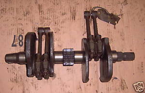 If we put a piston on each conrod, and then put those pistons into their respective bores, I believe we would have two pistons at TDC and two pistons at BDC, the angle of the V would have no bearing on this whatsoever. RC45 crank, for reference:
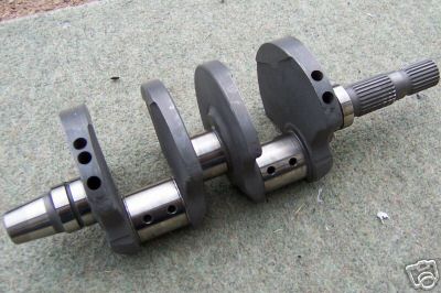
he he he, are you forgetting that in a V engine the conrod big ends share a crank pin & thus when one is at TDC, the other can't be. On a VFR cyclinder #1 is the rear left & it shares a crank pin with Cyl#2, which is spaced 90degrees futher on,so can't possibly be at TDC at the same time. Plus remember that each piston requires 720degree between firings.
The best you could do with a V4/180 crank engine is this, 1-2-3-4 all 90degrees apart, then have a 450degree freewheel cycle or a very rough running engine, or need a VERY big flywheel to carry it over that hump !
You could twin up a 360 crank, with 1+3 then 2+4 90 degrees later, followed by a 450 degree freewheel cycle, again a very rough engine with huge pulse power delivery, which would in theory require larger bearings & shafts to deal with the extra grunt. OK in a race engine maybe, but not a road bike, if you want to keep your teeth :)
The screamer engine or as close as you can get with a V4 works by using some of the power stroke of one piston to power the compression stroke of another, this allows the crank webs (flywheel). The V4/360 big bang would have to rely on flywheel momentum to force two full & two half comp cylinders to TDC on compression with the second two only 90degrees behind the first, that would require a lot of weight in the flywheel to carry that through TDC's for both banks.
-
I've added CBR1000RR CoPs to my 5th Gen, 2-wire units, 2007 model I think, needs an O-ring to seal the plug tunnel & keep the the CoP from flapping about, but I ran the rear 2 for 3 months on CoP & the front on standard coils as a test, works fine. Will be adding the front 2 CoPs during my rebuild at the moment.
-
Oh forgot one thing, your EBD may be wrong about the oil cooler ! If as he asserts the oil flow is not great then an upside down cooler would crud up with contaminated oil, as the cooler is a sperate circuit to the pressure feed system & pumps oil straight from the sump to the cooler. By being this way up there is no dead space for old oil crud to collect. I think you will find there is easily enough flow to use all the galleries in the cooler.
If you look at my second ramair solution, this increases flow to the cooler & I will add a baffle underneath between the cooler & the cylinder head cover when I put it back together, this will further increase airflow through the cooler due to the baffle causing higher air pressure in front of the cooler & lower air pressure behind it at the same time !


Can We Reduce Engine Braking?
in Modifications
Posted
Here's a test for you then, which will prove the point that its the throttle being closed causing the issue. Find an empty bit of road, accelerate to which ever speed you choose in whatever gear you choose then close throttle & measure the roll down distance to a low speed or stop. Now repeat the exercise exactly as the first trial, but instead of closing the throttle, just hit the kill switch & leave the throttle open ! You will find the retardation is much reduced & you should roll a lot further.