Dutchgixxer
-
Posts
111 -
Joined
-
Last visited
Content Type
Forums
Profiles
Gallery
Blogs
Downloads
Events
Everything posted by Dutchgixxer
-

How to remove power limitations 1st and 2nd gear
Dutchgixxer replied to Dutchgixxer's topic in Seventh Generation VFR's
Got this from another site. The author is a Honda Mechanic. "the thing is like this... you wont derestrict it as it is not restricted in anyway. The clutches are programed to ingage softly at a rate that the gear change is hapening much quicker than any person can do on a regular gearbox. Meaning that if the 1st and 2nd were restricted the clutch engage rate should be diferent for those two gears...but it isnt ;) . All together it is a complicated system that you dont want to mess with with any resistor plugs or symilar... Trust me when i say...leave it alone. So lets get to the speed limitation... again it is in the ECU and it is there because bikes cyclistics are not up to the higher speeds than the 250 km/h she is doing now (and Honda dont wants that somebody gets killed at that speed as the bike could be unstable ower 250 km/h). Alltogether it is a triple secured system and it is impossible to change it without interfering in the ECU (only Honda can do that in the factory, but they wont) and fooling around with some blind plugs or resistor plugs for the wire loom conections will throw a fault light on your dashboard and you will be able to engage the 1st or 2nd gear only (sort of a limp mode to help you get to the nearest Honda service if something goes bad on the trip). And then you wil need help of course (to get that gearbox back in neutral and get you going again). Bottom line...dont touch anything on the bike...do not disconect any sensors, cable conectors or unknown switches as it will triger the fault light and it will record the faults in the ECU unit." I think its safe to say that this applies only to the DCT bike. Means my dream is up in smoke! :angry: For the DCT the only mod possible is the speed derestriction mod. I you tell the ecu that the speed is 250 km/h while riding faster there is no error generated. For the manual clutch type all the mods are easy with no errors generated. No restistors are needed. I am no Honda technichan but an electrical engineer. -
How to remove power limitations 1st and 2nd gear
Dutchgixxer replied to Dutchgixxer's topic in Seventh Generation VFR's
:laughing6-hehe: -
How to remove power limitations 1st and 2nd gear
Dutchgixxer replied to Dutchgixxer's topic in Seventh Generation VFR's
Hi VFRRider, I am also interseted in a true plug and play connector. Maybe it is possible to get one through the Honda dealer (without cable harness). Ralf. Honda is not going to help you! Honda has decided to restrict. They will not help to derestrict -
How to remove power limitations 1st and 2nd gear
Dutchgixxer replied to Dutchgixxer's topic in Seventh Generation VFR's
So, with the snip method, does the gear indicator say 3 in 1st 2nd and 3rd gear? Yes you are right. The ecm is fooled to derestricd 1 st and 2nd gear. The ECU thinks the 3 rd gear is used while it gearbox is in 1st or 2nd. It works perfectly and its a simple mod. 1st gear = 3rd neutral = neutral 2nd = 3rd 3rd = 3rd 4 th = 4th 5th = 5th 6th = 6th If you do not like wheelies you can decide to leave the 1st gear as it is. :biggrin: -
How to remove power limitations 1st and 2nd gear
Dutchgixxer replied to Dutchgixxer's topic in Seventh Generation VFR's
Please check post #46. I need a male and a female connector. -
How to remove power limitations 1st and 2nd gear
Dutchgixxer replied to Dutchgixxer's topic in Seventh Generation VFR's
I have just been out on the 1200. Made the first 70 km on the VFR in 2011. Roads where dry so i could play a little with the bike. The derestriction works fabulous. The hessitation in 1st and 2 nd gear below 5000 rpm is completely gone. The sudden torque increase if the revs rise is not feelable any more. Its a better mod than putting a Akra on the VFR. Costs of this mod $7. Espesially fore mountain roads riding ( i use the low rev range a lot comming out of tight bends) this mod is very adviseable. I have also experienced the quality of the öhlins rear shock. What a difference. Its more comftable but better damped. I have to tune it futher. But i need warm tarmac for that :cool: -
How to remove power limitations 1st and 2nd gear
Dutchgixxer replied to Dutchgixxer's topic in Seventh Generation VFR's
Supply me the right connectors. I will make you a wireing harness. -
How to remove power limitations 1st and 2nd gear
Dutchgixxer replied to Dutchgixxer's topic in Seventh Generation VFR's
Mine is ready and working. It is not PnP but is works. its switchable so for me it is not a problem that the gear indicator gives false reading in 1 st and 2nd gear. The bike wheelies off the throttle in 1st :) -
How to remove power limitations 1st and 2nd gear
Dutchgixxer replied to Dutchgixxer's topic in Seventh Generation VFR's
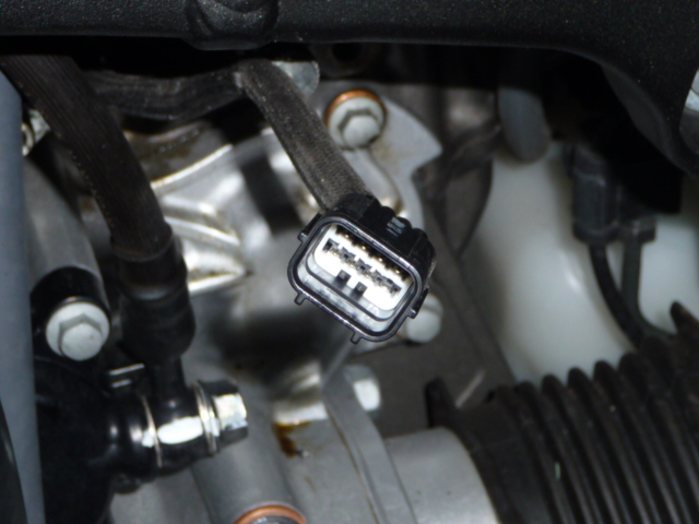
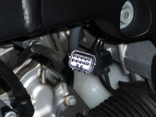
Who can provide me 2 pair of Gear Position Sensor plugs. 2 male and 2 female plugs. I Will send you a wiring harness back with switch-able 1st and 2nd gear de restriction abillity . It is a 8 pole connector with 7 poles used.
-
How to remove power limitations 1st and 2nd gear
Dutchgixxer replied to Dutchgixxer's topic in Seventh Generation VFR's
Yep and if you could build a bunch of them cheap I bet you could sell them for 50 bucks a shot. Can you figure out wich molex connector it is ( Gear position sensor harnas near the switch ) ? Thank is advance ! -
How to remove power limitations 1st and 2nd gear
Dutchgixxer replied to Dutchgixxer's topic in Seventh Generation VFR's
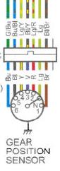
The trottle valve is operated by a closed loop servo system. The ECU reads the trottle valve position it is compared with its desired position. If there is a diffence ( error ) a correcting action is taken. The 4 wires are the 2 motor wires and 2 wires to measure the current trottle valve position. If one of the wires is cut or moddified the trottle by wire is not working any more. So do not mess with the closed loop servo. Btw i am busy decoding the "serial link" to the combined dash indicator. to be continued. :cool: -
How to remove power limitations 1st and 2nd gear
Dutchgixxer replied to Dutchgixxer's topic in Seventh Generation VFR's
Well i also say bullshit Why ?? in 1st and 2nd gear the bike is restricted. But till 5000 rpm. After 5000 rpm the power builds till a 150 hp on the back wheel. If the gearbox could not cope with the power Honda should have made a restriction on top power not just at low revs because the power is there already lower. The low rpm restriction in 1st and 2nd gear is just simple and cheap traction control. -
How to remove power limitations 1st and 2nd gear
Dutchgixxer replied to Dutchgixxer's topic in Seventh Generation VFR's
The wires coming from the GPS need to be in the middle of the switch, and either set of leads coming off either end. Then in one ON position the sensor is hooked to the ecm, on the other ON position, you GPS is hooked to your modded wiring where it sends the GPS signal right to the 3rd gear wire. Jason :fing02: -
How to remove power limitations 1st and 2nd gear
Dutchgixxer replied to Dutchgixxer's topic in Seventh Generation VFR's
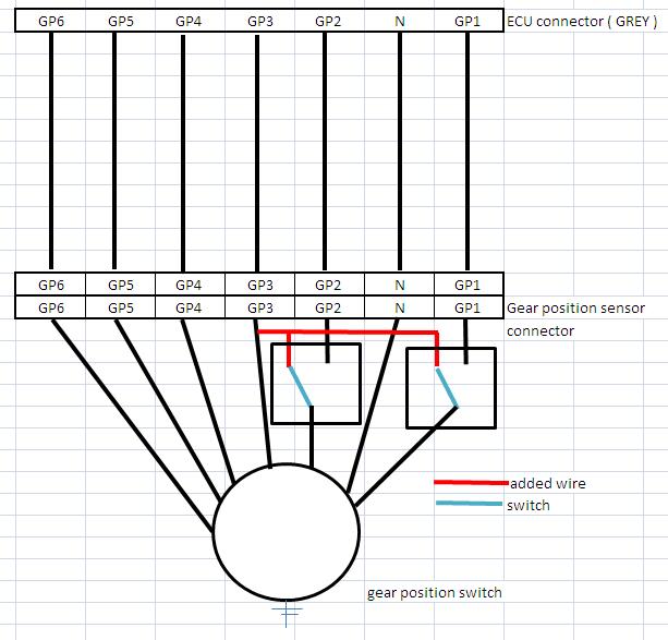
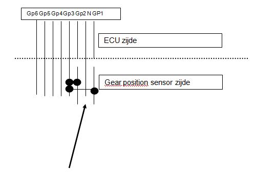
I think your wiring diagram is false. In the derestriced mode 1st and 2 nd are always connected to the ECU. The ECU sees 2 gears engaged. The GPS for 1st and 2nd wires have to move to both the middle ( P contact ) poles. -
How to remove power limitations 1st and 2nd gear
Dutchgixxer replied to Dutchgixxer's topic in Seventh Generation VFR's
Double-Pole-Double-Throw On-On switch. Like this one: http://www.thesource.ca/estore/Product.aspx?language=en-CA&catalog=Online&category=Switches+Switches&product=2750636 It is an "on-on" switch with 6 terminals. I think I might repair my harness wiring then install one of these under the seat tied into the wiring near the GPS for switchable power modes. Thanks for the explanation. I prefer 2 single On-On switches. -
How to remove power limitations 1st and 2nd gear
Dutchgixxer replied to Dutchgixxer's topic in Seventh Generation VFR's
Now you have individual switches for 1st and second gear... Good idea I might do the same. It's probably advisable not to flip the switches when the bike is in first or second. Otherwise you could throw a fault code. edit: a DPDT switch would also work. Please explain what a DPDT switch is. Thanks -
How to remove power limitations 1st and 2nd gear
Dutchgixxer replied to Dutchgixxer's topic in Seventh Generation VFR's
I think you hit the nail on its head. :biggrin: I have chanced the scematic a bit. I have made de de restriction switchable. Some testing learned that when using sports tires ( i do ) in cold weather or in the wet its very easy to spin the rear wheel. Phobe had alterted the wiring near the ecu. I have made the mod near the GPSensors connector. Its just a choise
-
How to remove power limitations 1st and 2nd gear
Dutchgixxer replied to Dutchgixxer's topic in Seventh Generation VFR's
I think you hit the nail on its head. :biggrin: -
How to remove power limitations 1st and 2nd gear
Dutchgixxer replied to Dutchgixxer's topic in Seventh Generation VFR's
While this looks feasible in some respects, I would caution that unless you know what the I/O interface properties are, you may be violating circuit constraints which would then risk a blown sensor or worse. I offer the following scenarios: 1. Each output of the GPS is an open drain that is asserted Low (or simply grounded) for a given gear selection. Then tying 3 output wires together into one input as you have shown is a wired OR gate and will logically work. 2. Each output of the GPS is an open drain that is asserted High (or simply opened) for a given gear selection. Then tying 3 output wires together into one input as you have shown is a wired AND gate and will NOT work as all 3 outputs must be asserted High simultaneously which will never happen. 3. Each output of the GPS is a CMOS type output that is asserted High (i.e. actively driven high) for a given gear selection. Then tying 3 output wires together into one input as you have shown is a definite circuit rules violation as the output that is attempted to be driven high will be actively countered by the other two outputs which are actively driven Low, thus causing a near direct short to the supply voltage and maybe a fried GPS. Perhaps you've already found that it does work as shown, in which case scenario #1 is most likely true. If it doesn't work, then beware of scenario #3 which could end up costing you some $$$ to fix. Good luck in your efforts, I wish I could do the same but the DCT control needs to know the actual gear selection otherwise it would be constantly trying to downshift below third and never finding it. Thanks for your reply. I found from the honda scematic that if a gear is selected the ECU input is pulled to ground. ( your option 1 ) The screenshot with the color in it is a screenshot from the OEM honda scematic. This mod is not working for a DCT. I have added 2 scans of the OEM scematic. schema L.pdf schema R.pdf -
I have derestricted the 1st and 2nd gear power limitations. I have made a simple scematic : You will get falsh readings on the dash when 1st or 2nd gear are engaged. I am busy decoding the serial link between ECU and dash. To be continued