

redmarque
-
Posts
299 -
Joined
-
Last visited
-
Days Won
1
Content Type
Forums
Profiles
Gallery
Blogs
Downloads
Events
Posts posted by redmarque
-
-
Feel free to comment/suggest ideas as i'd really like this to turn out better than MK1! :blink:
Nice. What are you going to do for steering links? IIRC, they are the most, uh, entertaining part of doing a Hossack (unless you're doing parallel, equal length links, and where's the challenge in that?).
Do you know the chassis design maillist run out of micapeak.com or Eurospares?
Glenn
I'm going to be boring and use the 'standard' hossack parallel/equal length links. seen some other solutions to the linkage of bars to forks but all require machining skills i don't have.... some times it's best to KIS
As to the chassis design list - I'm already on it. There's some good discussion and recommendation going on there. Also some pearls of wisdom from the older members of the list. I'd recommend signing up for anyone who's interested in making a motorcycle chassis.
Always thought it would be good to turn it into a Forum like VFRD?
-
Are you re-using your old yoke and clipons, or have you considered making that one monolithic unit?
Yes, thought about making a new lighter weight one. (like the Bimota Tesi 3D) but will use the orignal for now as cost $$ to machine
-
Speaking of Solidworks, I think I might know of a guy who can do stress analysis on your design. He's on customfighters.com and goes by "shift1313".
Oh! handy. Solidworks it'self can do single element/frame analysis - not sure if I'll get my head around it though! so would be excellent to get some advise.
-
I would jig as much of the frame as possible, try to make it modular. Break it down to left half, right half, front, and connections. Make jigs for each, then tie them together with temporary braces, finish weld, and heat treat/stress relieve. Also, I realize that you may not have access to a tube bender, but the less pieces you use, the better.
You might like to try making one of these tube notchers: http://64.172.168.34/neatstuff/cbh-notcher.htm
There's lots of good info on the main page as well; chopper oriented, but as you know a lot of it applies to your build too! http://64.172.168.34/neatstuff/
Nice notcher and website suggestion Seb!
I agree that a modular jig would be the best way forward - John Bradley's books show some good examples of making sub-jigs to alight things acurately like swingarm pivots and head tubes.
I've earmarked some 60x60mm steel box section with a 3mm thick wall to build the jig out of. should be plenty strong enough to aid minimising distortion.
Jig will be all bolted together and allow for shiming to the uprights so that they remain vertical.
-
Have you thought about making some a continuous piece? I'm particularly talking about the longest horizontal bar.
Thanks Jamie! Yes, i'm actually going to use a tube bender this time!! The tube from the top wishbone pivot to the one above the rear cylinder heads will be one piece. it could go all the way to the rear shock tube but putting 2 bends at different angles each side could prove tricky.
I'll post up a 3D mock-up of the jig/fixtures when I've design them for your thoughts.
BTW, thanks again for the info on CBR954 shocks! :blink:
-
[quote name='Baketech' date='Oct 21 2009, 12:07 PM' post='657286'
what modeler are you using?
Cheers Guys, sure that this build will be a major improvement on the last!
Modelling is in Solidworks 2009 - I'm really impressed with it coming from an AutoCAD 2D user.
-
After the experiences learned from HossackViffer MK1
Which can be found here: http://www.vfrdiscussion.com/forum/index.php?showtopic=34907
I've decided to make a new chassis using most of the components from Mk1
New frame design inprogess, with loads of revisions...
Feel free to comment/suggest ideas as i'd really like this to turn out better than MK1! :blink: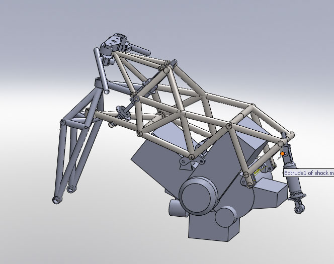
-
Good question Seb. :blush:
I think the lessons learned from MKI are:
1. In frame design and construction you must try and minimise and allow for distortion in the design.
2. Make sure that everything critical i.e. that the steering axis and wheel alignment are spot on and perpendicular to each other.
3. Creating a fixture/jig that will allow you to get into weld tight spots without needing to be a contortionist.
4. That the shock absorbers used are from a similar application to which you are going to use them. (Taking into account there travel and damping characteristics)
The CBR 600 F4i shock I used for the front was a direct acting one therefore over damped for a linkage system.
5. Source and measure everything component before starting construction - if in doubt re-measure several times.
6. When selecting materials for structural parts use the correct grade and condition (heat treatment) for the application. (John Bradley’s books go into great detail on this)
7. Leaving things till later only causes more problems for instance the steering head tube and bearings I used from a Kawasaki GT550 had a specific length limiting the Hossack geometry and forcing the handle bar location to be higher that I would have liked. This also changed the anti-dive effect. When brakes were applied I couldn’t discern any dive which even for my limited experience felt very strange. MKII will have 30mm of dive before anti-dive kicks in.
8. Packaging everything around the engine and location of heat sensitive components can be a headache too. I now have great respect for the big manufacturers in getting everything to fit somewhere!
Things which I liked about the bike were how light it felt compared to my stock 98 and was very stable even with 15 Degrees rake. MK II will be 18 Degrees rake, purely to remove the need to have the drag links back to the handlebars.
-
But the Frankenviffer is stating to seriously look like a Daytona 675.
Yes - a new direction... the 5th Gen lump maybe fairly big and heavy by modern standards, but I'd like to see handle in a smaller package like.. a daytona 675!
If a suitable Eaton supercharger appears on Ebay then i'l be incorperating that too - with no standard airbox and tank to deal with placing can be thought out better.
Bodywork is the other reason - making bodywork is a very lengthy process, this way standard fairings should fit with modification.
Red
-
Thanks Pete, I hadn't planned on using 4130 - just going to stick with 1.5mm CDS mild tube reasoning being that it will bend before it fractures.
Also will be hopefully Tig welding myself this time but using a fixture/jig that will allow almost all the welding to be done without taking it out! Had loads of distortion and miscalulation on my part last time - hopefully the new engine mounts will allow any distortion issues!
Yes i've been using the poor man's CNC too! - but use 3M spray mount to hold A4 paper onto the metal once printed from CAD
MIG - I call it "messy" mig! not a patch on Tig for structural welds - fine for car bodies etc though
Tony's a nice guy - from my experience if your going to send him an email regarding chassis,suspension or anything else make sure you've done your homework first!
-
Easy answer... NOPE... BUT after learning alot from MKI
MKII HossackViffer is slowly developing in 3D (big learning curve!)

Featuring fully revised trellis frame with new engine mount design
new Hossack suspension geometry and fork design
revised/calculated front shock location using CBR954 model (Tony Foale has updated his Funny Front End software to include shock calcs)
Existing engine, swingarm, wheels, brakes, cooling system and electrics will be transfered to MKII (code named NADA)
Been trying to keep my head down reading:
The racing mtorcycle: A Technical guide for constructors Vols 1 + 2
I had hoped to slip on further with MKII before anyone noticed :cool: but then again! :blink:
Red
-
Thank you Jamie. :beer: That info saves me a ton of hassle and will save much expense too. :fing02:
-
Ah Ha! Just asking as I have Tony Foales suspension setup software which when analysing linkage ratios, types and dimensions needs the shock travel length.
I've been using the 57mm travel of a honda CBR954 to give rear wheel travel of 120mm. looks like i'll have to buy one and measure before continuing MK11 hossackviffer. bummer.
Very pleased you pointed this charts error. So thanks again Jamie.
Red
-
FYI - The data for the shock stroke is not correct. This information must have come from Ohlins as they show the stroke without bottom out bumpers, etc. This is not the functional stroke of the shock. Please disregard that information in the spreadsheet!!!
Useful info Jamie :blush: , can I ask where you found out? is it on a Ohlins website somewhere? many thanks. Red
-
Maybe this can be made into a VFRD wikipage so anyone can add measurements of other shocks to the list.
Yep good idea. we could add the mounting type,res location, standard spring N/mm, shim stacks etc.
Any ideas on how to set this up on VFRD forums? :mellow:
Maybe the submission first has to be approved by Slammer before anyone else besides mods and uploader can view the file.This true. It said when I uploaded that site admin would need to vet it first.
-
Just posted this in the VFRD download section: shock_length_chart.zip file is in Excel format
1 for the shock fiddlers out there! Not sure of the original author but much credit to them!
Covers most modern Honda, Kawasaki, Yamaha and Suzuki shocks length and stroke.
http://www.vfrdiscussion.com/forum/index.p...amp;showfile=83
Has 5th-6th Gen VFR dims only, but enjoy! :cool:
-
Liking it, kinda gives it a technical look. :fing02:
-
Wouldn't getting the axis of the upper pivot point closer to parallel with the green axis reduce binding of the scissor joint enough to become hardly noticable? Using a ball joint might result in a bit less direct feel in the handlebars.
Yes I thought so too. Toward higher steering angles the top and bottom of the scissors become non-parallel, hence the requirement for a ball joint.
Still not sure if this linkage system is the most ideal for the application, but lessons are being learnt. Without testing this who knows!
-
After further testing it has come apparent that the lower section of front suspension travel has a self centring effect on the steering (Scissor linkage twisting).
Under the suggestion of Tony Foale, I’m replacing the upper linkage with a ball joint and moving the axis of the link further forward. This ball joint will allow the scissor linkage to remain more parallel and nearer the same axis as the Hossack upright over the majority of suspension travel.
Having the steering axis both concentric and parallel is key to removing bump steer in all but maximum turning situations.
The intersection of green and blue lines shows where the new ball pivot location will be.

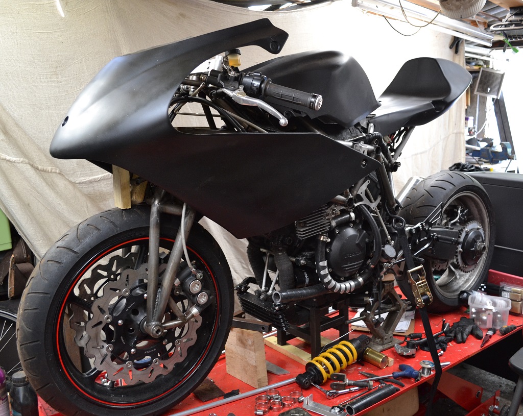
I've been also trying without much success to design the fairing upper.
I’m thinking about using a fibreglass race fairing or existing bodywork and modifying it, as this would save so much time and energy.
Has anyone got any suggestions on what would look good?
-
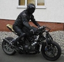
Very impressed, Great to see running, been following for a while, when its road legal you will have to run it over to Box Hill and i would love to see it in the flesh.
Ah, Box Hill a english motorcycle mecca! Been there once before. Are sunday mornings still very busy with bikes?
on another note: I've changed hosting providers in the last 24 hours so some of the pictures aren't working yet - in case you were wondering.
-
Maybe I should start a new business... dressmaking? :fing02:

using calico to work out the seat pattern.
-
Send'em on over! :fing02:
PM Sent! :biggrin:
-
Red, do you have a friendly place to get the parts cut? I might be able to get them done here in the states and then ship'em over to you, if you find the shop costs too high. Once I have a program drawn up I can tell you exactly how long it will take to cut so you can get estimates.
No, not really, guess i'd be paying top dollar here. That would be great Seb! :biggrin: I'll send you what i've done so far. i'd like your opinion on the thickness in some places, especally around the foot rest mounting holes.
-
cheers for the tip HS :fing02:
but i've already fitted one of these:

http://trailtech.net/motorcycle_vapor_kits.html
i'll upload the test ride clip. Bet the playback quality is better on VFRD! :biggrin:
Hossackviffer Mkii
in Modifications
Posted
Thanks Glynn -good to have a sanity check about linkage ideas. Very much agree with your "actually get completed" statement!
You mention that you've built an FFE before? Any chance we can see pictures/designs of it? what was it like to ride?
As to the Chassis list becoming a forum - that's really something i'd like to see (though haven't suggested on list) I would be seroiusly willing to help run one, if the list would agree? I believe a reliable bunch of admin volunteers is the key to HS's success.
PM me if you'd like to discuss further.