


Tightwad
-
Posts
1,689 -
Joined
-
Last visited
-
Days Won
1
Content Type
Forums
Profiles
Gallery
Blogs
Downloads
Events
Posts posted by Tightwad
-
-
tightwad, nice write-up. :fing02:
By any chance, has anyone ever measured the distance from the head of the shaft to the flat machined surface of the CCT body? I'm wondering if there is a difference between a new one and one that is bad.
At what point, extended or compressed? The shaft extends quite far. I am betting the different part number has to do with a different manufacturing area or something. They appears identical to me.
-
Great write up. It seems so easy. Good job.
As a crafty technician it is in my best intrest and the customers to find easier ways to do things. It is not cheating a customer because a technician is bright. If technicians follow the book on every job we would make about $3 a year. Why disturb the throttle bodies if you dont have to?
I agree, there is no sense removing a TB, and potentially disturbing another setting such a cable tension, Starter Valve, etc just because the "book" says to go that route. Now if they are not changing gaskets or replacing wearable parts that should be changed, and saying they are, that is a different story.
-
Yeah, Josh, great thread mate!! But I can't see Flat Stanley in the photos!! Hehehe.
It's good to read this thread, my 2003 VTECker has some 60,000 km on the clock and I'm only just starting to hear the odd CCT noise on letting off the throttle after giving it lots of gas... "blipping the throttle" so to speak. I know the sound oh too well from an old 1971 Toyota Hiace I had way back when... must've changed the CCT 3 times... in one year.
Flat Stanley was there in spirit. It would have been funny to include him in the job, maybe next time. Let me know if Honda Spain is insane on the CCT prices and if so I can ship you the second one I bought if you want a new one. Cost here wasn't too bad...$115 or so for both of them and all the parts needed.
-
Nicely done Tw,
I replaced my CTT's years ago using mostly the same method, but I didn't remove anything but the air box for the front one. That little coolant hose makes it a tight space, but I worked around it no problem. All that's needed is patients and some dexterity and it comes right out! :wheel:
That first time was at 32k miles and with my bike showing 66k miles now I expect to start hearing some noise sometime soon. The rear never seems to go out like the front, maybe because it's on the downhill side of the rear head and always bathed in oil unlike the front CTT. :huh: I replaced them both anyway.
Removing that hose (if equipped with a drain hose in hand) takes about 1 minute, and saves a ton of headaches...I would suggest removing them both, but natually there is more than one way to skin a cat (I prefer Duct Tape and Gasoline....)
I bought both, but the rear is quiet so I saved that one for future install...although next time I am going to try increasing the tension by 1-2 turns to see what it does. Now that I know the process is a 1 hour job at best, it isn't so daunting to put the old part back in.
-
Thanks so very much for putting together this handy guide. I am a procrastinator...I have the new CCT, all tools, and a shop manual but always find something else to do besides taking apart my Honda. Your pics make it simple and are a huge help in motivating me to change this out. I really appreciate the time you spent in doing the write up and taking the great photos. You are a big help to all the VFRD people here. The part # on my CCT is 14520-MCW-013 (I think its an updated one? dunno) , what was your CCT part #?
Again, BIG THANKS !!! for this info ...is very helpful...Doug :biggrin:
(Also looking for an extra CCT KEY if anyone has one they can post me? thanks)
I made an extra "key" out of a small piece of sheetmetal (part of an old CPU power supply actually). I found that when turning the worm drive it would bend this piece...you can see in the picture of the CCT disassembled that it is twisted. I then used the small flatblade screwdriver that I ground the sides down and it worked much better.
I think you have the right CCT part #, I don't have my other in front of me....there is only one choice available now I think.
-
Ok, I am not a writer. I don't have the witty banter abilities of great technical writers who pull you into their project no matter the subject. Instead I am a typical desk jockey who rides VFR and fixes stuff if he can. Before I get into the "easy" way to change the CCT, let me point out that I did not come up with the process on my own. I borrowed bits and pieces from lots of people. The best replacement guide can be found here, CCT change by Rad, where it is done "by the book". In the resulting discussion it was revealed that removing the Throttle Bodies and so forth was a waste of time, as the CCT can be removed without it.
As a second note, I did not change the rear CCT, and I don't imagine I know or could discover any easier way...it seems simple enough already. See the link above to find how to change that CCT if needed.
As a third note (I like notes), I don't believe the CCTs EVER go bad...I think they make noise when the spring loses a bit of tension...more to come on that later (see how I "hook" you...just like the creative writing class said!)
So on to CCT removal and replacement (this order works best I have found)...Anyway, I didn't have music playing, I don't drink beer, and I barely remembered to take pictures....so bear with me. Finding the CCT was the first chore. It is located on the right side, kinda behind and back of the R/R. To find it you need to remove:
Right Fairing
- 8 allen screws
- 1 blind rivet
- Slider (if applicable)
Seat
- Just use the key, and remove
Tank
- two 8mm head bolts, use 1/4" driver
- Restraint Cable
- Two 10mm head bolts at back of tank
Air Box Top
- Hose from top
- screws around perimeter
Air Box Bottom
- Velocity Stacks, Phillips Head Bolts
- Sensor connector on bottom
- Vacuum line going in front of box
- Small connections at the back
When moved, the airbox looks like this:
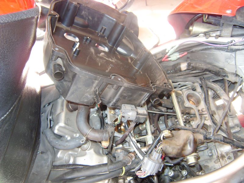
Note the airbox was just rotated away from the CCT. Tank was also rotated the same way and laid across the seat rails. You can see the CCT at the very bottom, just right of center.
Now you are almost there....just need to remove those cooling hoses to make it stupidly easy to reach the CCT. Remove the one pointing out first, and connect a short section(2-3 feet) of 1/4" or similar hose (I didn't measure it, just some I had around, but 1/4" should be about right).
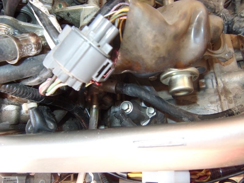
Route this into a drain pan or later you get this:
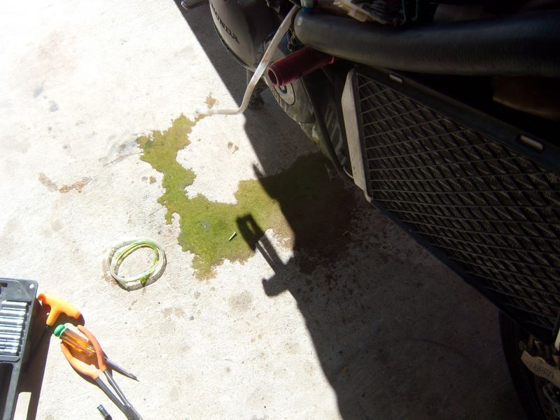
next remove the second hose....this is what makes the first connection take a bit of a leak
not much fluid is lost...a bit more than is pictured here:
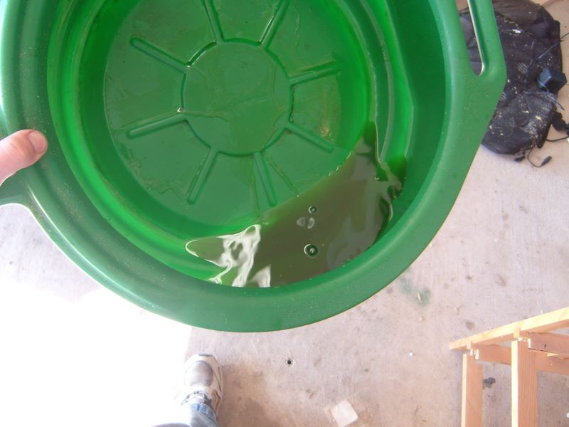
Don't leave this for the dog/cats to drink, unless you don't like them much....
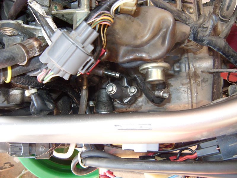
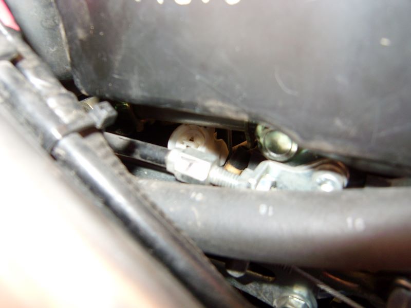
Now it's time to remove that CCT! Simply use your 8mm socket on extension, and take the center bolt out:

This is where the "key" goes in.
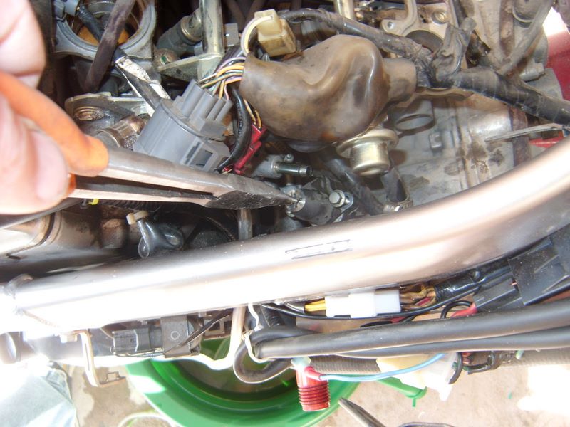
The keys job is to stop the CCT from extending when you remove it from the engine. Keeping it from extending makes it less likely that you knock a bit off into the motor, and also makes it easier for the CCT to clear the various bits above it. If you are really ambitious you could actually rotate the CCT to shorten it and make it even easier...but that would be over kill. After loosing both mounting bolts, and removing them, the CCT just slides right out:
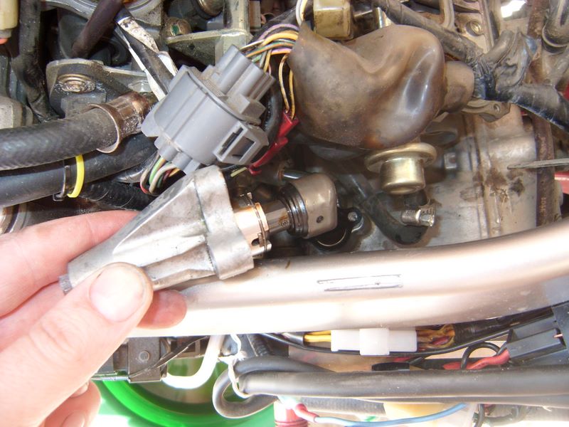
Here is where I have to admit I have a problem. I enjoy seeing how things work. I managed to restrain myself from taking apart my new CCT to see how it works, but the old one was just there....so I had to do it. Initially I planned to try the Reddog idea of tightening the spring....but I screwed up my spring after I removed it, so that was nixxed. Here is a nice picture of my CCT doing it's best Humpty Dumpty impression:
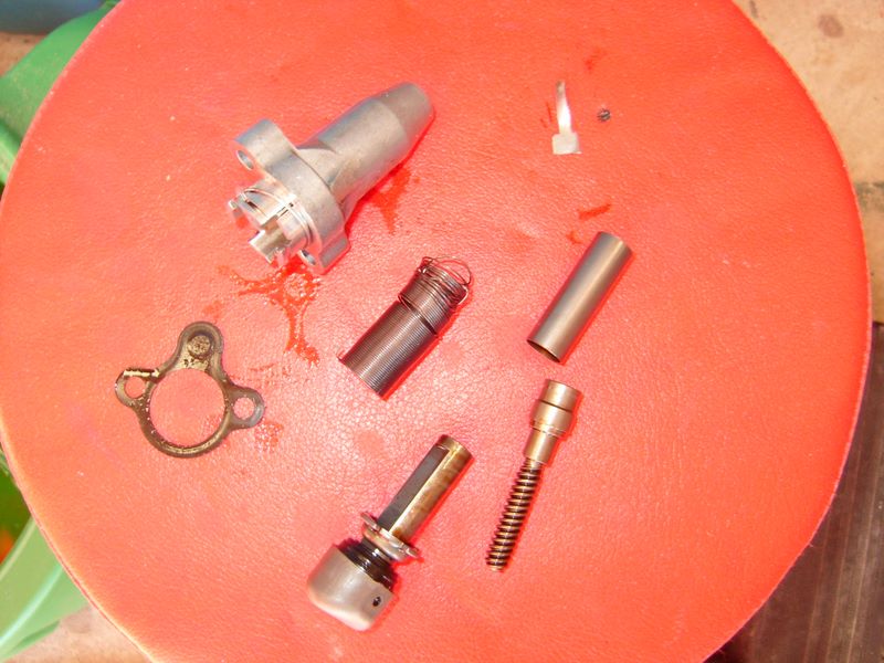
you can see where the spring is messed up....yours won't look like that (don't take it apart to see tho). Let me describe the parts, so hopefully this makes more sense to those who want to know. Those who don't want to know can skip to anther thread or something...
Clockwise starting from the left you have:
- CCT Gasket
- CCT body, with circlip just slid back
- key
- Sping(in the middle)
- bushing/sleeve
- Worm Drive
- Shaft with puck on end
The sleeve/bushing goes around the worm drive, and over the shaft below the locking tab. The locking tab doesn't come off the shaft (without removing far too much).
The way the CCT works is this:
The spring is coiled around the shaft, with one end going into the slot at the bottom of the worm drive, and the other end into a slit at the top of the CCT body. As the worm drive is rotated clockwise, the spring winds up....and if allowed the worm drive will rotate counter clockwise to release tension. The worm drive can only rotate 4 times before the Shaft reaches its stopper. I believe the reason you begin to hear CCT noise is that the spring is able to unwind with a bit of Cam Chain stretch, and thus the spring is not as tight as it was originally. This loosness allows a bit more play that normal, and oscillations begin. Whether different oils help or not I don't even want to discuss.
If you wish to attempt to modify your CCT to save some cash, here is how you do it:
Holding the CCT in such a way that your finger restrains the shaft from advancing, remove the "key". Using a small (probably modified for the purpose) screwdriver, rotate the wormdrive from the access hole clockwise until it stops. Counts the revolutions. It will stop with the shaft all the way compressed. Now reinsert the key, and while still holding the shaft, slide the circlip down so it no longer restrains the locking tab. slide the locking tab carefully up the shaft out of the grooves, noting 2 grooves are wider than the other 2. Then very carefully rotate the shaft counter-clockwise 1-2 times as many revolutions as it took to compress it initially. (this figure is a guess, your results may very, I make no guarantees..written, expressed or otherwise, not available in all locations, subject to rule changes etc). After rotating the shaft counter-clockwise, slide the locking tab back down, and replace the circlip. Re-insert the screwdriver and rotate the gear clockwise to compress the shaft once more. Now you can reinstall the CCT and see if you saved $100.
Reinstalling the CCT is the reverse of removal (I hate it when manuals state that, but it's true. Just check and make sure all connections are replaced or you may not like the results...I didn't.
That is the connector I forgot. The FI light was blinking when I started the bike. I was able to get it back on without removing the air box again using a long thing screwdriver. Speaking of which, here are all the tools I needed to do the job:
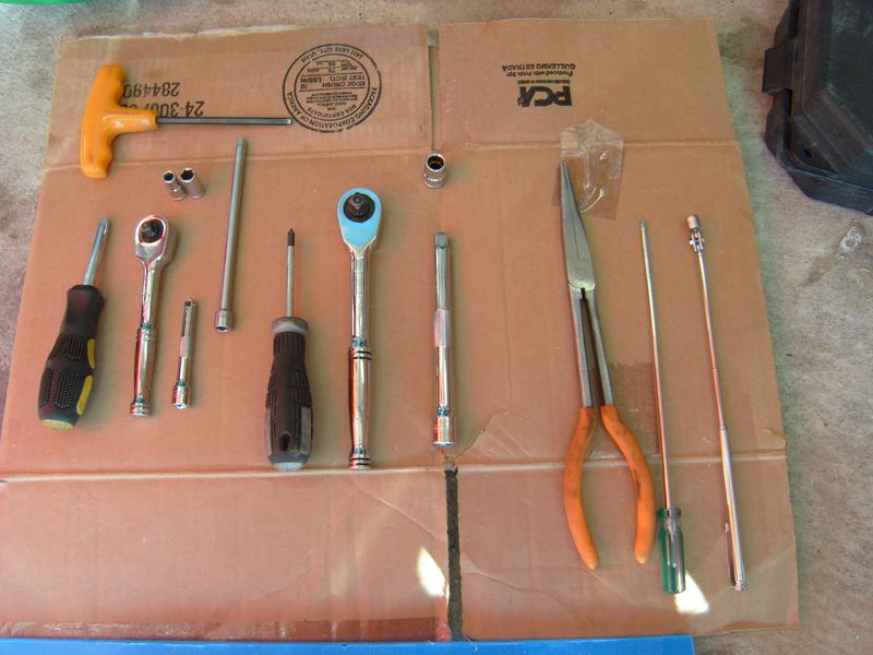
1/4" driver handle
1/4" Rachet
1/4" x3" extension
1/4" x 6" extension
1/4"x1/4" socket for hose clamp
1/4"x8mm socket for CCT bolts and tank bolts
Phillips Screw Driver
3/8" Rachet
3/8"x10mm socket
3/8" x 6" extension
Needed this time, but not always required:
Long Needle Nose pliars
Extra Long thin screwdriver
Telescoping Magnetic pickup tool
Some pictures were not included, you can see them all here:
-
 1
1
- 8 allen screws
-
Ok, I am not a writer. I don't have the witty banter abilities of great technical writers who pull you into their project no matter the subject. Instead I am a typical desk jockey who rides VFR and fixes stuff if he can. Before I get into the "easy" way to change the CCT, let me point out that I did not come up with the process on my own. I borrowed bits and pieces from lots of people. The best replacement guide can be found here, CCT change by Rad, where it is done "by the book". In the resulting discussion it was revealed that removing the Throttle Bodies and so forth was a waste of time, as the CCT can be removed without it.
As a second note, I did not change the rear CCT, and I don't imagine I know or could discover any easier way...it seems simple enough already. See the link above to find how to change that CCT if needed.
As a third note (I like notes), I don't believe the CCTs EVER go bad...I think they make noise when the spring loses a bit of tension...more to come on that later (see how I "hook" you...just like the creative writing class said!)
So on to CCT removal and replacement (this order works best I have found)...Anyway, I didn't have music playing, I don't drink beer, and I barely remembered to take pictures....so bear with me. Finding the CCT was the first chore. It is located on the right side, kinda behind and back of the R/R. To find it you need to remove:
Right Fairing
- 8 allen screws
- 1 blind rivet
- Slider (if applicable)
Seat
- Just use the key, and remove
Tank
- two 8mm head bolts, use 1/4" driver
- Restraint Cable
- Two 10mm head bolts at back of tank
Air Box Top
- Hose from top
- screws around perimeter
Air Box Bottom
- Velocity Stacks, Phillips Head Bolts
- Sensor connector on bottom
- Vacuum line going in front of box
- Small connections at the back
When moved, the airbox looks like this:
Note the airbox was just rotated away from the CCT. Tank was also rotated the same way and laid across the seat rails. You can see the CCT at the very bottom, just right of center.
Now you are almost there....just need to remove those cooling hoses to make it stupidly easy to reach the CCT. Remove the one pointing out first, and connect a short section(2-3 feet) of 1/4" or similar hose (I didn't measure it, just some I had around, but 1/4" should be about right).
Route this into a drain pan or later you get this:
next remove the second hose....this is what makes the first connection take a bit of a leak
not much fluid is lost...a bit more than is pictured here:
Don't leave this for the dog/cats to drink, unless you don't like them much....
Now it's time to remove that CCT! Simply use your 8mm socket on extension, and take the center bolt out:
This is where the "key" goes in.
The keys job is to stop the CCT from extending when you remove it from the engine. Keeping it from extending makes it less likely that you knock a bit off into the motor, and also makes it easier for the CCT to clear the various bits above it. If you are really ambitious you could actually rotate the CCT to shorten it and make it even easier...but that would be over kill. After loosing both mounting bolts, and removing them, the CCT just slides right out:
Here is where I have to admit I have a problem. I enjoy seeing how things work. I managed to restrain myself from taking apart my new CCT to see how it works, but the old one was just there....so I had to do it. Initially I planned to try the Reddog idea of tightening the spring....but I screwed up my spring after I removed it, so that was nixxed. Here is a nice picture of my CCT doing it's best Humpty Dumpty impression:
you can see where the spring is messed up....yours won't look like that (don't take it apart to see tho). Let me describe the parts, so hopefully this makes more sense to those who want to know. Those who don't want to know can skip to anther thread or something...
Clockwise starting from the left you have:
- CCT Gasket
- CCT body, with circlip just slid back
- key
- Sping(in the middle)
- bushing/sleeve
- Worm Drive
- Shaft with puck on end
The sleeve/bushing goes around the worm drive, and over the shaft below the locking tab. The locking tab doesn't come off the shaft (without removing far too much).
The way the CCT works is this:
The spring is coiled around the shaft, with one end going into the slot at the bottom of the worm drive, and the other end into a slit at the top of the CCT body. As the worm drive is rotated clockwise, the spring winds up....and if allowed the worm drive will rotate counter clockwise to release tension. The worm drive can only rotate 4 times before the Shaft reaches its stopper. I believe the reason you begin to hear CCT noise is that the spring is able to unwind with a bit of Cam Chain stretch, and thus the spring is not as tight as it was originally. This loosness allows a bit more play that normal, and oscillations begin. Whether different oils help or not I don't even want to discuss.
If you wish to attempt to modify your CCT to save some cash, here is how you do it:
Holding the CCT in such a way that your finger restrains the shaft from advancing, remove the "key". Using a small (probably modified for the purpose) screwdriver, rotate the wormdrive from the access hole clockwise until it stops. Counts the revolutions. It will stop with the shaft all the way compressed. Now reinsert the key, and while still holding the shaft, slide the circlip down so it no longer restrains the locking tab. slide the locking tab carefully up the shaft out of the grooves, noting 2 grooves are wider than the other 2. Then very carefully rotate the shaft counter-clockwise 1-2 times as many revolutions as it took to compress it initially. (this figure is a guess, your results may very, I make no guarantees..written, expressed or otherwise, not available in all locations, subject to rule changes etc). After rotating the shaft counter-clockwise, slide the locking tab back down, and replace the circlip. Re-insert the screwdriver and rotate the gear clockwise to compress the shaft once more. Now you can reinstall the CCT and see if you saved $100.
Reinstalling the CCT is the reverse of removal (I hate it when manuals state that, but it's true. Just check and make sure all connections are replaced or you may not like the results...I didn't.
That is the connector I forgot. The FI light was blinking when I started the bike. I was able to get it back on without removing the air box again using a long thing screwdriver. Speaking of which, here are all the tools I needed to do the job:
1/4" driver handle
1/4" Rachet
1/4" x3" extension
1/4" x 6" extension
1/4"x1/4" socket for hose clamp
1/4"x8mm socket for CCT bolts and tank bolts
Phillips Screw Driver
3/8" Rachet
3/8"x10mm socket
3/8" x 6" extension
Needed this time, but not always required:
Long Needle Nose pliars
Extra Long thin screwdriver
Telescoping Magnetic pickup tool
Some pictures were not included, you can see them all here:
-
4
- 8 allen screws
-
I'm not really strong on electronics design but I sort of understand the fundimentals. I can't find an internal schmatic of a funtioning pulse generator for an RR but I don't understand why you would put the output to ground. It would over heat the scr and it would put a load on the field.
Well, the purpose of the SCR is to transfer high amounts of current to ground...in the case of the SCRs I am testing with each can handle 35 amps I believe. Usually only one or two legs needs to be grounded to reduce the charging voltage.
The reason you have to ground them is otherwise the Diode would keep passing the voltage. If you tried to just disconnect the power from the diode you would get problems with arcing and such...too much power to switch on and off, so you ground the excess.
As long as your ground plane is good, and you have a way to bleed of extra heat, you don't have an issue. Smaller charging systems also have less of an issue as their initial output isn't that great.
-
24000mi service is $375 just labor... and does NOT include a valve clearance check.
Valve clearance inspections are done at 16k mi intervals... when checking valves at scheduled maint. intervals on VFRs and STs, we almost never have to make an adjustment, as they are 99.9% of the time still in spec.
Hope this helps...
Does Al Lambs stock the the valve buckets or shims or whatever it takes? I am thinking of checking mine, but it is my commuter and I can't leave it down for weeks waiting for parts.
-
The scr's don't go straight to ground in the schmatics I've seen.
If you have some to share that would be great. The only way to limit the charging is to divert the voltage from the Rectifiers to somewhere, and Ground is where they go. If they didn't go to Ground the Rectifier would just keep on charging.
-
My meter only reads to 200, so I stopped here. This means we need an effective way to reduce the output to a usable level....ie 12-15 volts at max. The way it is currently done is by shunting the excessive current to ground. directly from the stator....when output voltage exceeds need, the phase in action goes to ground. This is a similar design to what is used in most Motorcycle Regulator/Rectifiers today:
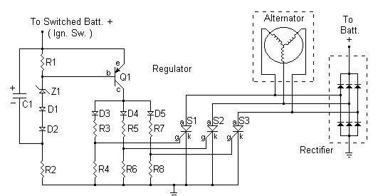
By using an SCR (Silicone Controlled Rectifier) we can control when the grounding happens. SCR's are pretty cool...when set correctly you can trigger them just by touching them....like those touch lamps everyone has played with at some point. Is this the best method? No one seems to have a better one. What is the side effect? The side effect is heat, and lots of it....thus we need a way to bleed off the heat, thus the importance of a good heat sink, including cooling fins and airflow.
Stay tuned, as my next step will be to re-create the circuit above and create controlled output!
By shunting the current straight to ground with the SCR's aren't you are going to put a load on the engine at high RPM? I honestly don't see this as a much better system then the current design. Honda's wiring and components suck. The placement of them on the chassis are poorly thought out and executed. Electrically the original design functions correctly. By design RR's make more heat when there is more load placed on them. Anything that makes as much heat as a rectifier needs to be physically designed to handle it, Honda didn't do that. They only designed it to handle a correctly functioning charging system. As soon as loads increase beyond a properly functioning system (weak battery or bad connections/grounds) it overloads/overheats and fails. Honda got cheap and lowered there quality to the point we have problems with them. The eighties bikes had better designed RR's and the bikes of the time had a lower load on there electrical systems that they had to power. If you look at the eighties RR's they are fully encased in metal with built in heat sinks then in the nineties they came out with the metal box that was potted with epoxy. Now they have gone back to the eighties design.
This IS the current method Honda (and most everyone) uses. There is little other choice actually, because we don't have a "field" circuit that can be activated/deactivated like a car does.
-
...and to those who strap a fan on an R/R, that's the best thing you can do to extend the life of it.
Better yet, relocate it to some location where it gets a continuous stream of 'fresh' air. Doesn't even have to be cool air, as long as it can transport the heat away from the RR.
Ducati acts a lot quicker than Honda as there is a recall for the 1098 & 848 that has charging problems due to an overheating regulator/rectifier. The RR is located close to the exhaust and the fix is that the RR will be replaced and a heat shield put betwen the RR and the exhaust pipe.

MODEL - FROM FRAME NO. - TO FRAME NO.- COVERING KIT - REPLACE REGULATOR
1098 ZDMH700AA6B000006 ZDMH700AA8B018809 YES YES
1098 ZDMH700AA8B018810 ZDMH700AA8B020465 YES NO
1098 R ZDMH702AB7B010185 ZDMH703AB8B016331 YES YES
1098 R ZDMH702AB8B016342 ZDMH702AB8B020314 YES NO
848 ZDMH600AA7B000001 ZDMH600AA8B005624 YES YES
848 ZDMH600AA8B005625 ZDMH600AA8B007708 YES NO
Bron: Motornieuws.nl
Moving the R/R is not easy, although it can be done. The 6th gens don't have near the heat issue that previous models had. 3rd and 4th gen were the worst, because the surface area of the R/R was so small.
As an update, I tested one circuit and didn't have the results I wanted. I did find that they SCR's heated up nice and fast, to well over 130 degrees (they are on a computer headsink, so not ideal). I am hoping to have more time over the Christmas break to play with it, and to try an alternate circuit.
-
This is not at ALL what I understood the resistors to do. The resistor is providing a voltage signal that tells the computer the O2 reading is perfect. This takes the variability out of the air/fuel ratio. The heater circuit is not touched, it is just there to get the O2 sensor up to speed faster anyway.
I'm pretty sure you have it backwards. The resistor is across the heater circuit to fool the ecu into thinking the o2 plug is still present, in order to prevent the FI light from going on. The other two wires are the voltage measurement circuit. These wires are not plugged in to anything, so I'm guessing the ecu will measure a steady 0 volts. At least this is what I gleaned by looking at the wiring diagram in the shop manual.
You are right, as I read through the thread better. I thought the mod made the bike think it was in the right range, instead it keeps it in closed loop mode. The resistors will get warm if you don't use a 1/2 watt resistor or so.
-
Hello to all, I'm new here but have a question reguarding the resitors ( 330ohm/1/2 watt ). How hot are they suppose to get the ones I installed got hot to the touch but not enough to burn and also what size are the bolts that close off the Sensor holes, 18mm is too small.
It's my understanding that the resistors are there to simulate the presence of the heater element in the o2 sensor (the two white wires on the sensor connector), so I suppose that's why they get warm. The other two pins are left unconnected, and present a reading of 0 volts (full lean) to the ecu, causing the ecu to attempt to compensate by going full rich. The power commander then makes the final adjustment to the injectors. Obligatory caveat: I'm not an EE. I just google alot.
This is not at ALL what I understood the resistors to do. The resistor is providing a voltage signal that tells the computer the O2 reading is perfect. This takes the variability out of the air/fuel ratio. The heater circuit is not touched, it is just there to get the O2 sensor up to speed faster anyway.
-
I have contacted Pro Oiler about a group buy...figured it might get us a deal and shipping would be less painful for the US folks at least, and possibly the Canadians as well. I will start a thread in Bargain Finder when I get the details about price tiers etc.
My GF will be glad to hear that! See's gonna get me one for Xmas! :biggrin:
See if you can get it set up to be shipped out in time. :blink:
Depends how late Christmas comes at your house....if people had 3 weeks to opt in that wouldn't leave enough time to ship

-
I have contacted Pro Oiler about a group buy...figured it might get us a deal and shipping would be less painful for the US folks at least, and possibly the Canadians as well. I will start a thread in Bargain Finder when I get the details about price tiers etc.
-
So how does this differ from an automotive charging system, if at all?
Alternators in cars can actually control the Electromagnetic field to stop the charging altogether. This isn't possible on a bike without increased space needed.
-
For those who wish to see the Schematic(s) used, I am including them below. I am testing two different kinds, to see what I think. The first is easily adjustable (before sealing up of course), and the second is adjusted using the correct resistor values.


I have bench tested the first method(prior to Stator hookup, just checking that the SCRs trip as expected), more pictures to come later. I found I needed a higher resistance potentiometer than was specified, and I will be researching why that is.
As a disclaimer, I did not create these circuits.
-
Eastest way to have a pre oiler is to nick the seal behind your countershaft sprocket... you get a running oil
leak that is not only hot but unlimted as well... Honda's old 305s use to sport s screw at the end of the
countershaft that was designed to meter hot oil on the the chain... with the advent of the O ring chain this
was no longer cost effective so Honda dropped the feature...
I can just imagine suggesting this as a serious course of action. "Using a medium sewing needle, carefully pierce the seal on the counter shaft, at the 2:00 position. The correct angle is 54 degrees, and should be done with a red-hot needle (white hot could be damaging)"
I have always said my Jeeps oil is self changing.....7 years ago I actually took the oil plug out.
-
This is a very well detailed description for a non- electrical engineer. Very informative. Well done.
-Disclaimer:
"I'm an Electrical Engineer and I approve this thread"
(I've been overloaded by politics lately)
Good thing one of us is!!
-
Having delt with the rr problem on my 98, I'm still curious as to what happens.
My experiences all point to the connector from the stator to the rr. I've owned my VFR since new and have ridden it 20,000 miles in most types of weather. My suspicion is that over time, the connector gets some moisture from the atmosphere which inhibits a good connection which creates heat which melts plastic housing.
I replaced my original rr last October 07 with one from Electrosport. I had to break the connector getting it apart and ended up replacing the burnt terminals with new ones... no problems during a 4 day, 1500 mile trip. Being the consumant tinkerer, I keep looking for causes and effects. I got a 4 unit Batterytender which I keep hooked up all the time (I also have an SV650 and a VTR). While trying to keep an eye on things, I probably created a poor connection at the terminal block and it ended up melting completely. A call to Electrosport indicated that they were redesigning their rr and would get it off to me ASAP - 2 months went by with no rr! To cure the connector problem, I could either solder the 3 yellow stator wires to the rr or.... use Posi-Lock connectors. I'd seen them reviewed on WebBikeworld (a great site btw) and decided to try them. So far, no issues. I also mounted a small CPU fan to the rr which reduces it temperature by about 20-30 degrees.
Have I fixed the problem? I don't know yet. I haven't seen the fuse or the associated link overheat either.
Mac Morgan
Hockessin, DE
Fixing the Stator connector to a more positive locking type is an ideal fix. If someone had a connector that let you bolt ring terminals together that would allow for the most surface area, and prevent the arcing that occurs and generates heat.
-
I now have 98% of the parts needed to make my own R/R, and test some theories. More to come on this topic as I actually do something.
On a side note, I now know how to make an adjustable low amperage voltage regulator, which I needed to correctly set the on-off point of the R/R. I also obtained some high-amp parts that will hopefully not fry something.
If the purpose of the R/R is to convert excess electricity to heat and heat destroys the R/R, why not separate the vulnerable components from the heat by having a remote electric radiator separate from the R/R electrical components?
The real key is to make it so the R/R doesn't need to bleed off the excess, thus the componets that typically fail (SCRs) won't even have the chance. This was a very interesting read:
A permanent magnet alternator really needs to have a battery in goodcondition connected to the regulator DC output.
The battery forces the system to operate somewhere near battery
voltage.
An almost dead battery forces the alternator to run at about 12.0
volts or less.
A fully charged battery in good condition lets the alternator run up
to around
18 volts before gassing and boiling the electrolyte, if the regulator
fails.
The regulating circuit tries to keep the voltage between about 14.5
and 15.5~16.0 volts, depending on whether it's a flooded-cell battery
or a maintenance free AGM battery.
The permanent magnet alternator system uses a three phase full wave
rectifier bridge to change the AC into DC. You will find a .pdf file
that shows a typical rectifier bridge at
http://www.electrosport.com/electrosport_electrical_home.htm when you
click on the technical links.
If you have an ohmmeter, you can easily do the diode check, but you
would need a variable voltage power supply to test the voltage
regulating circuitry in the regulator.
If one of the diodes is blown out, this reduces the power output of
the alternator by half, for half a cycle. Blow out two diodes and the
output could be anywhere from half power to almost nothing, depending
on which of the six diodes is blown.
In order to regulate voltage, this type of shunt regulator has a
silicon control rectifier (SCR) hooked up between one pair of power
diodes and there is a zener diode that senses when voltage rises above
about 14.5 ~ 15 volts *with the regulator conected to the battery*.
If you try to operate this system with the regulator output
disconnected from the battery, the zener diode will continously tell
the SCR to shunt excess current to ground and the regulator will get
very hot when the engine is running.
It's normal for an SCR or a diode to get *somewhat* hot when you run
power through it, though. That's why the regulator is housed in a
finned aluminum heat sink.
But the charging system of a modern motorcycle is really designed to
burn up excess power that isn't charging the battery by lighting the
headlight and taillights, not by continuously shunting ALL the power
to ground via the SCR.
The best solution would be to avoid riding the motorcycle until the
rectifier regulator is replaced.
forgot to give credit to the author: http://groups.google.com/group/rec.motorcy...6f1bb8cbbdacae2
-
You don't make IED's do you?? :blink:
Wouldn't put it past Dale.... :ph34r: :cool:
Only for fun, and pre-Patriot act of course...although "Improved" would be pushing it...
-
I now have 98% of the parts needed to make my own R/R, and test some theories. More to come on this topic as I actually do something.
On a side note, I now know how to make an adjustable low amperage voltage regulator, which I needed to correctly set the on-off point of the R/R. I also obtained some high-amp parts that will hopefully not fry something.
Carbon Wrap..
in Modifications
Posted
Hmmm, rashed fairing + a couple yards of fabric could = an interesting project!
Now this isn't actually Carbon Fiber right? Just a "look-a-like"? I am also thinking those little panels people mount meters in would be a nice accent spot.....dang I have too many projects and this isn't even along my normal line of thought!