


Tightwad
-
Posts
1,689 -
Joined
-
Last visited
-
Days Won
1
Content Type
Forums
Profiles
Gallery
Blogs
Downloads
Events
Posts posted by Tightwad
-
-
I have made a pictorial for those who wish to install theirs..you can see it here:
http://www.vfrdiscussion.com/forum/index.php?showtopic=35526
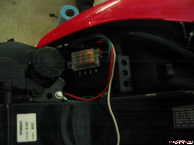
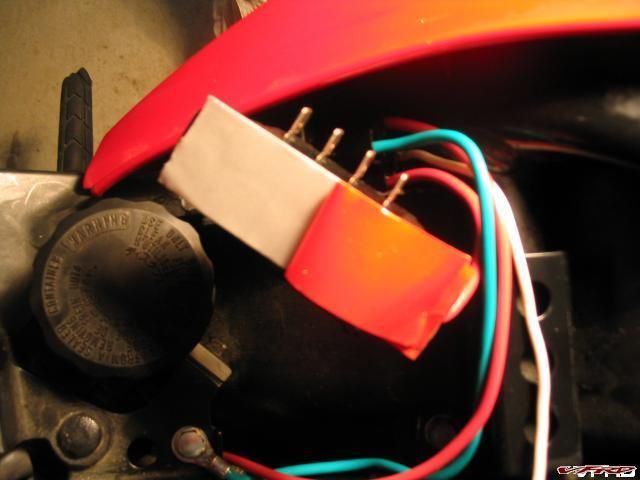
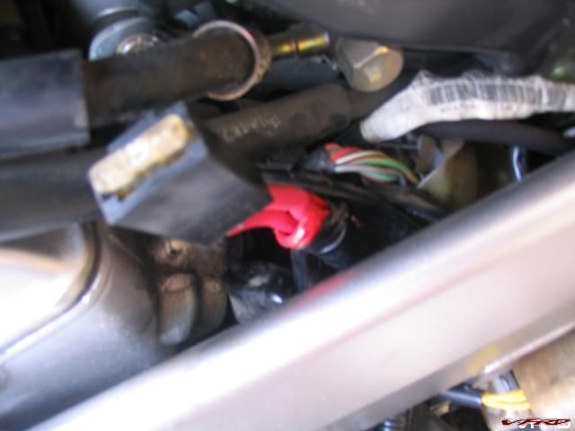
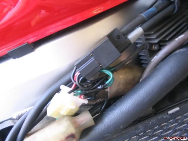
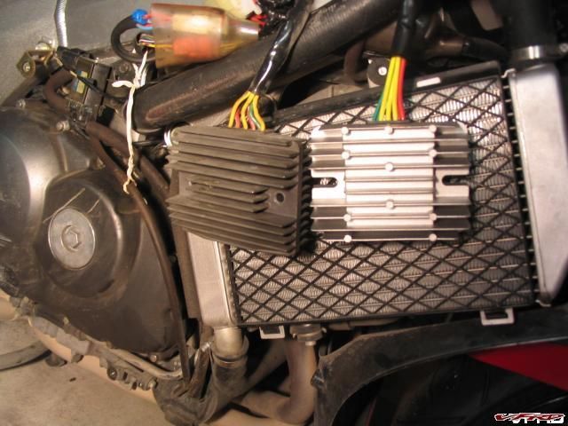
Here is picture of the finished product, relay is tucked behind the panel and works great!
-
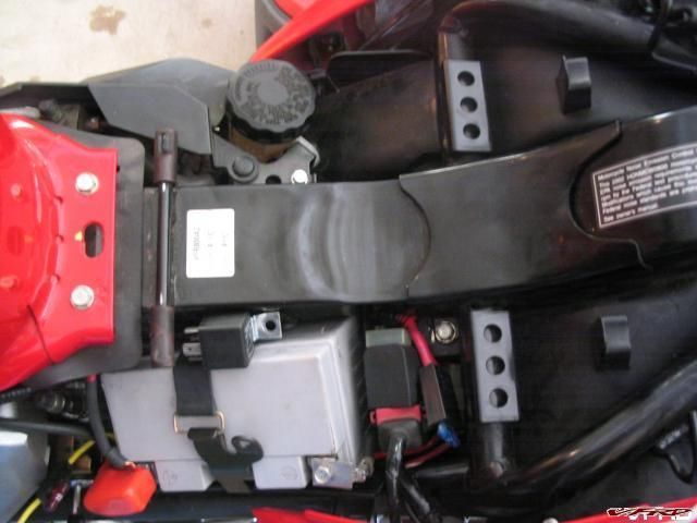
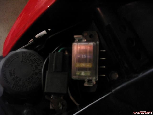
I recently found a great compact fuse panel, which takes care of all my needs. It is rated at a max of 15 amps per line, 50 amps total. Here is the mounting process:
Starting out:
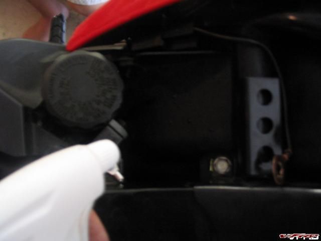
Cleaning the install area:
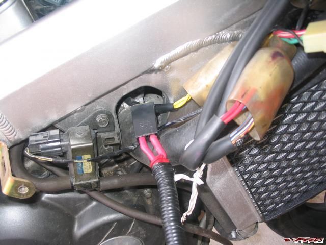
Peeling double-sided tape from Relay to mount:
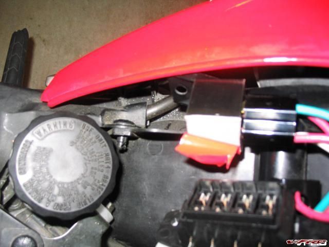
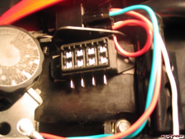
Peeling tape from Fuse Panel to mount
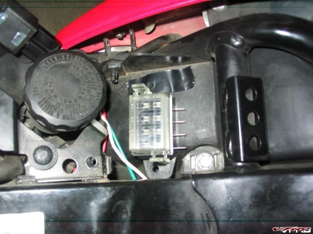
Mounted, note the ground location(green wire):
Fuses mounted, the white wire is my trigger wire, it is connected currently to the tail light, but for those using my harness there is a no-cut option on there:
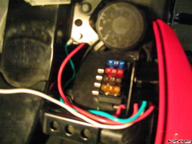
All finished, with cover on. I have nothing connected, but power was present at all 4 terminals just as it should be:
I hope this helps people, especially those with 6th gens and no room!!!
Tightwad
-
Ok, the question has come up a couple times from those who already placed orders, and wanted to add the fuse panel, so I thought I would answer it here(my PM box is almost full):
For $35 additional to the harness(so $75 + shipping) I will include:
a wired relay(connected to the accessory wire on the harness)
fuse panel with inputs ganged together, and wired to the relay
12 gauge wire for connection to battery, with ring terminal
ground wire with ring terminal from relay
All you would need to do is hook the positive wire from your accessories to the flag terminal(included) then the flag terminal to the fuse panel, and install the fuse for it. You would ground your accessory wherever you liked.
I am going to order fuse panels and relays etc based on initial responce. To those who want to add this to their exisiting VFRness order, just let me know. There will be a slight shipping delay (4-5 days) as I will have to wait for these to arrive(other than the 2 extra I have now, which are spoken for already).
-
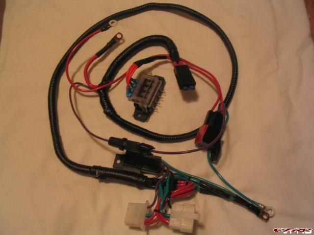
Well.....I decided to throw another option out for those who are interested.
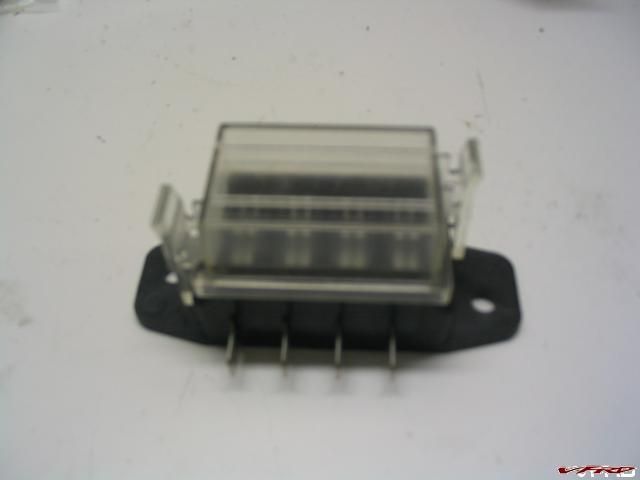
I found a great 50 amp fuse panel(max for all branches), which just happens to fit under the seat on the 2002+ models...I am sure it would fit about anywhere on other models as well. Here is a picture of it:
And here are two mounting options (with and without relay):
I bought 3 of them, on a whim, but I can get more when I order more harness parts.
As far as cost....for those who are ordering the Harness, there shouldn't be much extra shipping, so just the price of the unit would need added. Without the harness, add $7 for shipping in the USA.
4-fuse panel - $15
8 Flag terminals(wires come out the side for tight fit) - $3.00, for $5(total) I will wire one side ganged together so all share an input
Relay - $6
Wired Relay socket - $4
Relay and socket are only needed if you want a dedicated line to the battery. For those running my harness, the accessory wire will power them(or would power a relay). Max amperage suggested is 10 amps if power is obtained directly my harness, 15 amps is the max per line suggested by the manufacturer.
For those not running my harness, tapping into the taillight to switch the relay is a fairly easy option.
I do NOT have these yet(other than the 3 I ordered to see them), but if enough people want them(more than 5 or so) I will add them(and the relays and bits) to my next order. I will also post a seperate thread about them, but since I am offering to ship these with the harness(and because they fit in so well) I wanted to put them here. I have ordered them now.
-
This looks great, but one question.......What does the relay accomplish?
I can uinderstand a heavier wire and better connections so the RR see proper voltage to adjust to, but I'm confused on the relay.
The relay is there for two reasons:
#1. The OEM setup is switched via the ignition switch. I simply replicated that by using the sensor wire to trip the relay.
#2. The relay provides a handy point for adding a switched terminal for other accessories, without having to cut into the harness(and thus introduce more potential problems. This circuit will be fine with low demand devices, or will work well to trigger another relay for something like Heated Grips/Suits or a Video Camera that have higher draws, and should be on a dedicated line to the Battery.
-
I have finalized the price on the Harness system...I need a good name for it....I was able to lower the cost to $40 + $7 shipping for the US. Canada will be slightly higher shipping, whatever the added cost is.
For $47 you get:
1 wiring harness, ready to plug into your 2002 or newer VFR
1 Fused/relayed output wire, in a waterproof quick-connect, which will handle 15 Amps(based on fuse installed in Harness currently, wire/relay is rated to 30 Amp)....THIS IS NOW FREE!!!
1 set of instructions with pictures
Piece of mind that the sensor wire won't cause you problems, and that your 30amp fuse problems are also over.
Also available:
I also have Digital Volt meters. These can be had for an additional $8....I believe everyone should own one! Nothing fancy, simple Harbor Freight tool, but will save you a trip (I use one as a voltmeter on trips!)
PM me for payment details, products will begin shipping in 1 week.
-
My initial fix, prior to developing the harness currently being offered, was to run a fused, relayed wire from the battery to the sensor wire going to the RR. I simply removed it from the plug, using a jewelers screwdrive(any small thing screwdriver works of course) and then used a female terminal to connect. Taped over the terminal so it wouldn't short out on anything and I was good to go. I also replaced the short piece of wire in the 30 amp fuse assembly with a 12 gauge wire and soldered the connection.
This steadied my voltage at 14.37 at 5k rpm, or 14.32 with high beams on. I was still worried about overloading the system, which is when I developed the harness. This brought the voltages to 14.45 at 5K rpm all the time.
-
The installation was very simple:
Remove Seat
Remove Battery
Remove 8mm bolts from front of tank, so it can be lifted up
Remove Right fairing
2 Allen head bolts holding fairing to frame (they have a shoulder on them, so they are different visually when removed)
4 holding fairing to front fairing
2 holding fairing to black part behind the wheel
2 plastic retainers holding left and right fairings together(under fairings) - push in on center to remove (this was a HUGE revelation)
1 plastic retainer holding fairing inside wheel well - push in on center to remove (this was a HUGE revelation)
Unplug connection from R/R to harness (5 wires in connection)
Remove rear bolt from R/R (8mm head, use 1/4" socket on extension)
Starting with the fuse end of the new Harness
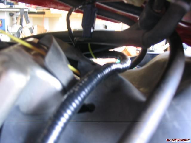
run it inside the frame where the radiator hose goes
next pull it up along the inside of the frame
then along the fuel lines that connect into the tank

From the left side of the bike:
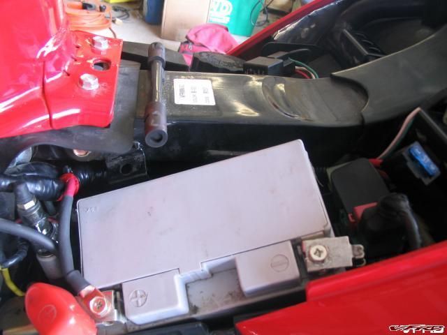
pull harness through to the front end of the battery compartment, here it is looking from left to right, under the tank:
feed harness behind battery compartment, and fuse out by the main fuses

This puts the battery connection next to the main battery connection
Next the right side has to be connected...this is simply a case of plugging in the new connectors, and bolting the ground loop under the R/R bolt.
The relay isn't going anywhere, but it can be zip tied to other wires to make it more secure.
Replace the original 30 amp fuse with the supplied 15 amp fuse
Put the right fairing on, bolt the tank back down, put the seat back on, and you are done.
-
The first prototype has been completed!!!!!
Took me about 5 hours to make, mostly because I was taking careful measurements, testing various options, and continually burning myself.
Every connection is Soldered, then taped/heat shrunk. I was forced to use some button-hole connections which aren't as pretty, but those too were soldered. All power wires are 12 Gauge, ground wires are 14 Gauge(will be 12 in the future, only had 14 gauge on hand for the first ones). The entire assembly is encased in split loom tubing (taped over) for heat.
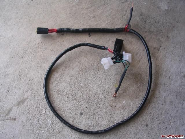
More pictures will be coming, I am off to take my wife out on a date.
-
Still got non-black wheels? Wanna trade?
-
I have ordered the items for the first test batch. I will make 3 kits to start. I have decided to go with option #2, which is a piggy back into the existing harness. Talus suggested this, and I like the idea of two systems working together which in the end gives greater strength. This option solves the "what do I do with the open plug" problem I envisioned as well.
The kit will come with:
2-20Amp fuses, one for the original 30Amp fuse holder, and one for the new fuse holder
1-Wire Harness to augment the existing setup, fully fused and relayed
1-set of directions with pictures to make it so simple my wife will be able to do it
The only tools needed for install will be:
fairing removal tools (allen wrench and small screwdriver for the plastic pins)
8 MM 1/4 drive socket/nutdriver on extension (wrench would work but might be harder)
10 MM Wrench/Socket
basic knowledge of anatomy (male/female difference)
A multi-meter would be helpful for testing the install, if you don't have one I can send one for $15 more that will do the job (I use it as a voltmeter on my bike)
I will have photographs as soon as my connectors, relays, wire, etc arrive. Basically the layout will be this(for those who are interested):
From the Positive terminal of the Battery, an 8 gauge wire(might be 10 gauge) into a fuse.
From the fuse, an 8 gauge wire will run to the R/R area (inside split loom tubing for heat/abrasive protection. The run will most likely be made under the tank, for ease of installation.
From here it junctions into 3 wires, 2 wires piggyback onto the existing Red w/White wires on the R/R plug. One wire goes to the Relay.
The two Green wires will have leads attached at the new connector, and will be joined by the relay ground on a terminal that will bolt onto/under the R/R
The existing sensor wire will be used to trigger the relay. This keeps the sensor wire keyed by the ignition switch.
The new sensor wire will run from the Relay, into the new connector.
If anyone wants to use JUST this wire harness, they simply use a 30 Amp fuse in the new harness, and remove the existing one from the original. I see no reason to want to do this, but the option is built into the design.
More to come, if anyone is a positive on it, speak up for first dibs. As soon as I get a 5th gen to see (and older too if wanted) I will be able to adapt to those years for correct design.
-
I would be interested for a 5th gen, but would like more details as to what problems it is going to fix and would it be compatible with putting in a blue fuse box for future goodies.
This fix will cover the beefing up of the R/R wires(ground and charge) as well as fixing the 30 Amp fuse problem (distributes load through wires big enough to handle it). It will also fix the Monitor wire issue in the 6th Gen. It should solve problems associate with voltages not remaining steady and batteries being overcharged by the 6th gens(due to monitor wire giving incorrect reading).
There is no reason it won't work with the addition of a fuse box for future use.
-
Had to edit costs somewhat, I got more firm pricing on relays and 8 Gauge wire etc. Hopefully no further surprises in store.
#1. $40 + shipping
#2. $45 + Shipping
#3. $60 + Shipping
-
From what I have seen on this and other boards, many of the problems are the same, but manifest themselves differently. Most seem to stem from wiring that isn't substantial enough, especially as it relys on other circuits as well.
On the 5th gens, maybe older ones as well, the Wiring is too small, so the wires cause resistance, which makes the R/R work harder, which makes the Stator work harder....the R/R working harder caused it to overheat. The stator working harder causes it to overheat as well. This is evident in the melted portions of harnesses and plugs. Changing the R/R fixes the issue for awhile, but then it wears itself out again.
My wiring harness will simply bypass(or suppliment) the OEM system, providing additional wires. In the "Beef up dem wires" thread, this was accomplished by cutting into the OEM harness and adding wires. Since many aren't comfortable with doing that, or don't know where to start, or don't want to jeopardize their warranty/risk hurting something, I am building a replacement harness.
If I can see an older bike, to measure the best route for the new harness(easiest to install, doesn't get in the way) I can build one for them. I have a 6th gen, so I am starting there.
I appreciate the input!
-
NOW TAKING ALL ORDERS 1998-2007!!!
After reading thread upon thread, and fix upon fix, as well as doing my own R/R sensor wire fix, I have decided to pursue producing an after market wiring harness. I am tossing around a couple ideas, and could use some target audience input.
Currently the OEM harness, especially in 2002-2005 models has inherent problems. The possible solutions are:
#1. A new sub-harness that plugs directly into the existing R/R, and bypasses the OEM portion altogether. This would be a plug and play replacement with everything needed to just bolt in including a new 30 Amp fuse. Price would be approx $35 + shipping (edited to reflect current cost analysis)
#2. A piggyback version of #1. This would fit into the current harness, disabling the sensor wire from the ignition switch, and running new wires to supplement the OEM Ground and Rew/White wires. This would include everything needed to plug and play, and would come with a smaller fuse installed as it is a supplement, not a direct replacement. Price would be approx $45 + $7 shipping (edited to reflect current cost analysis)
#3. A combination of #1 and #2....you could decided whether to use the piggyback portion, or just the new section. This would have 1 extra connector pair, and would allow you to test the differences by disconnected either the OEM or New harness. Price would be approx $60 plus shipping. (Edited to reflect current cost analysis)
A pre 2002 version would be available as well, with similar pricing, but I would need access to a bike for fitting purposes.
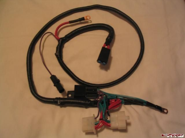
First versions are rolling off the assembly line...errr....workbench as we speak. Harnesses available to cover 2000 and newer bikes. Price is $40 + $7 shipping($22 to Canada) and includes(possibly for a limited time only) a switched accessory wire at no additional cost!!
Please PM me for orders, and specify year of bike in PM.
*NEW*
I found an inexpensive fuse panel, which is compact enough to fit next to the rear brake master cylinder. I am offering this as a pre-wired kit along with my harness:
for $35 (plus shipping if ordered alone) I have everything wired for those getting the harness, just plug the connection together, you can also order it with just blank wires, for mounting without the VFRness. The fuse panel must be ordered with the VFRness for direct compatibility.
This includes 12 gauge wire to the battery with ring terminal, 14 gauge wire from accessory terminal on new VFRness to relay, 12 Gauge to ground from relay, input terminals commoned together to share the power lead, and 4 extra flag terminals to crimp your new accessories onto.
As with anything else, I solder all connections where at all possible.
If someone would like to purchase JUST the relay setup, add $7 for shipping, and the trigger lead will be 3' long, to reach any spot on the bike(taillight, etc).
added 9-13-07:
My website is now online, with most available options. I sell wire, connectors, terminals, tubing, and anything else VFR or Electrical related that I can. if you don't see it, just ask!
WWW.WireMyBike.COM
Update - 9-14-07
I have now received 2 calls from VFR owners who's sensor wire is hot all the time! Why this would be I am not sure, but it means the relay/accessory wire will also be hot all the time. This could potentially drain a battery. I would suggest checking the sensor wire voltage with the key off to be sure it is not energized before installing the VFRness. Should you find that it is, I will send a wire to replace the sensor wire, with a tap connection for connecting to a tail light or similar truly switched source(as the sensor wire SHOULD be).
Update - 9-19-07
Issue with non-switched sensor wire has been resolved, a different wire will be used for activating the relay and providing the R/R with the correct voltage reading. All VFRness's shipped from this point on will be the upgraded model. Those who need the upgrade will have it mailed to them.
For those wanting a clean start, I now have a great item to offer:
Further details can be found here: New regulator
-
I am concerned that your voltage is only 13.5....I think 14.3 or so is the intended voltage. I don't know why yours would be different.
Very nice write up, I was working on one but yours is better....I only did the sensor wire and fixed the 30 Amp fuse part.
-
The best way to diagnose if this fix is needed is to test the voltage at the battery, then again at this connector. The two should be the same. If the RR connector is lower, it will be forcing the RR/Generator to produce more energy than is needed.
Nice writeup Ken, too bad it came a few days too late to save me about an hour worth of looking to find mine. I also relayed mine(the original is switched power) and fused it(the original is fused as well)
-
Just wanted to report back on my fix.
I added a relayed circuit for the sensor wire straight to the battery. At the same time I added an accessory wire so I could charge my cell phone, power a CD player, what have you. I did not mount the accessory wires permanently because I was short on time prior to my trip. I did however use spade terminals to make it simple to disconnect the Cigarette lighter terminal, and plug something else in (tba as to what exactly).
I wanted to be able to monitor my voltage most of all, so I used a cheap multimeter as a voltmeter, and plugged the probes in a modified cigarette plug that I made. I had 14.37 rock solid the entire 1435 miles I logged, except when I used my high beams, then it was 14.31. Seemed perfect to me. I did notice that my battery is now stable at 12.6 after a night, where it should be, instead of 13.2 where it had been....sure sign that it was being overcharged before the mod.
The only scare I had was about 150 miles from home, I looked down at the meter and it was jumping around from 10-14.38 and back....rather sporadic and didn't make sense. My first thought was that my stator was crapping out, or my RR was...not the case. I pulled on the wires my multimeter was plugged into and it became rock steady again....I just had a bad connection.
-
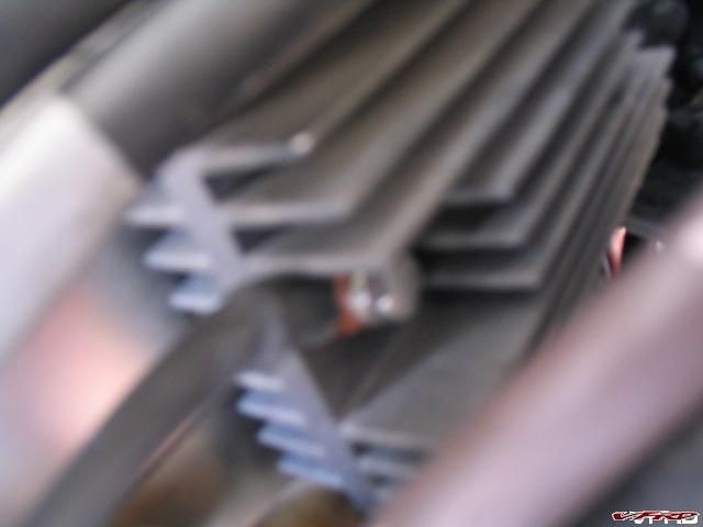
OK, I found the RR after much swearing, and 6 trips into the house. It appears to be located above the Radiator on the right side. It has rounded fins(some are taller than others).
I tested the voltage there, and at 5K RPM got:
15.6 volts from the Red/White wire,
16.4 with highbeams on, and
14.6 V from the Black/White wire.
At idle the Black/white gives 12.9V with High beam, 13.4 without....Black/White never goes above 14.4
I pulled the Black Connector out of the plug, and jumpered it to the positive lead of the battery. This gave me a solid 14.4 volts at all RPMs, with or without the highbeams on. I am very curious what the black/white wire is reading to get those voltages.
-
Ok, I have read this whole thread, and the others like it, twice. My questions should be an easy answer:
Bike:
2002 VFR w/ABS, 15K miles
Current Status:
30Amp fuse holder looks slightly discolored
Volt w/key off and overnight rest is 12.9
Volt with Key on, Engine off is 12.4
Volt with Engine idling is 13.2
Volt at 5K RPM is 15.4, or 15.8 w/high beam
I think that means I need to upgrade the wiring in 3 parts:
#1. 30 Amp fuse needs rewired with 12 Gauge wires
#2. Blue connector, green wire needs bypassed at connector and supplemental ground added
#2. Red/White wires need supplemented from RR to Battery, with 20Amp inline fuses for each
#2.1. Black sensing wire....do I have this on a 6th Gen? Do I need to do something with it?
And the dumbest question....where is the RR located?
Blue connector is on the left side...do I need to remove all panels? I have never had it apart.
-
Where is the best source for the R1 RR? I am thinking I should look into this before venturing 700 miles from home (when all the bad things happen of course)
-
I have owned my bike for just about a month. It's been a great bike, gets fair fuel mileage(37-40 ish) with only intown driving. After a month, that must mean it was time to modify it, right?
I read on hear about someone who made a Brake Light Modulator. Seemed like a nice farkle, and a good first mod. Also seemed like a fun thing to make(I like making things, and had the tools, why not?).
$20 in parts later....I got it! I would show pictures, but I installed it in the subframe(seemed a good location). Here is what I learned from my first time taking apart anything on this bike:
The grab handle bolts were tight....very tight. I would have left the grab handles off afterword, but it seems I don't have the covers. Bummer.
There is no room under the seat for much of anything. Spare mechanics gloves, Tool Kit, thats all that fits!.
For some reason, both brake lights get their power from seperate wires coming from the front. No idea why this is so...redundancy maybe> Not wanting them to flash at different settings, I combined them back together with bullet connectors....I can easily undo the modulator if needed, and I used opposite male/female so the wiring is forced to remain the same(in case that is important to someone somewhere).
Having no room, a project box was a bad idea. Having no Shrink tubing that size, I did the next best thing...I put it in a plastic bag and sealed it with electrical tape. Note to self....do that AFTER you adjust the flash rate etc.....Two bulbs flash different than 1...d'oh. Oh well, I was able to adjust it anyway.
Being as the lights are incandescent, they don't really shut off fast enough. This means the flashing is more of a pulsing....still stands out very well. I slowed it down alot from my initial settings to get a more pronounced flash. I set it to flash 6 times, then come on solid.
Spare Electrical pieces are helpful. 10 full sets is overkill. I think I will have to make some more....want one?
Installing Compact Fuse Panel
in Modifications
Posted
It already is, $35 for the whole kit ready to bolt in(includes 4 additional flag terminals for connecting accessories. Save on shipping if you order with the harness.