


Auspanglish
-
Posts
2,307 -
Joined
-
Last visited
-
Days Won
28
Content Type
Forums
Profiles
Gallery
Blogs
Downloads
Events
Posts posted by Auspanglish
-
-
Well I have downloaded an alternative browser (Firefox) onto the smartphone and created a permanent exception to the certificate issue and can visualize all images. Using Firefox to write this.
Pity about not being able to see it all on tapatalk as it's so much easier faster and convenient to use for forums.
-
I did get the certificate warning and selected "enter at own risk" or whatever the wording was.It's down to the site having an untrusted certificate issuer. Symantec did some bad stuff & a bunch of browser makers including Google said they would ban Symantec certs. So Symantec sold their cert business to Digicert, but any issued certs still carry Symantec as the CA & that is NO longer trusted, so it barf's in many browsers !
So I just have to suck the pus? -
I'm not seeing the pics peeps post when perusing using Tapatalk on my smartphone. In fact I can't even get VFRD to work on my smartphone internet browser and can only see people's text on tapatalk.
So I've tried all the tricks this old dog knows:
Wiping cookies, browsing history and all other things wipeable.
Updating versions of both tapatalk and web browser.
Clicking out and signing back in.
Turning phone off and back on again.
Checked out set up options in case images were not to download automatically to save megas (but should get option to click on them and download manually and don't).
The other forums I frequent work fine, both on tapatalk and web browser.
Any suggestions?
HS do you have a rabbit up your sleeve or a card in your hat?


Just checked, I can see my own images.
In fact I can see some other people's images as well, if I'm not wrong it's ones they might have uploaded to a VFRD gallery that I can't visualize? Is that possible?
-
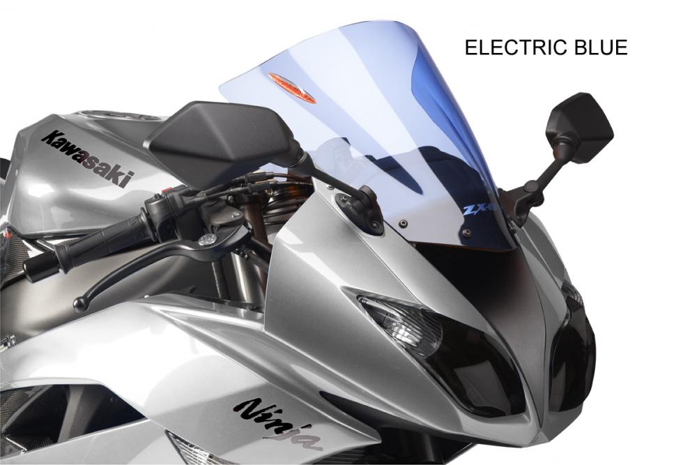
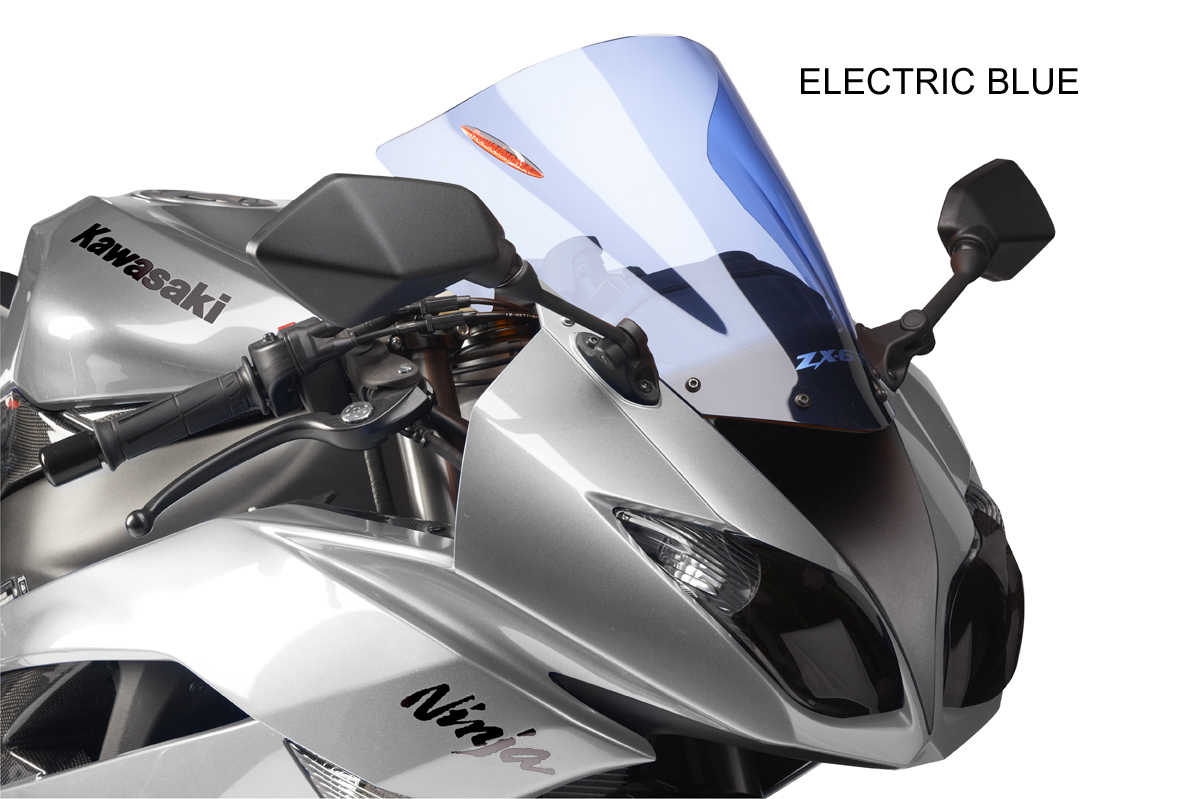
Not sure if it's my phone but I can't see these images and can't even get on VFRD via this dumb phone's web browser...And courtesy of Powerbronze, the Electric Blue (will match my Iridium Cool Blue screen)
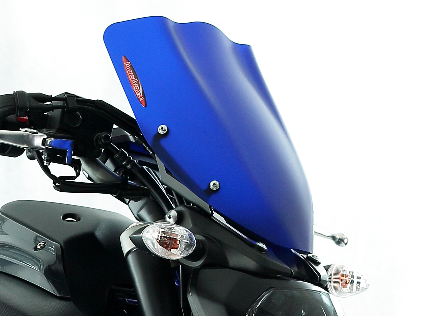
and the Sapphire Blue:

-
AffirmativeSo after looking for grounding cluster (for days) somewhere near the battery, now I know better. On my 2002 front fairing is going off tomorrow!
But just to clarify. I am still waiting to hear from Honda (Australia) to hear if front harness recall has been carried out. If it hasnt, i wait with this mod? Correct?
And then on new or old harness I solder all together, and a thick gauge(?) wire I then lead to any nearby bolt, on the chassis?
Not just stupid, old as well.
Trygve
-
Scarey stuff...
Stopped at Headington shops to get some gnosh for the next couple of days I have off and on returning to the bike and putting my wares into the very convenient topbox this bike came with, a rather vertically challenged and morbidly obese lady with not just eccentric but God-awful ecclectic taste in clothes, Freddy Kruger nails painted vino tinto red and clown-smeared lipstick, approached me suddenly, crossing the street without checking for traffic (cars screaching to a stop to avoid law suits for running her over, sorry to avoid her coming to any harm)... the lady (presumibly) starts spouting accolades of "what a lovely bike" and before I could get my helmet on and claim 'unintentionally' hampered hearing, and between unintelligible comments and questions that found me repeating "Sorry, what?" an awful lot, she states with supreme confidence that my bike had been parked in front of the Angel & Greyhound (pub) last Saturday at midday (about 7 miles from where it was today)... which, astounded and now somewhat concerned for my own safety, I admitted it had been.
> 'Lovely bike... it's one of those (unintelligible word) bikes isn't it?"
>> "Sorry?"
> "Oh nevermind I've made some poor decisions over the course of my life unfortunately. It really is a lovely bike"
By now I've put my helmet on and make gestures to the fact I'm having trouble making out her words.
> "I dont wish to pry into your private life but you do realize..." her eyes giving her thoughts away as she glanced to the ground below the bike.
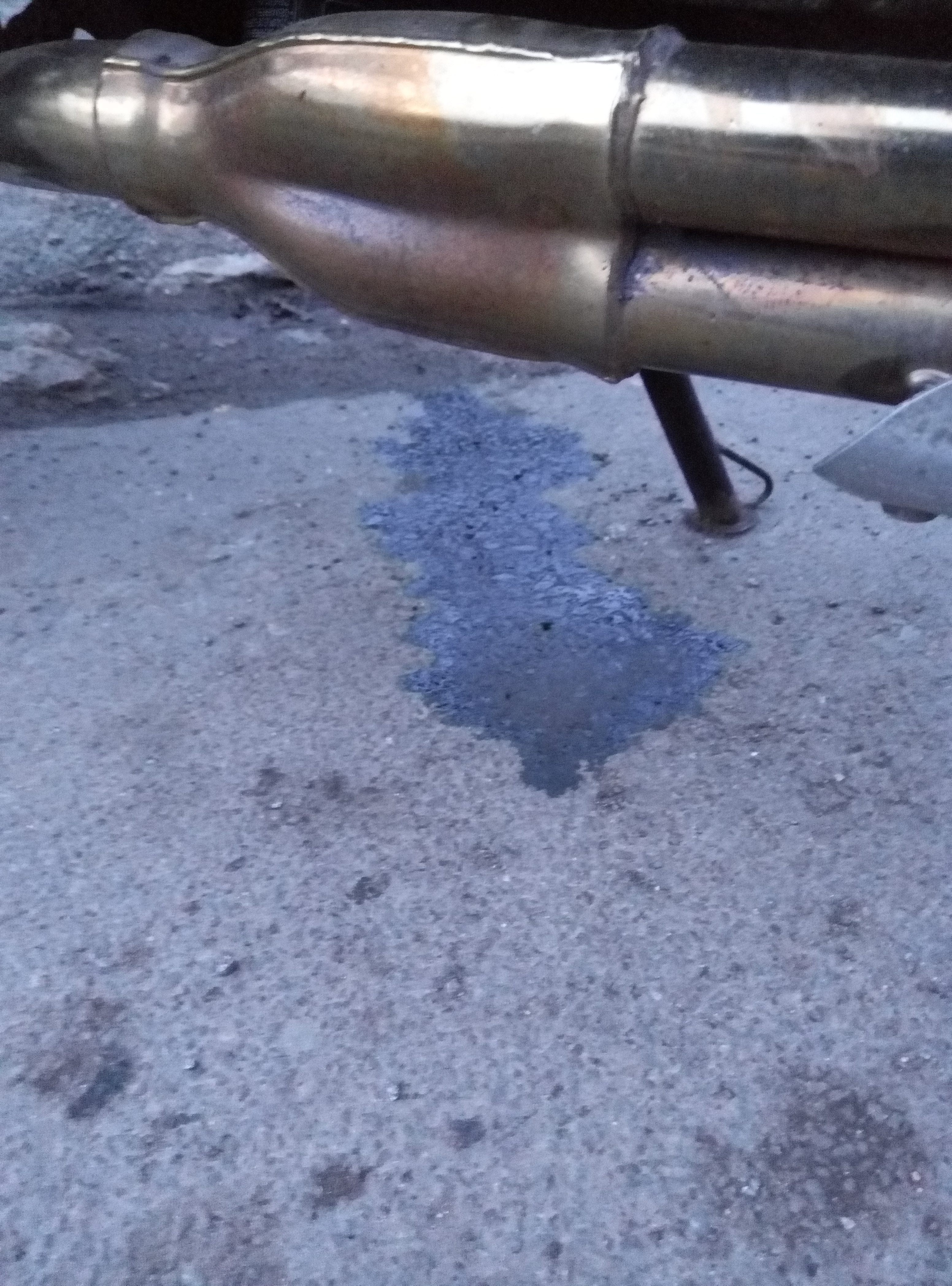
>> "Yes I know" I interjected (I had seen the small puddle on occasion lately and just now on approaching the bike and have booked the biked in to the mechanic's).
> "...you're leaking petrol, do you not?""
>> "Yes, yes. I'm fully aware, no drama, getting it fixed."
> "It's the bottom right bolt not the other one... absolutely lovely bike!!"
>> "I know I know... well I must be going..."
> "Oh I do apologize... lovely bike!!"
She actually put out her hand in an obvious way, so I rapidly and lightly shook it, wished her all the best and then, determinedly, mounted the bike, turned the engine over, flipped the blinker and merged into traffic.
These Triumph Tigers are chick magnets. Psycho-freak-crazy chick magnets but magnets all the same!!
Rode off wondering why hadn't it been the tall, leggy, tight-jeaned, tanned, blonde pony-tailed, blue-eyed attractive one who was coming into the supermarket as I was leaving and made eye-contact with me, instead of the bag lady.
Is it me? Is it the bike? Is it the full moon?
More importantly, should I lock the windows at night?

-
Photobucket is a misleading title, not useful for key word searches on topics.
Just by the by -
That rod is also prone to bending and deforming if you're doing other stuff in the general area, like syncing the starter valves. Pretty hard to get it perfectly straight and true again without a bit of know how or trial and error.
As to causes for overheating, could be thermostat stuck closed. Could be faulty reading (sensor fail or air trapped around sensor).
If fan not coming on there are several possible causes.
1. Fuse
2. Most common is air trapped around thermoswitch (top leading edge of left radiator).
3. Fan motor kaput, just ground the wire coming from thermoswitch and if not spinning, swap fan.
4. Broken hardened wires losing continuity
Etc
-
 1
1
-
-
Tigress booked in with Hughenden M40 Triumph mechanic for a few mods, reps and preps prior to trip to Spain in April.
Went in person, spoke with Bruce and the mechanic, we went over the bike and I am convinced they know their stuff and have been enjoying and tinkering with Triumphs for decades so feel confident booking her in. Usually do all my own maintenance but currently don't have access to space, tools or time. They were congenial, transparent, knowledgeable, professional, observant to detail and even helped / showed me how to adjust seat and got their hands dirty. No signs of smooth talking, shoddy, slight of hand, bullshitters who will take you for a metaphorical ride.
Of course that could be a wrong impression and I get a steep bill and find bits falling off as I ride out the gate but I think I'm a good enough judge of character. Mechanic seemed very aware of each model's quirks and the creative solution to them.

Sunny day for a change

-
Why procrastinate now when you can do it later?
-
1
-
-
They're installed upside down to each other... If that makes sense... To tighten chain on 5th you turn the eccentric the opposite way to the 6th gen.
-
Welcome.
I thought Oxford was ON the river, where the oxen used to ford it, to be etymologically correct. So south Oxfordshire would be technically south of the river.
Hehehe.
What would I know? I'm an Australian from Spain with a Triumph living in Oxford.
OK so some call it the Isis but it's the same river.
-
I would definitely do the common ground connector fix on the front subharness. On post 2005 models it's the orange connector in the plastic hoody cover where the big blue and grey connectors are. If you remove the left side fairing panel you'll see them just near the forward edge of the radiator. The green ground wire going through the blue connector can also be future proofed by splicing and bypassing the connector and reinforcing to the chassis. Reinforce the common ground bus cluster of green ground wires to the chassis when eliminating that crappy orange connector and solder the lot together (or solder them into the metal male/female grid that's left when removing the orange plastic holder) by running an extra wire to the chassis. Then some would eliminate the Stator to R/R connector (3 yellow wires along top edge of right side radiator) by replacing it with a quality ceramic connector or directly splicing is a good idea.
I believe I have a thread called BYC Kentucky fried connector or to the effect. There's another thread titled Eureka or Eurethra which focuses on the same common ground bus connector but on the 5th gen. There's a link in there to my thread. Then there's also a thread titled "The Drill".
Same crappy Honda wiring I'm afraid.
Dodgy wiring around the battery area as well if you're anal.
If all that fails, VFRness might help.
-
Nice
In terms of all these clickbait titles popping up like the mushrooms being popped by some... Perhaps there should be one sole generic "What did you do to your VFR today?" thread and that's it, but personally I believe there should be none.
The title is meant to allude to the subject broached in the thread. Helps with later searches for particular information. Otherwise it's like a library which stores books randomly.
Any opinion from the board of moderators and administrators?
-
What equipment do you wear, including boots, gloves and helmet? Any other accessories? Heated components beyond grips? If so, Where do you plug them in?Rode another 102 mile commute, some of it in freezing rain, with absolutely no issues whatsoever.
-
Where'd you get the seat done Woods? Turn around time? Did you forward a second used one to save on down time? How much did it set you back? Would you recommend their work?Ha... I may grow OLD but I refuse to grow UP! .
that being said I have modified the Viffer for more comfort. higher bars, softer seat for my ageing posterior. and I am relatively young.
-
You need to powdercoat the chassis, forks , footrest assemblies and Sebspeed clutch window bits in the same gold as the rims to really set it off!!

-
1
-
-
Dude if you could paint or powdercoat the chassis, forks and footrest asemblies in matt black, it would truly be stealth under the radar stuff!!

-
You know I speak perfect Spanish, spend time in SE Spain and may be returning there "permanently" some time this year. Have good MC buddies all over Spain. Anything I can do just shout!
Best mate's brother in Valencia used to ride motards... and he (my buddy) does all the maintenance on virtually all our MC mates' bikes, his brother's included so he should be a mine of information... -
Sorry, maybe I was stating the obvious. Didn't mean to offend.
So it takes longer than that to stop misbehaving? Disappointing to say the least.
Fuel injected bikes do tend to be much jerkier compared to carbureted ones.
Otherwise maybe the wax idle unit has air trapped in the coolant line?
-
Something shortcircuited to ground?
Multimeter to test for ground where it shouldn't be, starting from the bulbs and working backwards?
Or maybe a relay is sticking?
-
The VFRness is an excellent product but there's a thread on here somewhere called "the drill": nothing like having the original loom in optimum condition and the known typical gremlins future proofed.
-
Just ride it and post pictures of interesting scenery with the bike in the shot. Tell the story of the ride.
A few ponies here and couple of Newton metres there, much of a muchness. The biggest improvements on the new gen would be front mounting radiator and no more Kentucky fried stators.
I can ride your bike faster and I haven't even tested one yet.
-
Turn motor over first. Then put on riding gear. Quick safety check tyres, chain, etc. Make sure you've got your wallet, mobile and keys. Kiss your wife, girlfriend, lover goodbye. By then the bike's warm enough.
VFRD now worky thanks!!
in Site Comments, Help, & Support
Posted
Hehehe