

JAM
-
Posts
45 -
Joined
-
Last visited
Content Type
Forums
Profiles
Gallery
Blogs
Downloads
Events
Posts posted by JAM
-
-
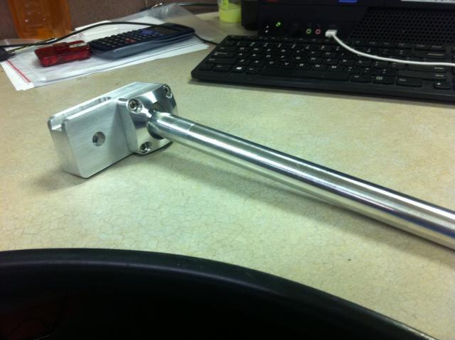
I have had a need for a while now regarding the positioning of my hands on the bars. I wanted a more fluid way of fine tuning where the bars should set. Here is the right side, unanodized, and partially tested for strength. They may look like they would move, they won't. The ball and socket have been cnc machined, and some more pocketing is coming down the line. The bars are solid, and I am even going to redesign the grips in an oblong cross section to eliminate the numbness my hand goes thru sometimes. It is weird I know, but new is that way sometimes. It will intergrate it into the triple clamp I posted earlier.

-
 1
1
-
-
Those look really cool!!! Streamlined and functional!!! I like the color, and adjust-ability, plus with the turn signals up so high, it should make it easier for the cagers to see you in their rear view mirrors. You said that you weren't sure about blinking, or steady on. If you have room, why not put the clear LED's below some orange LED's. The orange ones could be used for turn signals. I'm terrible with electronics, so I'm not sure how that could be managed. I'd have it set so that the white/clear LED's would go off when the ornage turn signals came on, hopefully increasing visibility. How difficult would it to make the support arms in an airfoil shape?
Thanks for the comment. I made the mirrors small, but replaced the flat mirrors with convex glass for a better field of view. I have the bar ends as turns, and think that I will leave the mirror's amber LEDs at constantly on for better cage visibility. The arms were machined out of 6061. I could get a bigger piece and shape them using radius cutters or I could just get a piece of round. Their profile is small enough that I don't worry about turbulence. neither from the mirror or the mount. I read about motorcycle aerodynamics one time. Stated was that a brick with one end rounded would be more aerodynamic trailing the smooth than leading the airflow, all based on the turbulence. I am going to run some tests for vibrations and have some hair brained idea to use water as the dampening element. If I get that far I will show it.
-
My first reaction when I looked at the pic 'Wow, what the hell it that?" But after staring at it for a minute or so, I think it looks pretty good. Nice job. :fing02:
Better to be looked over than over looked. It is hard developing something new without stepping on traditions. I always start off with my list of needs, and try to follow some basic design guidelines regarding strength of materials, functional needs, and long term wear and usage. Sometimes I am surprised at the ending. I am a mechanical designer who uses no program or paper when I make things, funny how that is. Sort of a stream of thought. I posted these pics and descriptions to see if the design could hold water, so questions are very much appreciated.
-
Looks like a cool idea. I'd open the larger pictures up but they're 3MB ea, can you downsize them a little?
I kept them big so you could see them up close and criticize :). I just dumped them, if it becomes a problem for many I will downsize.
-
Nice workmanship and clever idea. They do look a bit bulky though. Is there such a thing as blue delrin? That would be pretty neat.
They are taller that I would like. They are prototypes, so the even the springs had to be cut and ground. They have to protrude a bit in order to push and release the ti washer. I guess what I like most about the clear bobbins is that that they are unlike other fasteners, most people would not know how to take them off. The black ones are high also, but taking in account the cap screw height, lever thickness, and the need to keep some material around the pin, I kept them at that height for those reasons. I used ABS because they could be painted if needed. I would advise against delrin, and yes I have seen royal blue delrin. A lot of nylons are not suited for the outside. They swell and degrade under UV conditions. The overall look is a bit unusual, but as a whole they don't stand out looking at the bike as a whole. Thanks for your ideas.
-
Wow, and I thought I went through trouble when I bought 1/4 turn fasteners from McMaster-Carr.
Those look like the fasteners on my old VFR (1990)!
Which one, and how, that would be funny, me 20 years late. Or is that normal?
-
Tits!
What I missed is the reflector in the bar-ends. Are they lit, as well? Like it!!!!!! We should brain-storm 6th gen trinkets! LOL.
The bar ends have turn signals integrated into them. The bar end are stainless and purchased from Polo GMBH in Germany. They make them in brushed, shiny, or even black now. I will look the company up later. What other trinkets are left? I did do the not so sexy rubber flap on the inside that is attached to the rear inner fender. It does very cheaply what the hugger does, that is keep the crap from being thrown into the rear shock. I will post it in a short while. PM if you have anything else.
-
Wow, and I thought I went through trouble when I bought 1/4 turn fasteners from McMaster-Carr.
I think the DZUZ or something like that were an inspiration, but I wanted something nicer and reversible.
-
The only thing they're going to protect back there, is the engine cover. It's been said, with regard to a brand of sliders that mounted in that same location, that they may actually cause extra harm by being there - for two reasons:
1. They're closer to your leg in the event of an accident
2. Being that far behind the central weight of the bike, they can actually allow the weight of the bike to lever the upper side fairing harder into the ground, compromising them and the even more expensive bits behind them.
If you want the most effective frame sliders, they need to be mounted farther forward where they'll take the brunt of a tipover/slide. Unfortunately, that means drilling holes in your fairings too.
\
Thanks for the input Seb, but in the event of a tipover, they have done more than protect the engine cover, they've protected the side fairing, this by way of a true life experince. As much as I have done in the riding department for 25 years and never crashed, I have had a few tipovers. I would imagine that in an accident where the bars could be a problem, the motorcycle itself, or the thing that is going to hit you is a greater problem in an accident than that rounded piece of nylon. In the event of a slide, the nylon would snap and what is left is nothing higher than the engine cover. I've seen the bike fall, I've picked it up, and examined the damage. I would make them again based on what i know.
'
-
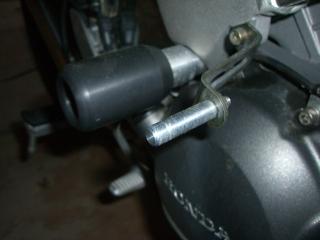
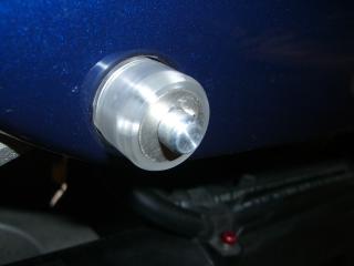
I like modifying, but I don't like to change the basic structure of the bike. So I ordered a while ago some white Nylon and manufactured some sleeves and an aluminum standoff. In short they worked when the bike was loaded up with hard sides and I was knocked off balance. The prototypes worked when the bar ends and the bobbins kept the bike from scratches and breakage. This pic is not focused, as I forgot to include them in my new mods. These new ones are better in the UV and moisture resistance, and I filleted the the ends because I could. The are close to my shins, and might aid in the slightest in the event of a collision of a smaller event. They are there mostly to protect the plastic. Thanks for reading.
-
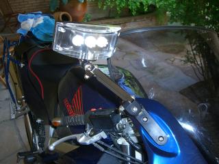
I like some others catch bit of their shoulder in the mirror. I could adjust the factory mirror to where I liked. So I machined another set out of 6061. I know that they are a bit peculiar, but they work. I cut the mirrors out of a convex mirror and ground them to fit inside the black holder. The clear acrylic body holds three bright LED assemblies, turn or constantly on, I don't know. The mirrors articulate high, low, or anywhere you need them to be. They have bushings of brass, hardware in SS, and all aluminum surfaces are black anodized. I still have old OEMs, but wanted something I don't want to curse at. I supported the mirror in the middle so as not to have the mirror fold in at higher speeds. This forces the arm to be a bit longer. The arms have a black acrylic cover which covers the power wire to a point. I am going to change the wire to black in the near future.
-
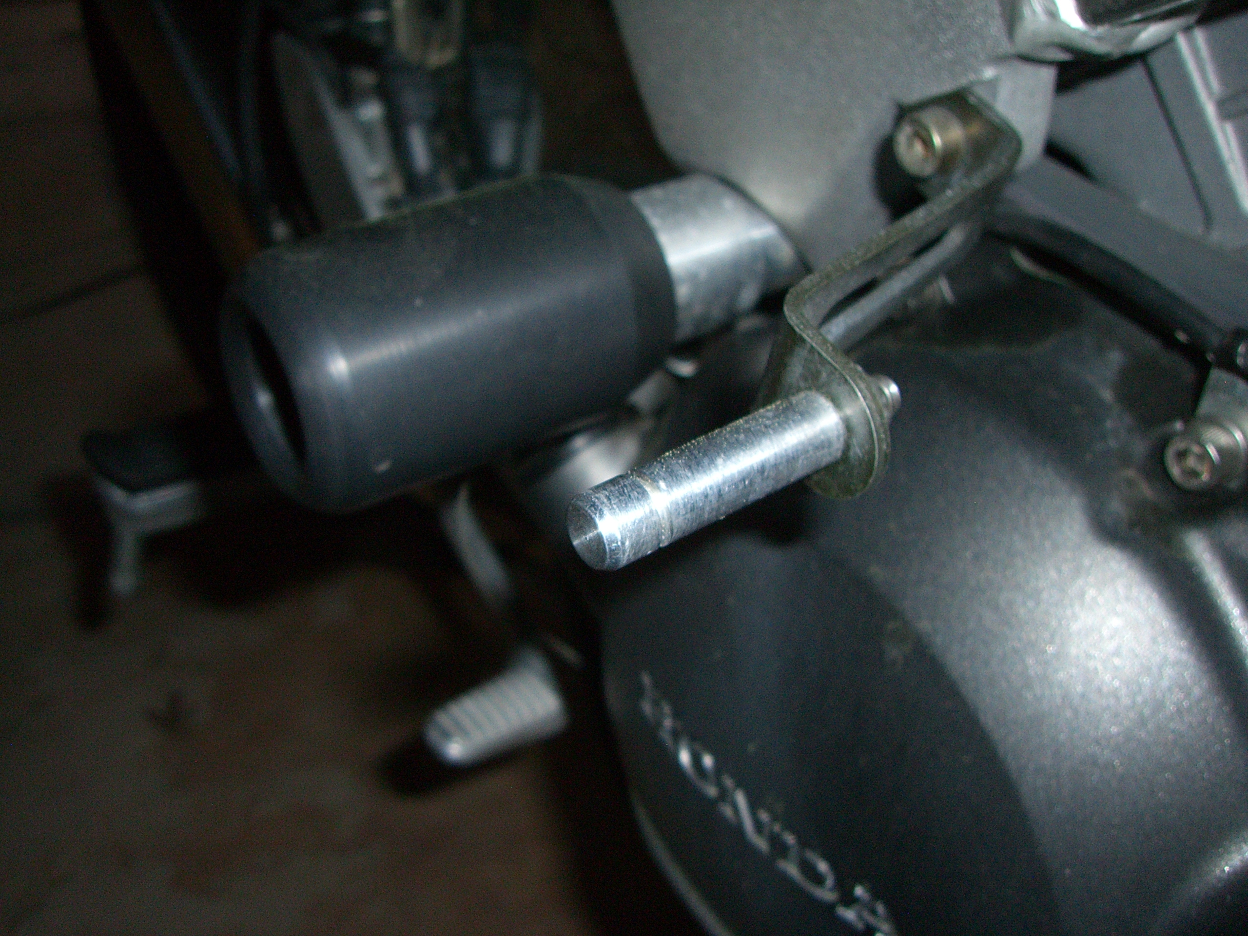
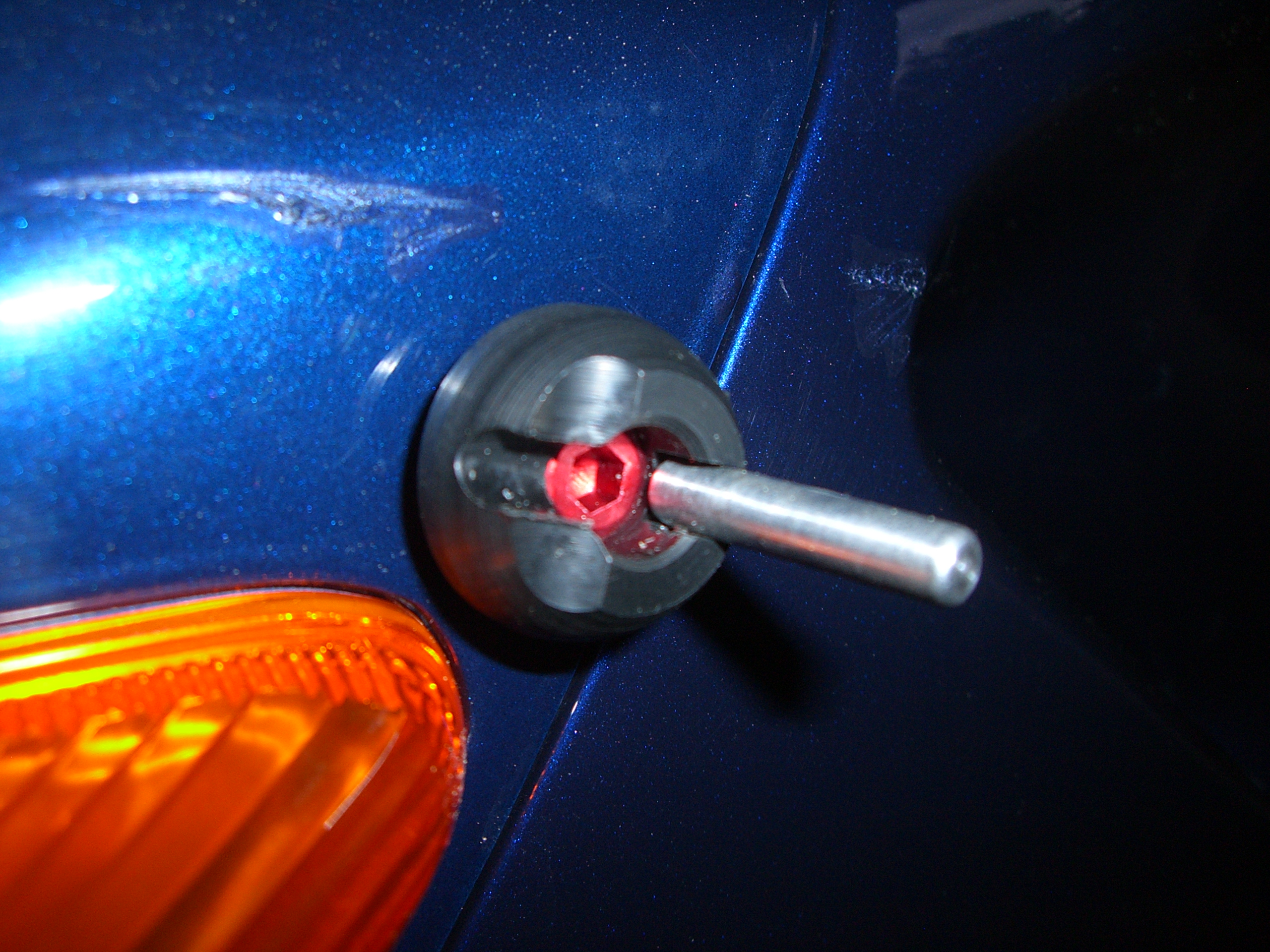
I would guess this idea sprang forth when I scratched the paint holding or inserting a driver to take the fairing off. I liked the DZUS method, but wanted not to modify the fairing to such an extent. So the lathe, mill, and I decided to manufacture a lightweight bolt that had leverage but could be minimized. I had some anodized cap head screws, some ABS, and McMaster on the line. The aluminum rods are not anodized, but will be. The are held into place with stainless split pin. The lever rod swings out to crank it like a handle, fully for leverage, and finally it snaps into a closed position. The contact surface has been filleted to compensate for the inset holes in the various fairing pieces. I cranked down on all of them to a point, and only had one problem where the pin wasn't centered.
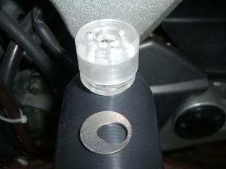
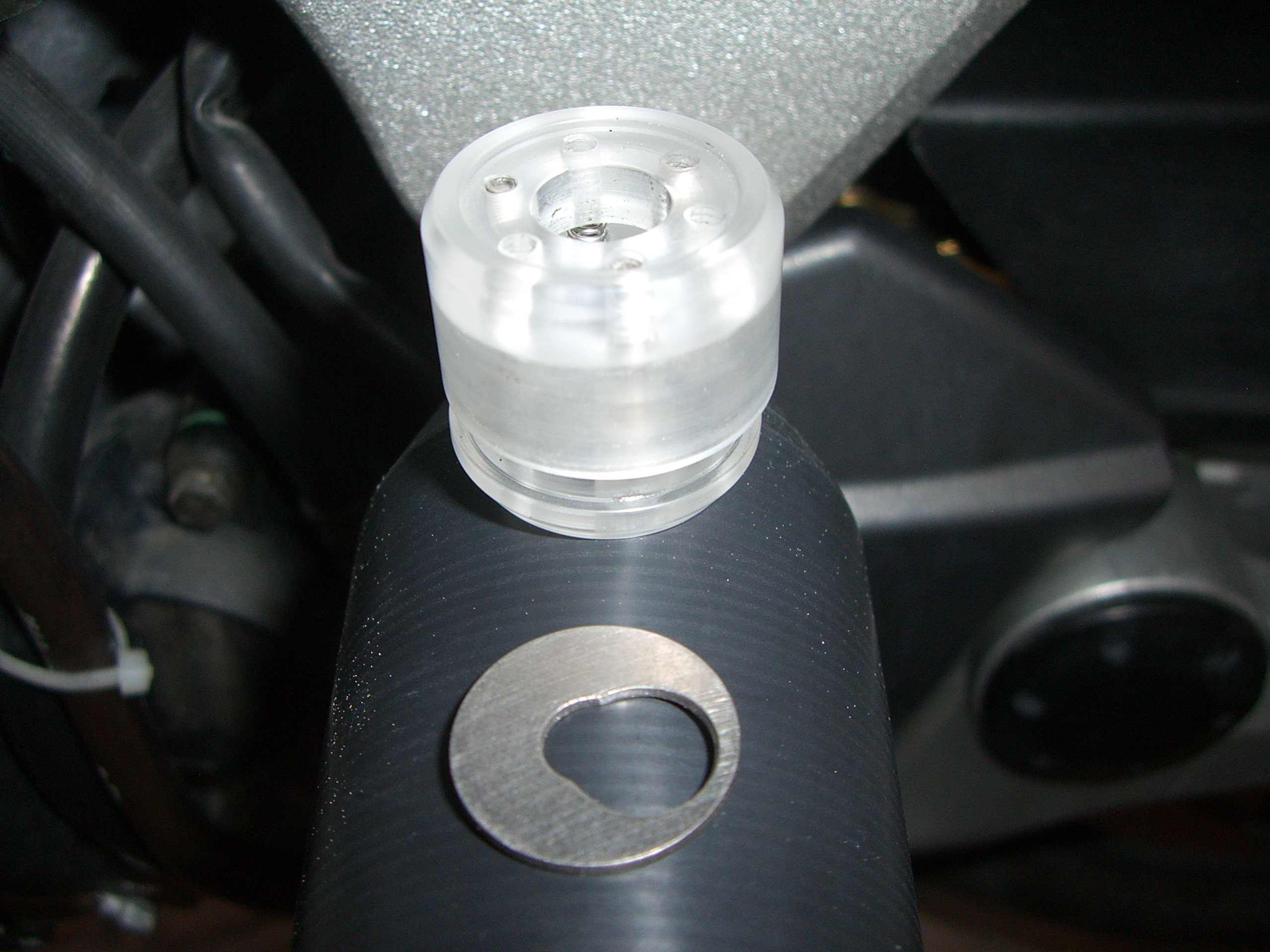
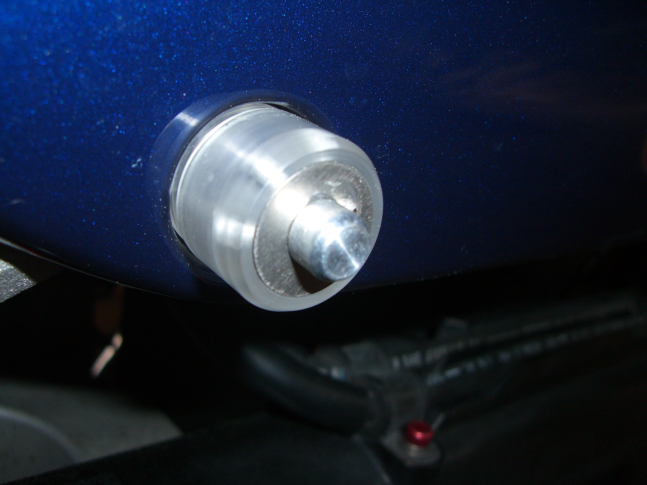
The next idea was to to replace the shouldered bolts, those three on either side. What I didn't like was that once the bolt was released that if the others were undone, that the fairing would drop. What I did was to spin a 6061 alu. .375 rod, tapped the back side, spun a slot near the other end, and chamfer the outside end. I then installed a bolt on the backside of the bracket that the screw would normally go into. I them installed the six aluminum rods with some 242 Loctite. The clear acrylic bobbins are two piece assemblies, three SS springs, and three 4/40 SS screws to captivate the assembly. This assembly slides over the rod. For fun I bought some titanium washers and machined an offset hole, it looks like a keyhole and acts like a lock. The bobbin itself has a counterbore, which captures the titanium washer. Assembly of the bobbin is simple, slide it on, push and slide the keyed washer until slips into the slot and release. The washer wont' go anywhere, the springs are internal, the screws can't unscrew, and the fairing is under a slight amount of spring pressure. It is very fast to take off, press, slide the keyed washer, and slide the assembly off. Sometimes I would not thread the original bolts in correctly, now the rods hold the fairing up and there is no more screwing around.
I also put two metal inserts in the bottom of the right(?) fairing so I don't have to worry about those crap plastic fasteners. The look is rather techie, and could be a love it or leave it. But for me, form follows function, and having them means a nicer time working on the cycle. I am working on the four bolts for the shroud at the bottom near the exhaust manifold. The prototypes are fine, just not there yet.

-
As the RPMs increase the voltage increases, ok. If you could go from a 3 to 2 to a single coil output, would you not be knocking down all of the extra current and load? My little idea would be a voltage sensing circuit which would disconnect the windings as the voltage increased. Since it looks as though you are using a individual diode circuit per each coil set, deactivating two at the top rpms might be a bit choppy, but might still could do the job. My thought is that with SCRs, what is the sense of a coil if all it is being done is throwing the current down the heat drain. A single coil should do the trick at top speed, at mid speeds two would work, and at greater loads and or lower rpms, all three. "On my orders, unleash hell".
-
I love titanium, but would for my project have used steel in the clamping area, stainless or a chromed stee. That being that under failure the ti bolt would fracture, and the steel would stretch. I wouldn't worry about the galling, based on my experience that disimiliar metals are more unlikely to do so. If you are going to apply any material to the threading section, torquing the titanium bolts might not be accurate. Most torque standards that I know of are dry states. Are you going to clear anodize and if you are going to color it, are you going for a UV stabilized color?
-
As for the bolts, could you have bought the stainless socket heads extra long and not fully threaded and then single point threaded them or used a die on a lathe? Basically cut off the non usable threads and cut new threads? Nice job on the clamps, now onto the 5th generation.

A New Angle On Clipons
in Modifications
Posted
Ultimate, I had the TC bright dipped anodized, and the second is going to be gloss black anodized. I did install the first for a fit check, and will have to remove a small amount of material where it rests above the steering column to get the lock to engage properly. It is beefy, and if I had the time, I would do the lower clamp also. As for the bars and the pic, it is shown to illustrate function, many others may see just a lump of aluminum. Gilles Tooling makes a nice adjustable set, but I wanted something a bit slicker. It is also adjustable front to back by way of the holes in the rectangular piece of aluminum and the forthcoming round piece which slides over the shock tube and mounts to the triple. I am using 7050 for most of it, and 6061 for the rest. Once you get the fit after so many miles, I see dropping some loctite 242 into the threads and even on the ball to ease the mind.