JAM
-
Posts
45 -
Joined
-
Last visited
JAM's Achievements
")


-
 JAM changed their profile photo
 -
Up in Bountiful. Good to know another VFR fan in Utah!
-
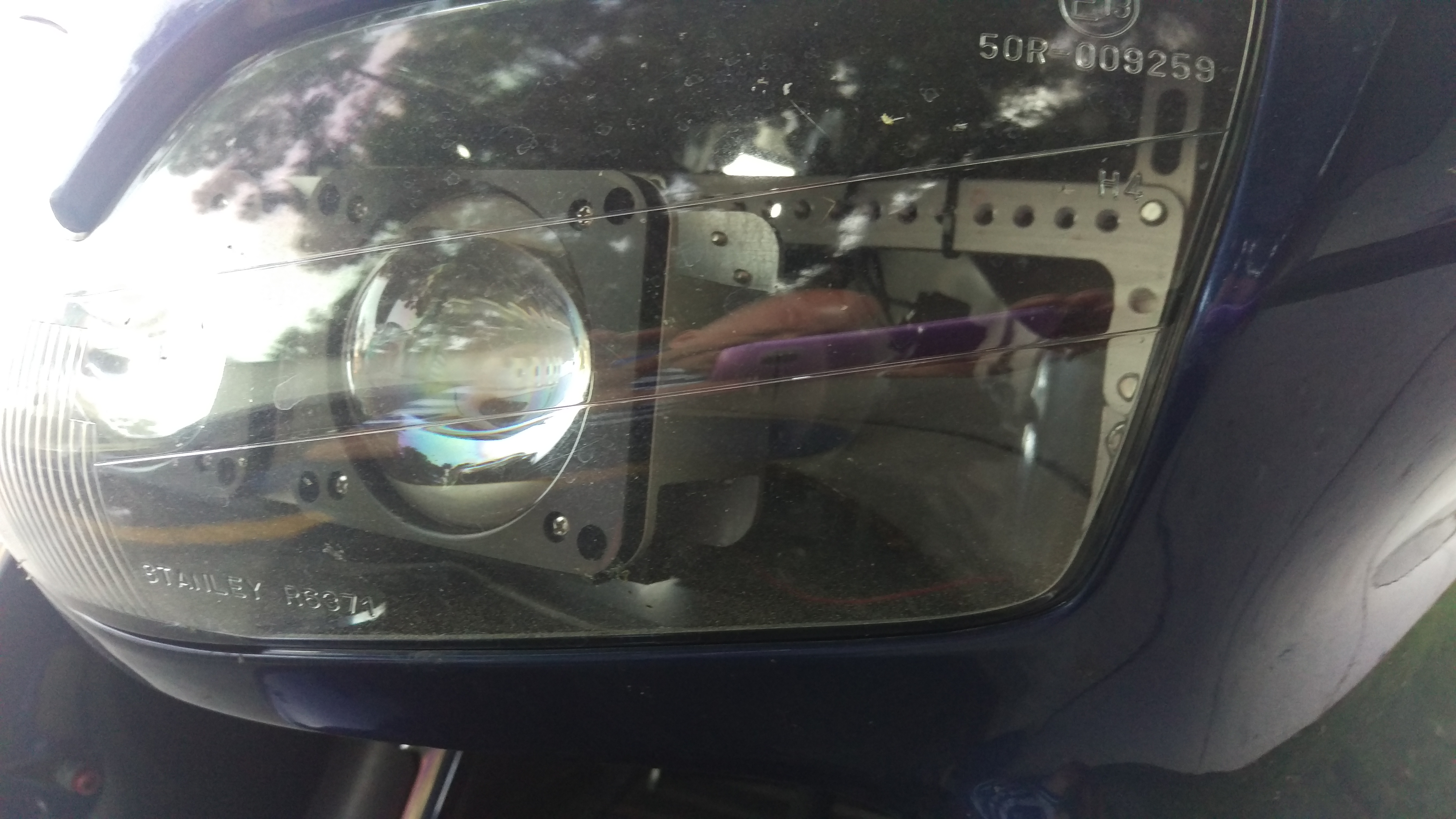
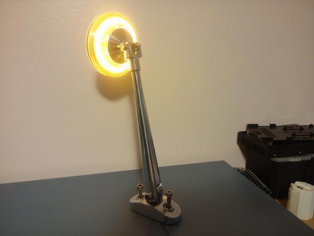
Based on the amount of light these are giving me, I could have gone for the smaller assemblies and their inherent losses. I ordered these off off of amazon knowing they would have to be broken down and re-engineered. 90% that are sold are made to be installed in a sealed headlight housing, affording it some protection from the elements. These use H1 bulbs, in which I machined the lens holder, spacer, and the sealed bulb holder. Unless you have your own machine shop, I would not recommend my method. My target was simple way to access and adjust the headlight. That need to move them precisely, hold them securely/protected, and have them function better than most anything on the road led me down this particular path.
-
I should have taken pics as I made it. This is the best shot I could get right now. The first pic shows the assembly and the modified projectors. I had to make new ones because the original ones were not watertight. The only things I saved were the reflector and the lenses. Bulb holder assembly up to the lens holders were made. Anodized alu. and black delrin. The two assemblies are married, and swing on a common anodized shaft. That shaft is clamped with a pinch clamp. that clamp mounts to the perforated bracketry behind the headlights. There is a small cover plate on the bottom fairing, I temporarily removed it, drilled a hold in the OEM headlight which aligns with that pinch bolt. Headlight adjustment is easy. I don't worry about alignment as everything is spot on. The lighting is simply amazing, just cannot be explained.

-
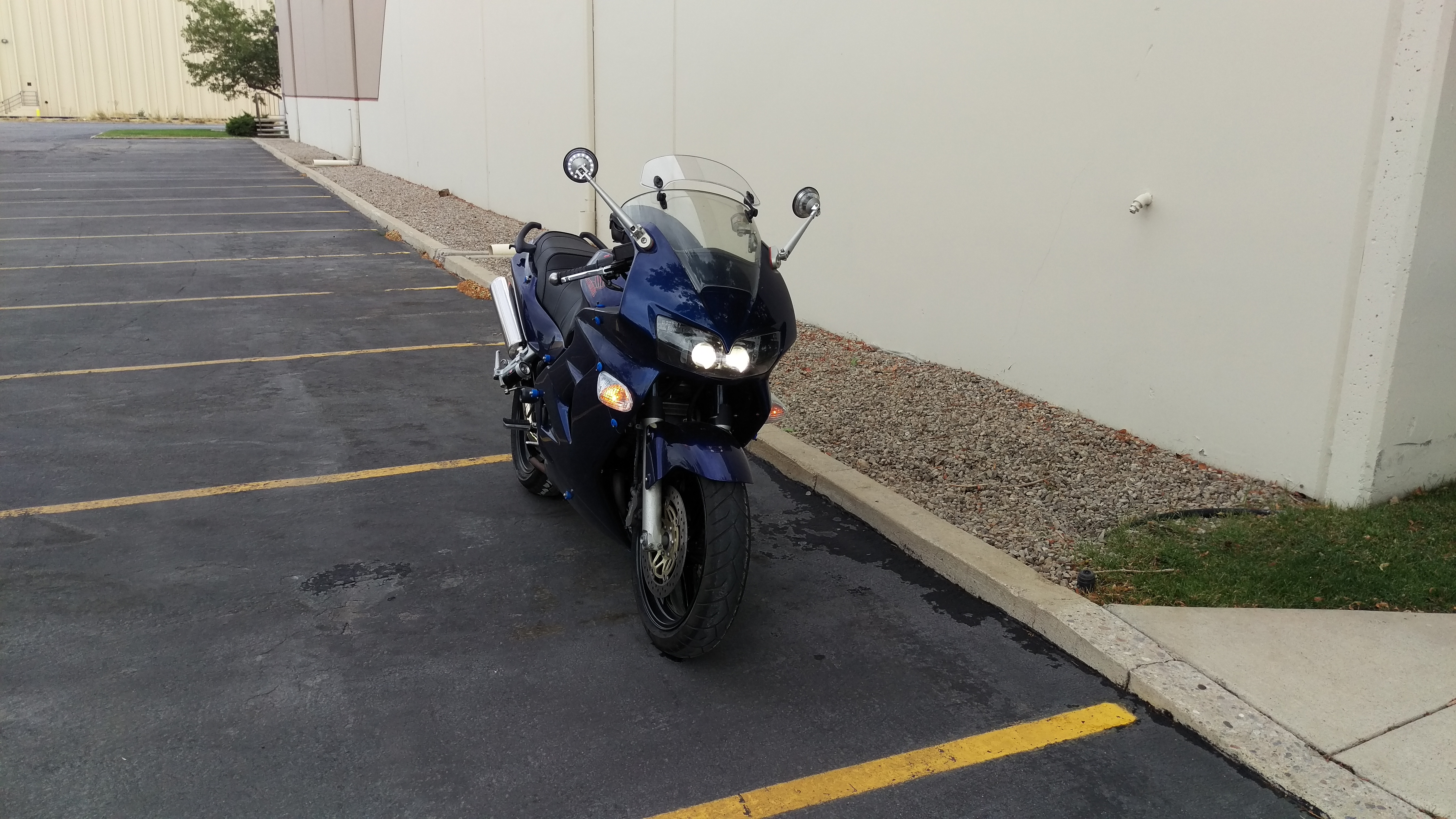
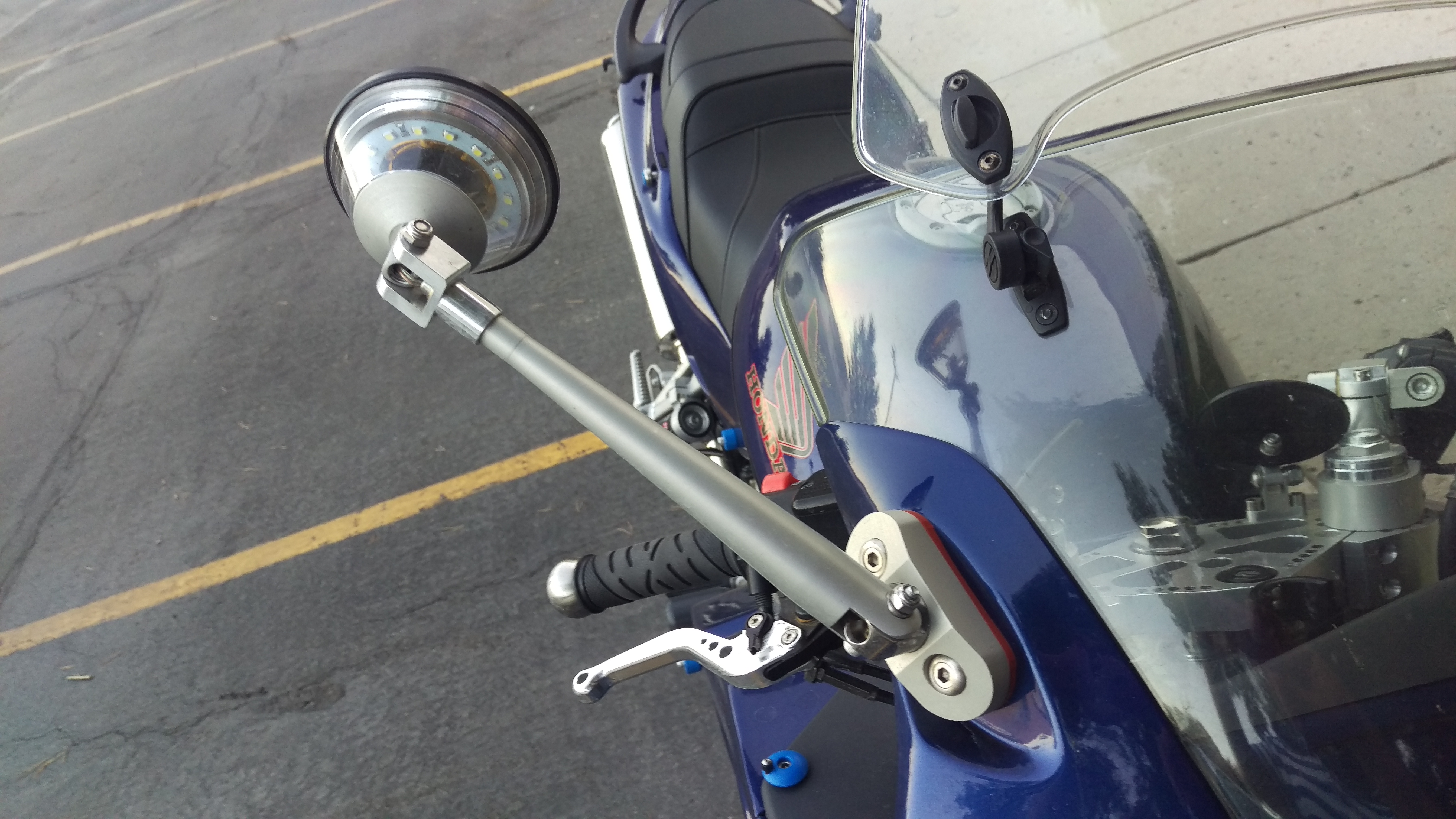
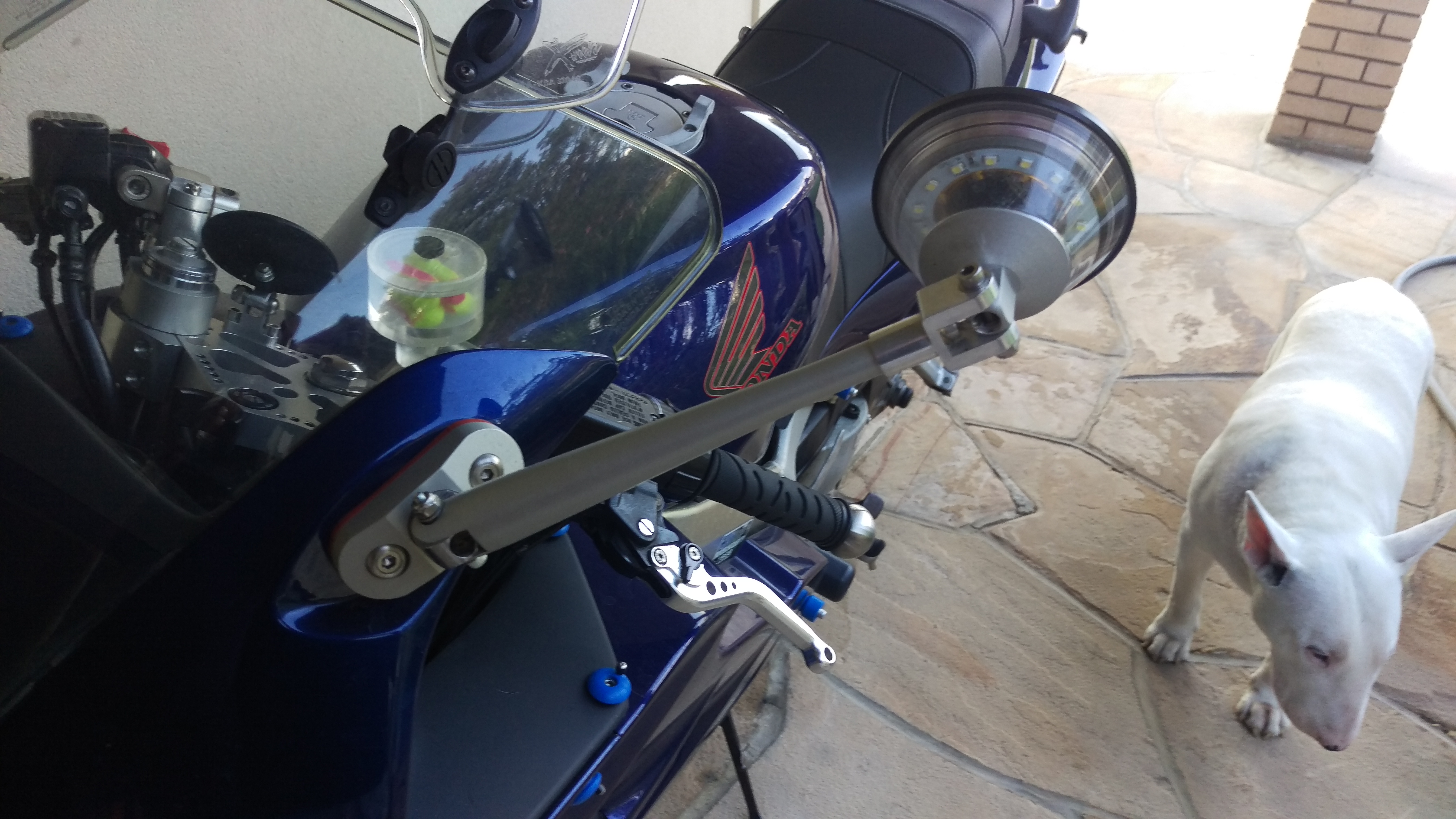
The bigger project. The only thing I did not make were the convex mirrors and the halo LEDs. Clear anodized alu., orange silicone spacer modified fasteners,hollowed tapered stalk, and fully adjustable swing points. White LED halos. Tolerances are tight, no water ingress, and most importantly, no vibrations at speed. I made the mirrors small, and positioned the pivot in the middle. I have had some mirror fold at higher speed, so this design at least eliminates that. I made them longer to avoid my shoulders getting in the way.
-
I machined new bar ends. The bars are solid 6061 T6 AL. black anodized.
-
When I get off the bike, I wanted a place to put the ear plugs. It can handle four plugs. It was cheap, aluminum and acrylic. The lid rotates with a off axis swing point. It is spring loaded and snaps shut. It does what it is supposed to do.
-
I had to cover the hole, Black delrin with some stainless hardware.
-
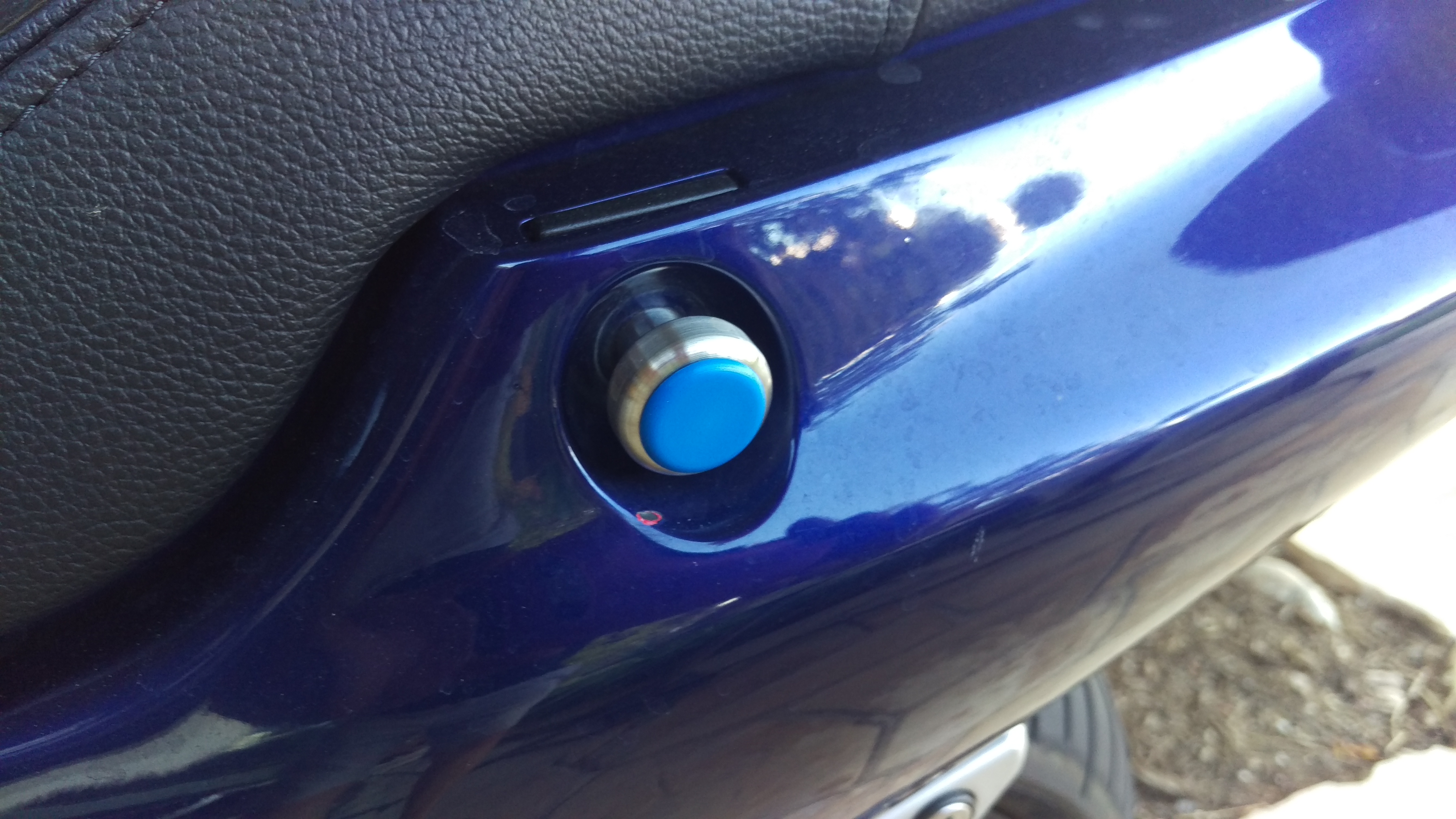
I changed the frankenbolt. Stainless with a blue delrin insert. What more can I say?
-
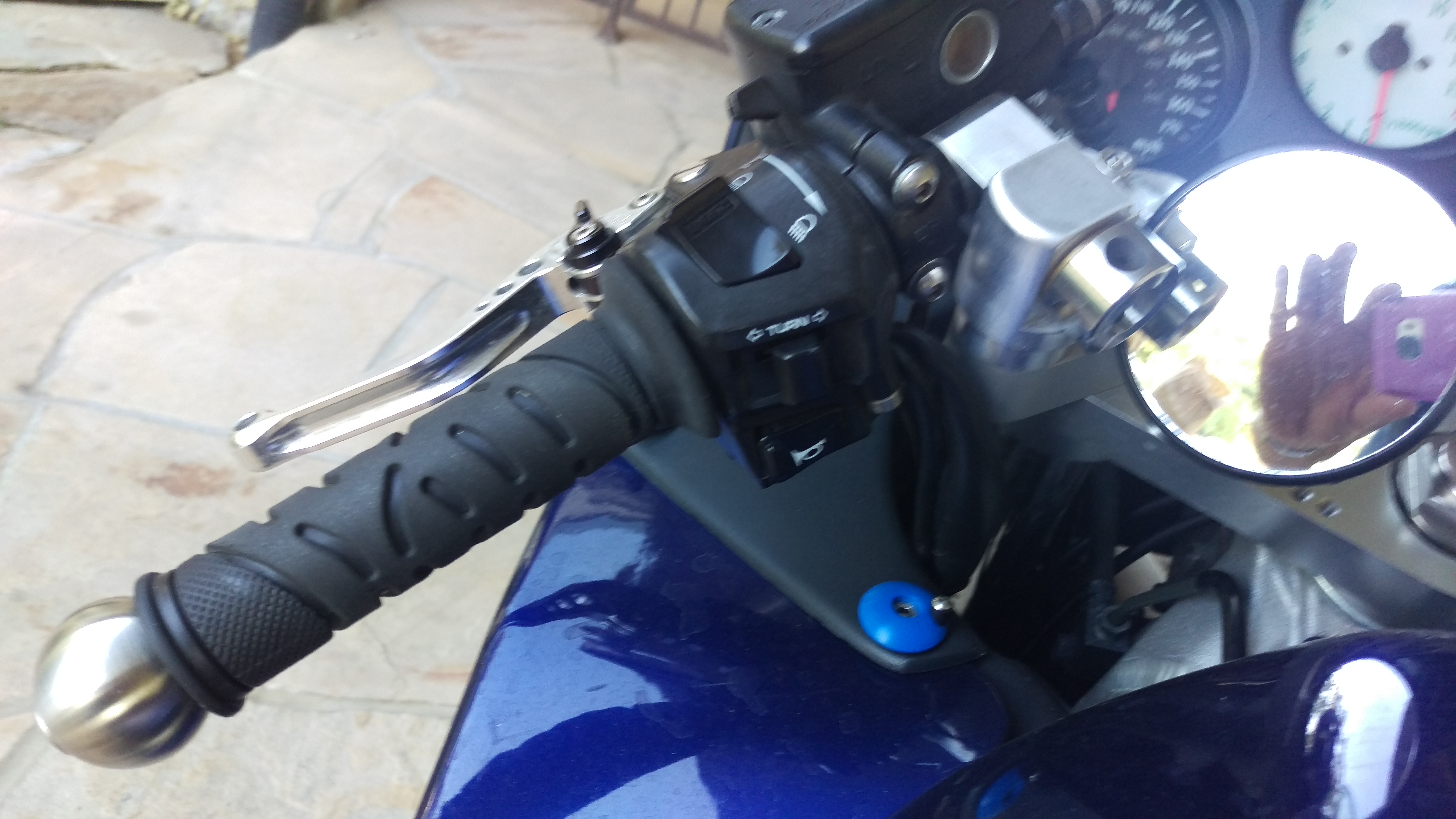
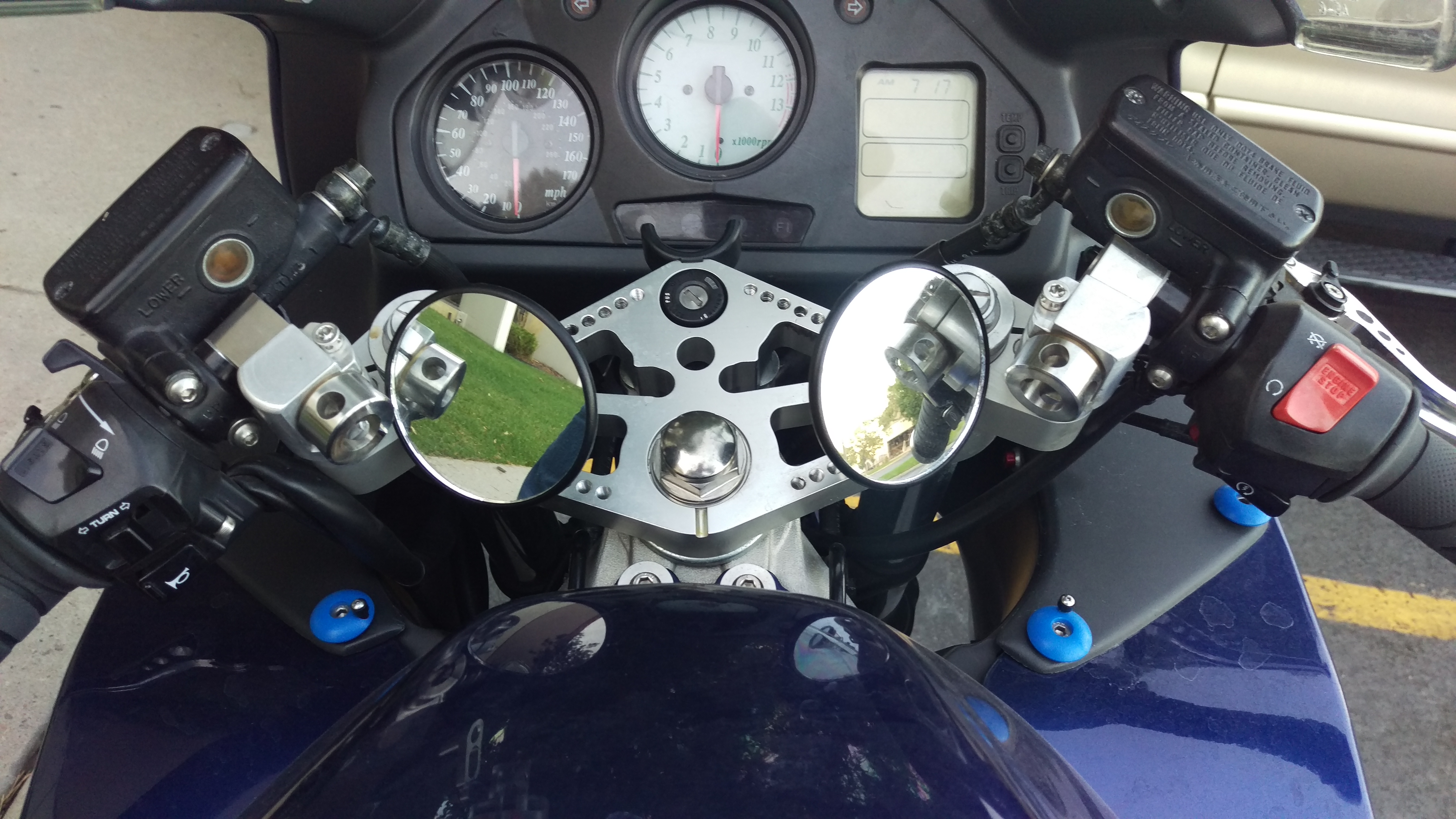
It gets a bit busy here. I bought a titanium yoke nut, just because. The mirrors are blind spot mirrors, they work, but getting used to them and working on tweaking the location. The triple clamps hopefully explain themselves. I can adjust the angle, clamping them down with the single pinch clamp and the the nuts with the holes in them, Conventional right hand screws on the left and reverse threads on the right. If the pinch bolt loosens, the thread direction tightens. I have another bar holder with microadjustments and a fail safe locking position. They are holding nicely, so no big rush. I machined the key holder at the top, It holds the weight of the keys and I don't like the keys marring the tripleclamp.
-
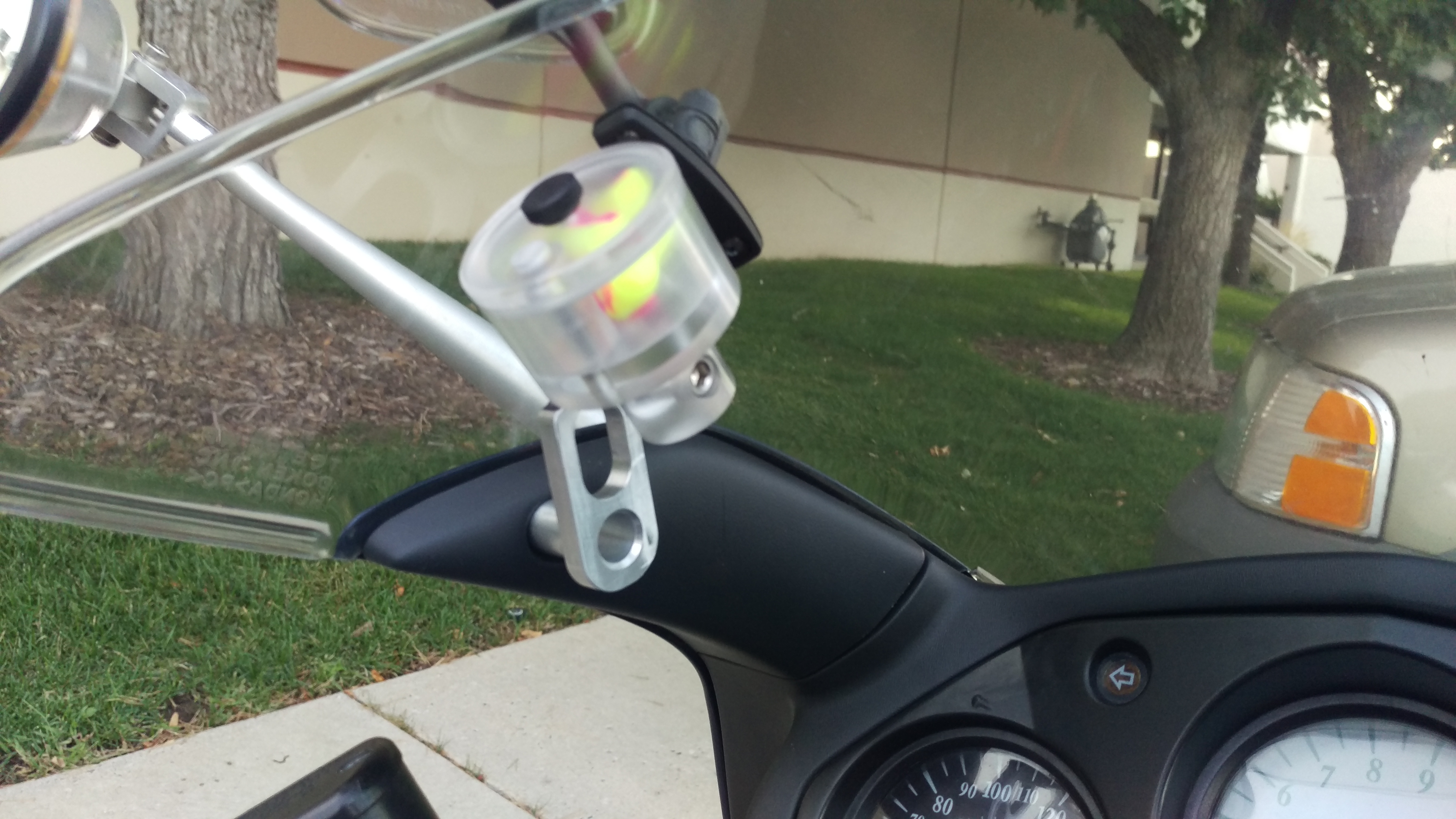
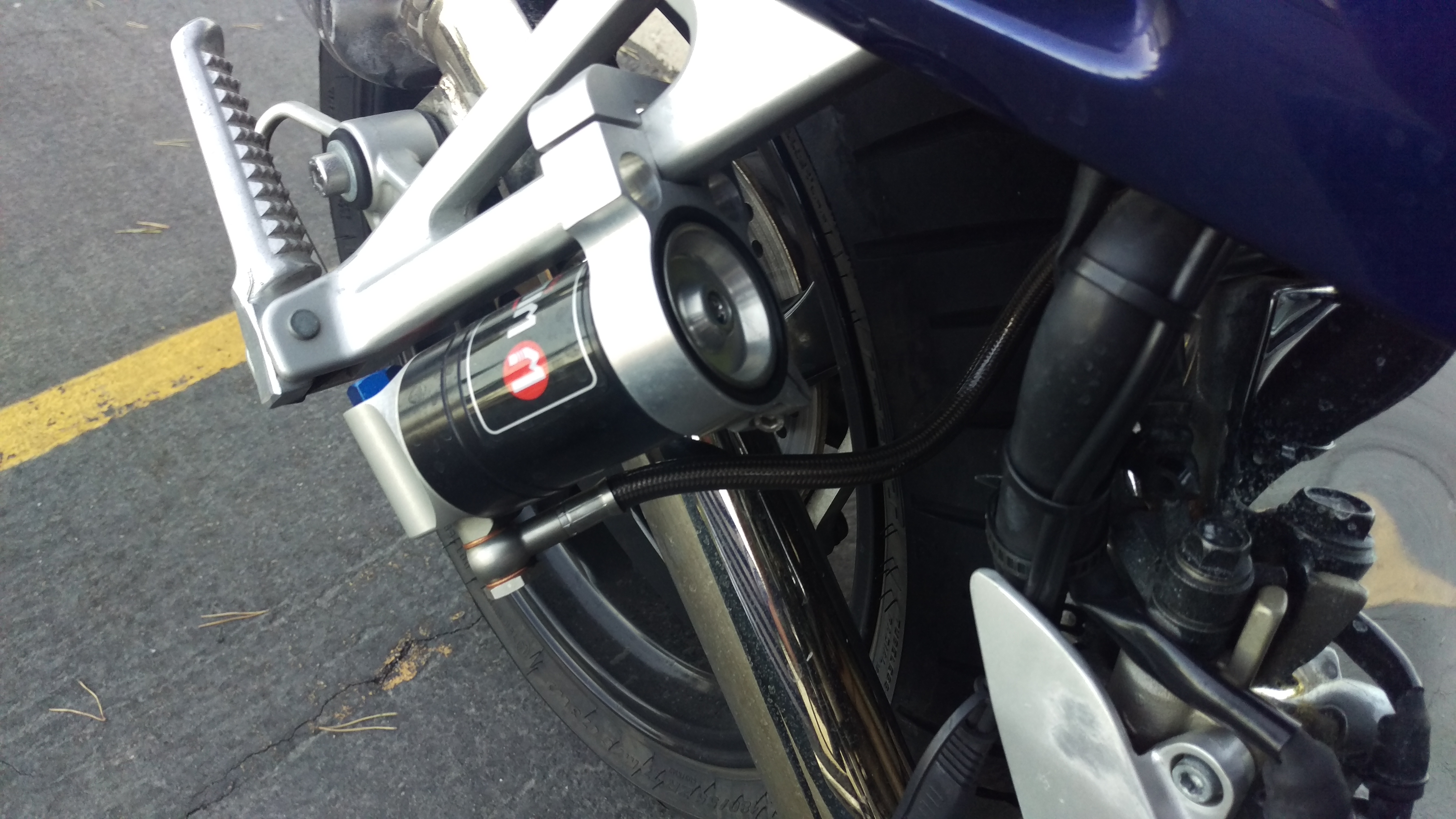
I thought I would just continue this thread and illustrate the changes. Sorry about the dirty bike, it gets used, I am just busy. Here is the WIlbers reservoir mount. Half of the aluminum parts are unanodized, I will be pulling the parts and finish them this winter. I clear anodize them, black fades in the sun.
-
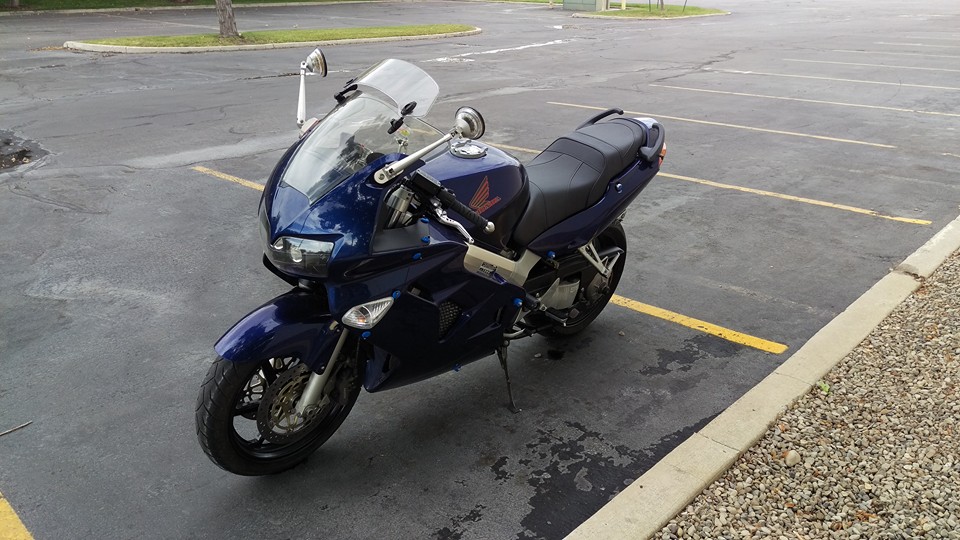
I did some machining and some tweaking. I ordered some HID bixenons/projectors off of amazon. I saved the reflectors, and re-machined entirely new housings. I cut the back off of the Honda headlight and mounted them on a custom bracketing system. I designed it so I could align the headlights with one screw from the bottom. I got lucky, it works as well as I hoped. The alignment is perfect, and still prefer my system over LEDs bulbs. I forgot to mention, the system is a projector system, the only way to go if you do HIDs. I bought a new seat cover off of Ebay in France, love it. I got a Wilbers 841 rear shock on a outrageous sale for 350 brand new. I machined a new bracket for the reservoir that attaches on the passenger peg bracket. Last year I added the deflector off windshield, it helps a little, not earth shattering a change. I machined some new mirrors with white halo leds. I made them longer, to go around my shoulders. They have adjust ability way beyond stock. They surprised me with no vibrations a driving speeds, crystal clear. They are small, convex mirrors, but do the job. I machined out set of triple clamps that are similar to Gilles model, but have more adjust-ability, more pics later if curious. A bunch of other smaller farkles. I still cannot believe just how fast this thing still is. Speeds which I never thought possible over sweepers, the rear shock is working well. This winter the front get some TLC. I sometimes think about changing, but then I ride it and realize every decision comes with sacrifices, both financially and mechanical.
-
I made them based on a couple of needs. First is my shoulders getting in the way, a little more visibility, and a bit more adjustability. It took a couple of Sundays and I have a bit more to do before I add them to the bike. But they work, and I am off to the next project next week. I need to get them them anodized and make the rubber spacer, but what else do you say about mirrors?
-
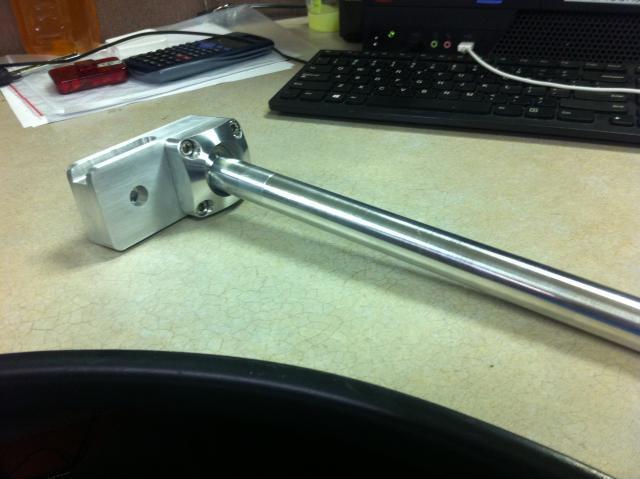
Ultimate, I had the TC bright dipped anodized, and the second is going to be gloss black anodized. I did install the first for a fit check, and will have to remove a small amount of material where it rests above the steering column to get the lock to engage properly. It is beefy, and if I had the time, I would do the lower clamp also. As for the bars and the pic, it is shown to illustrate function, many others may see just a lump of aluminum. Gilles Tooling makes a nice adjustable set, but I wanted something a bit slicker. It is also adjustable front to back by way of the holes in the rectangular piece of aluminum and the forthcoming round piece which slides over the shock tube and mounts to the triple. I am using 7050 for most of it, and 6061 for the rest. Once you get the fit after so many miles, I see dropping some loctite 242 into the threads and even on the ball to ease the mind.
-
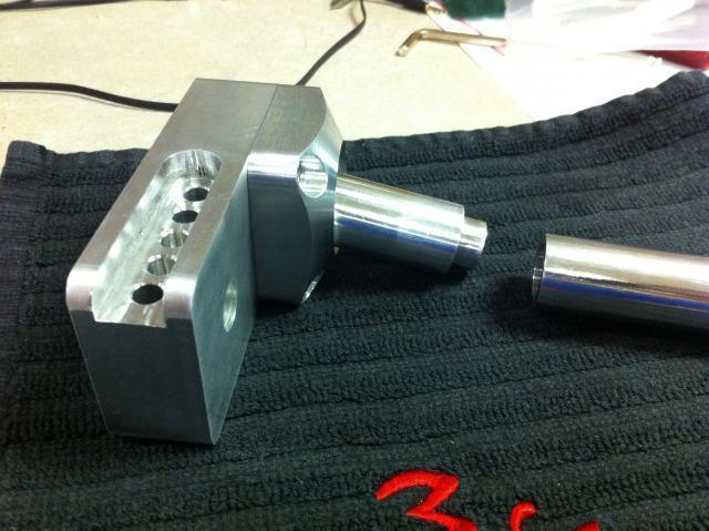
I have had a need for a while now regarding the positioning of my hands on the bars. I wanted a more fluid way of fine tuning where the bars should set. Here is the right side, unanodized, and partially tested for strength. They may look like they would move, they won't. The ball and socket have been cnc machined, and some more pocketing is coming down the line. The bars are solid, and I am even going to redesign the grips in an oblong cross section to eliminate the numbness my hand goes thru sometimes. It is weird I know, but new is that way sometimes. It will intergrate it into the triple clamp I posted earlier.
-
Thanks for the critiques. Here are the reasons why it is flat on top. I machine that side first, top, holes, counter-bores, and tapped holes. Next comes the profile and pockets on the other side. I use a end mill with a radiused corner, so as to not add stress risers on the longer shock clamps. The clamps use stainless pins with two M6 threaded holes each. I was trying to avoid galavanic corrosion, and like that screws can deflect, but shouldn't because of the tight fit. I have a backup, but have not slit the clamps or counterbored it. My first is off to the anodizer, and if you want it, PM me.