
luigi
-
Posts
323 -
Joined
-
Last visited
Content Type
Forums
Profiles
Gallery
Blogs
Downloads
Events
Everything posted by luigi
-
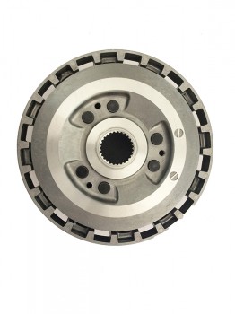
From the album: GSX 750 F
-
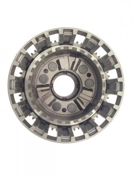
From the album: GSX 750 F
-
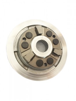
From the album: GSX 750 F
-
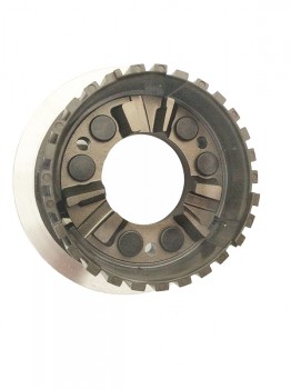
From the album: GSX 750 F
-
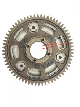
From the album: My Track VFR
-
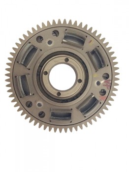
From the album: My Track VFR
-
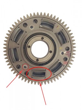
From the album: My Track VFR
-
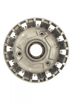
From the album: My Track VFR
-
From the album: My Track VFR
-
From the album: My Track VFR
-
From the album: My Track VFR
-
From the album: My Track VFR
-
From the album: My Track VFR
-
From the album: My Track VFR
-
From the album: My Track VFR
-
From the album: My Track VFR
-
From the album: My Track VFR
-
From the album: My Track VFR
-
From the album: My Track VFR
-
From the album: My Track VFR
-
Hi. Yes, the water leakage is the great doubt abou this work, but i'm confident in the welders experience. I have no idea about dimension and shape of the TL1000R, but could be interesting some pics! Thank you slowbird i'will keep you all update. Ciao, Luigi.
-
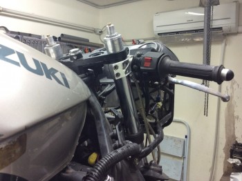
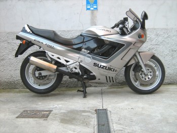
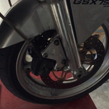
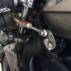
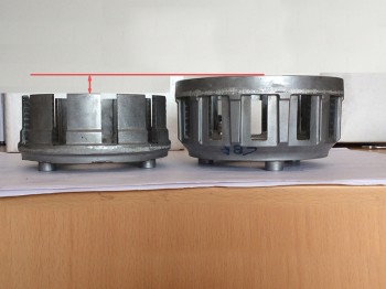
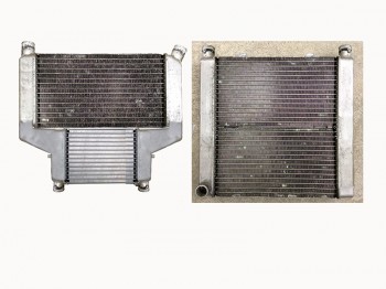
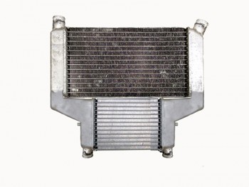
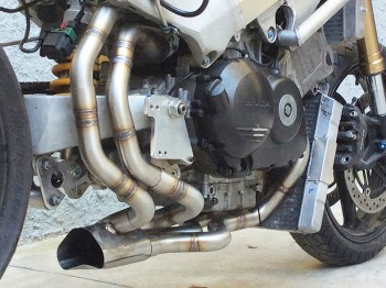
Hi to all. I know, it's an old never ending story about this project but, since i never lost the hope to finish it, i restart the work to have a 5th gen VFR to use for track days. So i would like to show you the latest modifications on the exhaust system, the front fork and the cooling system. As you can see i've installed the two complete fork legs coming from a 2008 Suzuki GSX-R 600 (i know that in US there's many VFR that uses the VTR SP fork, but in Italy this kind of suspension are not so easy to find used and the price are anyway expensive.) The clamp are designed by me and are manufactured on CNC. The clamp offset are reduced to 30 mm from the stock measure that is 37mm. This is the exhaust system routing. The pipes are finished but the compensation chamber are still incomplete. Below, on the right, the main cooler, made by the union of the two stock elements and mounted in front position to have more cooling effect. Above, always on right the additional cooler, made by the union of two scooter Honda coolers. As you can see, this cooling system solution shows a problem, the main cooler low edges surely go to scratch at the first lean angle, so i studied another solution that show you later. I've choosed to remove the oil cooler, instead i've installed the intercooler used on the CBR 900 (i don't remember the year, it seems the 93 but i can fail) To have more cooling effect, since the water have the additional charge to cool down the oil too, i tought to mount a supplementary water cooler in the same place where the oil cooler was placed. This is a schematic compensation chamber description. This i the solution that i found to have all four pipes with same lenght and have one junction point. I respected the stock pipe leght (around 670 mm). The view point of this drawing is the "front wheel" point of view seeing to rear of the bike. This is the main cooler, obtained by the union from the two stock coolers, here are just positioned... ..and here the final result once completed. This in theory why, as you seen this cooler is too height, so i tought an alternative solution that is ...this. This is just an example, created with Photoshop. The final cooler anyway will be very similar. Conceptually i will use one stock cooler and one that is again the Honda scooter part, united with alluminium sheet formed. Once created and mounted i will post pictures. This is the sequence followed to obtain the supplementary water cooler. Two scooter Honda coolers with removed all fixing points, hose joints and the two central "shoulders". The final step. Red line shows the welding to unite it. After, in the low side, cooler was be holed to apply the joints for the hoses to connect it to main cooler. That's all, for the moment. Ciao, Luigi.
-
From the album: My Track VFR
-
From the album: My Track VFR
-
From the album: My Track VFR