


cassandtim
-
Posts
111 -
Joined
-
Last visited
Content Type
Forums
Profiles
Gallery
Blogs
Downloads
Events
Posts posted by cassandtim
-
-
I just measured and modelled a set of bases for Magellan before I set off for the Summit Meet. Definitely a P.I.T.A. as the arm's base shape doesn't use what I'd call "normal" geometry. The arcs on the base are spiral curves (constantly changing radius).
I think Magellan will be sending off the .DXF files to his CNC machinist this week to get a set knocked out. Hopefully we can nail the design (correct angles and such) on the first try.
Cheers,
-T
-
Great to hear that you are still attending the Summit. Can't wait to meet the man that created the RCBVFR and will create the RCBVFR Version 2.0.
Cheers,
-T
-
Super glad to hear you're ok! Most people haven't had the luck of walking away from a 75 mph crash on the road. Too much stuff usually gets in the way!
As for the bike: if anybody can fix it, you can.
As for the Summit Meet: I can totally understand why you wouldn't attend but I sure hope you do!
Take care,
-T
-
Just seat time!
I totally agree with this. As someone that has been down a couple of times and have witnessed a few bike accidents; the number one thing is to get back on and ride as much as possible. Sometimes it can take a whole season or more to get back into the swing but take it easy, ride well within your comfort/safety margins and put those miles on!
-
I don't think that WSP is going to agree with your removal of your front signals!
-
I was fully prepared to deal with a bunch of dealer malarky after my blue connector caught on fire on the way to the Canada Meet this summer. I was stranded in the mountains outside Yakima, had to get a tow into town (thank God for AAA) after a 4 hour wait, cooled my heels at a Holiday Inn Express for the evening, and finally fixed the issue the next morning with hardware from ACE Hardware Store and continued on to the meet.
I was told the same thing by my dealer when I enquired about making the trip knowing that I could end up stranded and having to fix the issue myself prior to the recall work being done. They said that Honda Techline would debit their warranty claim if the harness was found to be tampered with. I, personally, find it pretty hard to believe that Honda has hired a lackey to sit in some back room and tear apart every harness that comes in to see if it has been altered. I'm sure that the expense of this recall has been great enough. I was, however, very careful to solder the wires back in place and make it look as though I hadn't repaired a thing. I had the recall work done about two weeks ago and with a little additional wiring work to the new harness everything is fine.
If they had caught on I would have read them the riot-act and immediately contacted someone at the NTSB. It is, after-all, a NTSB SAFETY Recall. If I were you I would remind your dealer of that and ask them how they will respond to your attorney and any appropriate consumer protection agencies should something drastic happen to you and the motorcycle upon failure of Honda's junk wiring and them not pursuing the recall on your behalf.
I would be polite and professional but incredibly unrelenting in the pursuit of what is due you. Accept no other answer except "we'll take care of it for you".
Rant off,
-T
-
Wow!!!!
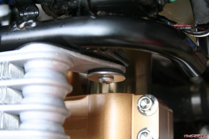
Magellan and I just finished adjusting the shock reservoir bracket (the 1/8" aluminum plate that the CNC'd mount clamps to). What an incredible P.I.T.A.!!!!!!
We had a friend (big fella) sit on the bike to see how close the bottom of the reservoir was to the brake lines/chain guard. Way to close for comfort even though the shock has an 1100 lb (19.64 kg) spring. We quickly realized why Elka wanted to mount that thing on the passenger footrest bracket. They obviously didn't want to let us have 1 extra inch of hose length though :goofy: .
I'd be more than happy to converse with anyone wanting to do this mount; even give you the CAD file to get it machined. I'm not so sure that I want to go through trying to mass produce them though. Not to say that this build hasn't been rewarding but, as most of you that fabricate stuff for your bikes know, it's been extremely frustrating at times too.
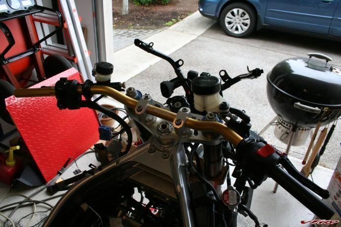
So, onto the bars issue. I knew that I wanted to go with a taller and wider bar set-up after spending some time in the twisties with my wife's 2002 BMW R1100s. I could carry more speed through the corners on her bike than the VFR (10 mph or so, that's quite a difference). I knew that a lot of it had to do with better suspension but felt that some of it had to do with a more upright riding position. I'm not sure if any of my ideas on it are valid or fool proof, I just feel that it has more than a little bit to do with it. Another upside is that my upper back won't be killing me after a few 300-400 mile days :beer: . They are definitely wide though (more leverage = less effort to counter steer). I put the taller riser blocks (17mm vs. 7mm) in today and it even feels better. At first I worried that it would detract from the look but after checking it out from all angles I think it looks pretty sharp. It's kinda like that CD that you may have bought for one song but eventually you love the whole thing because it grew on you.
I'll let you know about the change from stock bar postion after I see a few 6th Gens at the "Kootenay Hootenanny" later this week. I'm hoping some attendees will want to take the bike for a spin and give me some feedback.
And lastly, I'll leave you with some food for thought: I used to ride with a friend that had a scary fast 'Busa. He is/was a damned fine rider (fastest & smoothest I've known). He eventually got himself an R1 and was able to eek a little more speed out because of the weight decrease. He finally ended up on a custom 650 motard and when he rode that bike it seemed like he was twice as fast than he ever was on any race replica. I'll concede that his technique was superb no matter what bike he rode but even he said that it had a lot to do with being more upright. Maybe something, maybe not.
.......and no, I'm not going to paint the fender. Mostly because I love to be annoying
 .
. -
After Much toil this past week we finally have lift off............
Stoked does not begin to describe my feelings right now. Almost a year to the day (August 25th, 2007) after Ol' Red and I suffered a mishap because of a cager's inattentiveness she is back on the road and better......Oh sooooooo much better..than before.
Here's a couple of hard working mugs..... Magellan & Tim:
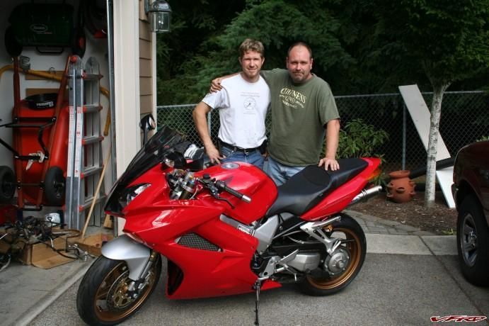
Loni & Tim next to Ol' Red
I took the bike for a very short shakedown ride late this afternoon. Still has that awesome VFR turn-in. The suspension can only be described as very authoritative. It eats up the bumps but seems firm at the same time. It definitely feels planted. I'm going to check sag on Tuesday.
The bike tracks very well. No wierdness at all. I locked the Throttlemeister on at about 45 mph for about a mile or so and easily road the bike no handed (in a straight line). It tracked very nicely.
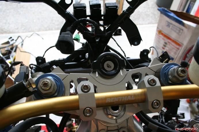
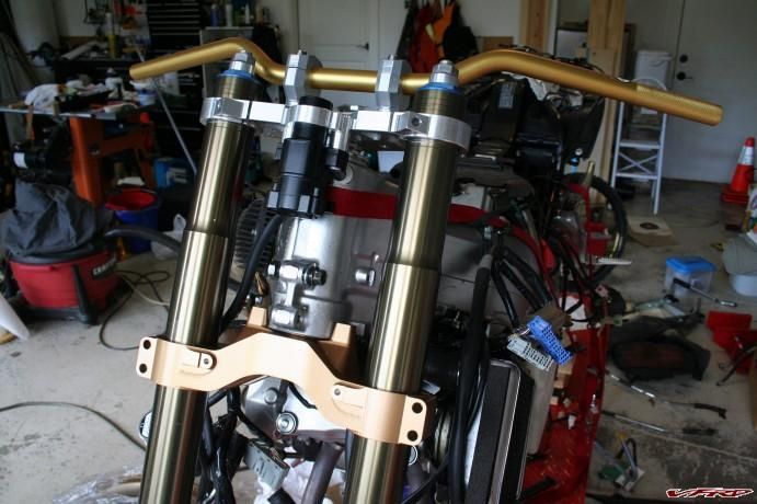
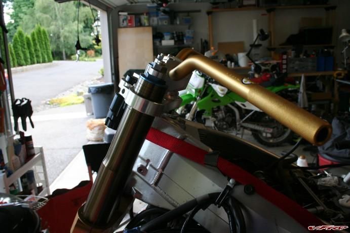
The completed front end:
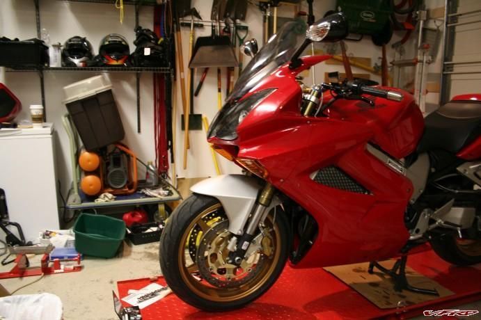
New Front End Complete, WOOT!!!
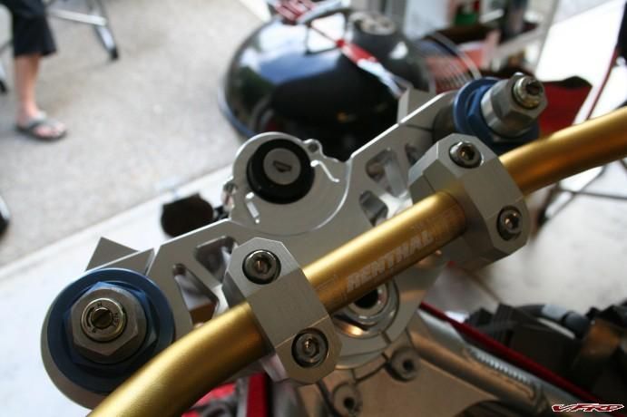
Upper view:
Upper View
Side view:
Side View
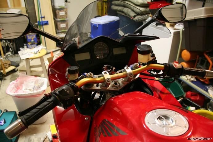
Final cockpit view:
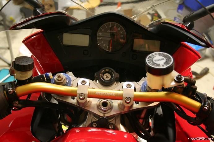
Final Cockpit View
A peek under the fairing:
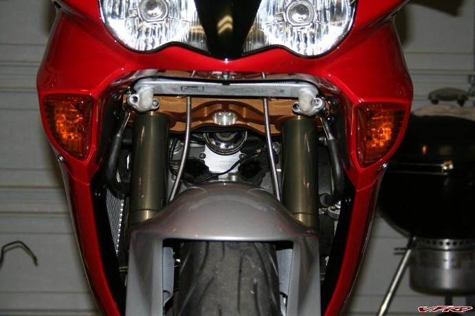
What's under the Fairing?
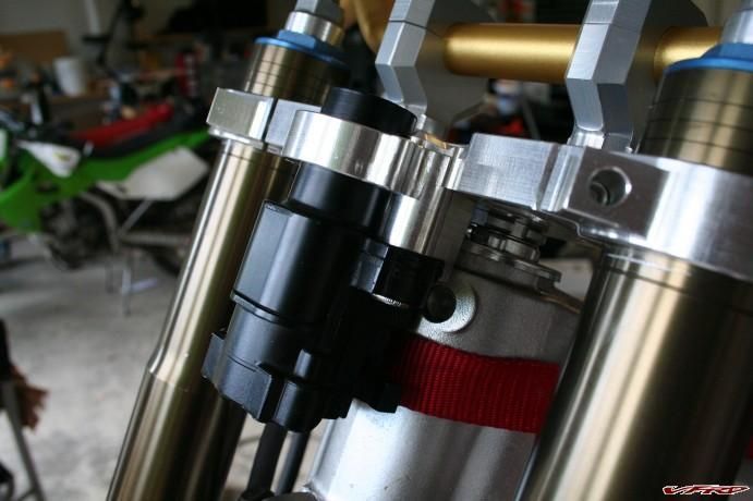
The shock reservoir clamp finally mounted:
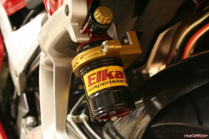
Reservoir Clamp Mounted!
I really want to thank all of the people in this VFRD community for the inspiration to even undertake this project. Without the forum I may have given up riding after the accident or at the very least gave up on Ol' Red and replaced her with another bike.
Some people that helped along the way (not in any particular order): Busy Little Shop, veefer800canuck, Kanadian Ken, silver#788, Opus, and many more that I'm forgetting.
A massive THANK YOU to Magellan for doing the majority of the reassembly work and getting the bike running (I owe you much my friend :wheel:) and to Darth Bling for the vast farkle knowledge (is it called "Farkle Fu"?), parts, tire mounting, and just hangin' out at the garage.
Now off to Canada for the PNWVFRD "Kootenay Hootenanny". WOOT!!!!!!!!
-
 1
1
-
-
Seb,
Those bolts are titanium from Yoyodyne. They're worth more than the oil cooler :fing02: .
They're only interfering about a millimeter. Magellan was concerned way more than me, and only from a form vs. function standpoint.
I'm soooooooo stoked to have this thing almost wrapped up. Keep your fingers crossed for me on the wiring recall. I'm hoping it can be done sometime this week.
-
The only Coordinate Measuring Machine that I used were Starrett metric rules and a digital caliper. That's "close enough for the girls we go with", as they say in the vernacular.
I finally got the front end somewhat assembled:
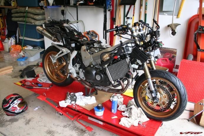
Bling-o-licious
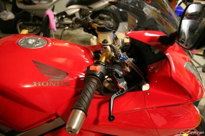
Another view from the cockpit with controls mounted:
Controls are mounted
I had to adjust the mounting for the oil cooler as the lower triple was hitting the stock mounting hardware:
Alternate oil cooler mounting
The lower triple, ever-so-slightly, hits the oil cooler at full lock. I suppose I could add a piece of tape or two to the back side of the steering stops but I figure there's not enough interference to worry about.
Left Side:
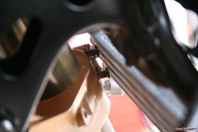
Minor interference left side
Right Side:
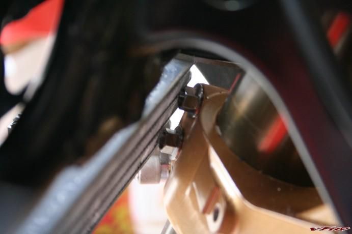
Minor interference right side
Another view from the top:
We have controls!
I had a minor revelation while mounting the controls on the bars. Since the bars are wider than stock, I'll need new throttle cables. I had a minor "Oh S__t" moment with this until Darth Bling informed me that longer throttle cables were available through the Convertibar company.
I'll be taking the bike into my dealer on Monday morning to see about getting the wiring recall done.
NOTE: A great & many thanks to my friends Magellan and Darth Bling for all of their assistance with this project. Without their combined knowledge and helping hands I would never have undertook this "little" project.
-
The bars are Renthal 758-01 Road Ultra Lows. Renthal says the width is 755mm, height is 100mm, rise is 60mm, and sweep is 95mm. Darth Bling recently purchased a set of LSL bars from Spiegler and they are considerably different (but just as nice) from the Renthals. I think that LSL offers a better variety for road options than Renthal.
Foto,
Truth be told, your post on the superbike bars was a major inspiration for the project :fing02:.
Cheers,
-T
-
Spinalator,
Your best bet is networking and trying to find somebody that does CNC machining as either a hobby or low-volume manufacturing. Most large-volume production facilities aren't going to want to set up to do a "one off" piece. The best piece of advice that I can give you is talk with your friends, mechanic, etc. and visit some hardware (nuts/bolts supply) stores and ask if anyone knows a good machinist.
The material certainly could be provided by your machinist but you could choose to call around and get the best price. We built these out of 7075 T6 aluminum and because of that the material was more expensive and harder to obtain than 6061 aluminum.
JZH,
Actually my scale read 39.6294275 mm :biggrin: That was after knocking several back.
I'm speculating that 40mm is the magic number because it comes out as 94.98 mm of trail and that's somewhat close to matching the Honda OEM manuals spec for 95 mm of trail :fing02: .
I've decided to space the bottom race with another snap ring as opposed to grinding material off of the lower to gain clearance. The next step is to get my OEM parts in and start building the bike back up.
Getting closer! I still might make it to the Kootenay Hootenanny on August. WOOT!!!
Cheers,
-T
-
I'll be releasing the CAD files as soon as I make some needed adjustments including the minor interference shown in the photos. I'll also be raising up the portion of the lower triple where the bearing and seal rest so that anyone else that goes this route doesn't need to use snap rings as spacers. :fing02:
-
Got the triples back from being anodized & powder coated. I'm very pleased with how they turned out.
I also installed the bearing races in the frame and pressed on the lower bearing on the stem. Having done that I decided to see if the thing actually fit and if my measurements worked out.
Here's a few photos:
First fit. Looking good so far -
Custom triples first fit
A view from the cockpit -
Custom triples - Cockpit View
The only snag I hit was the lower rubs on the frame a bit even after using the snap ring spacers. The good news is that I only have to remove about a millimeter to get it to work fine and the steering stop locations are perfect. I do hate to grind away that powder coat but at least it's in a non-visible area -
Custom triples - A little tight
The ingintion lock works perfect as well. WOOT! This was one where I was keeping my fingers crossed -
Custom triples - Ignition lock works!
Lastly, a side view. I'm slightly bummed that a set of nifty anodized preload adjuster knobs won't fit with the shorter bar rise spacers but I guess I can live with the sacrifice -
Custom triples - Side view
That's all for now. I've got to get the bars to the machinist tomorrow to open them up to 16mm diameter so a set of Throttlemeister bar ends will fit.
-
I exported the models as .DXF files and then the machinist imported it into his Delcam software. He used a program called Power Shape to do most of the tool pathing. That's about all I know about the process.
I will make the files available as soon as I get everything bolted into place and make sure that there's no changes that I have to make. I may ask Miguel if he can make them available through the forum.
Meanwhile, I also modelled up a reservoir clamp for my Elka shock because I'm not too fond of the hose clamp mounting.
The machinist surprised me with some killer handywork on the clamp face. Needless to say I was incredibly stoked to see the finished product. He's a super talented guy and has his own website at http://www.lonerindustries.com
The clamp:
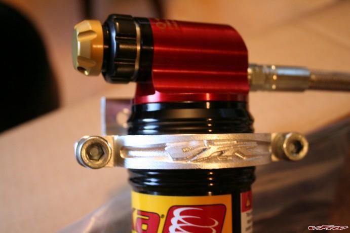
Reservoir Clamp1.jpg
Close up of logo:
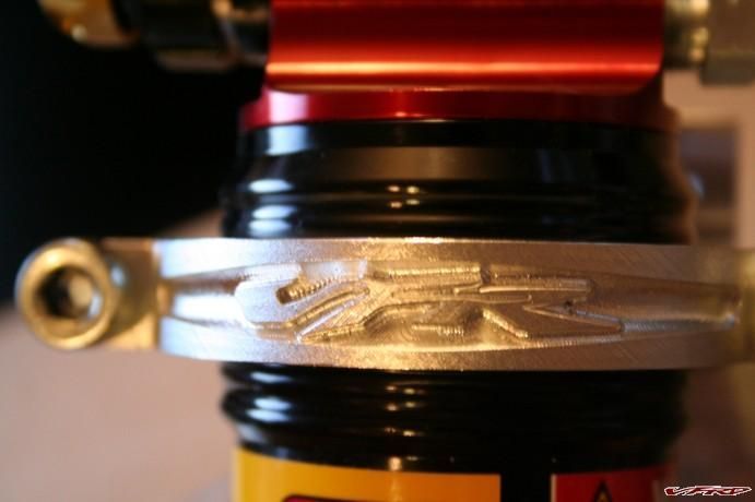
Reservoir Clamp2.jpg
Now to get this gem off to the anodizer. What color? The fastest color of course.......RED!!!!
-
40mm from center of steering stem to center of fork tubes.
Stock VFR offset = 40mm
RC51 (SP1) = 30mm
This offset difference was one of the deciding factors in having this clamp set made because the overall effect on trail in doing the conversion.
-
Nope, not Mechanical Desktop. I work in the civil engineering trades and own a licensed copy of Civil3D/Land Development Desktop from Autodesk. It just so happens that it runs on the plain-jane AutoCAD engine and you have the option to open it up as regular ol' AutoCAD 2009.
BTW, I knew nothing about 3D modelling in AutoCAD prior to modelling the mirror mounts for Darth Bling and then this project. Cool stuff though. It's nice to know that you can make all those parts you really want that nobody else (parts manufacturers) is bothering to offer.
-
Stem questions - so did you make a stem from steel alloy or is it Honda part? What is the oven/freezer trick?
(I can make a guess, but it doesnt hurt to ask.)
I used the stock RC51 (SP1) steering stem. I do intend on modelling the stem as I would like to have one machined that uses the internal thread style top bolt similar to the Aprillia and Ducati stems.
Because the stem and lower clamp use a force fit (0.002") I put the clamp in the oven at 300º for 35 mins and the stem in the freezer overnight. I put a little marvels mystery oil on the stem as well per Larry's advice and they went together with a tap from a dead-blow hammer and hardwood dowel.
You're welcome Tim... the clamps look the biz... 40mm offset is very important because it preserves the VFRquick handling rate whereas the stock RC51 offset doesn't... the only the thought that comes to mind is to
gull the top clamp like the bottom in order preserver the VFR's front end height and in addition there might
be enough room to hang a clip on...
If you weight them post the number so I may advise prospective customers...
Because I'm going the "Superbike Bar" style setup there's no need for clip-ons. I did do the measurements on fork length differences and it came out (measured from center of axle to top of fork):
Stock = 772mm
RC51 (SP1) = 759mm
Stock fork is supposed to be set 41mm from top of top clamp to top of fork (per Honda service manual)
So I should have 28mm of fork tube above the top clamp when done.
I have pondered modelling a set of gullwings in case somebody would rather go with clip-ons. It's all about finding the time.
I will weigh these after I get them back from the anodizer but I suspect that with the bar clamps and associated hardware they will weigh a little more than the stock RC51 triples.
I am hoping that I might be able to offer up the .DXF files after I verify that everything works well on my bike so that others can do this same conversion. I have discovered through this whole process that "where there's a will, there's a way" and it's not as tough as initially thought.
-
That's a great idea that I never thought of.
This kind of gave me the excuse to buy the titanium hardware. I had said to Magellan and Darth Bling earlier in this project that I would buy the exotic stuff if I didn't have to pay more than $100 for it so the necessity/opportunity more-or-less pushed me over the edge.
I am, however, concerned about potential galling between the 7075 and the titanium. I have some Vibratite thread patching compound that clearly states that it minimizes galling/stripping. I hope that I don't have too much to worry about.
I believe that these would work on 5th Gens. That is, if it works on my 6th Gen after bolt up.
-
Dude, you're killin' me!
"No beer for you!"
I forgot to mention that the machinist made one small mistake when tapping the holes in the top clamp for the bar clamp mounts. He tapped the hole with an M10x1.25 instead of the standard M10x1.5.
I panicked when I couldn't find any stainless socket head capped bolts in that thread at Mcmaster-Carr. When I googled the thread size the first place that came up was Yoyodyne and their vast supply of titanium bolts. Ugghh.
I then had the dilema of purchasing the two bolts that I depserately needed for the bar mounts and use stainless for the rest or go "whole hog". Well, $220 bucks later I'm in it for the win!
I sure hope to hell this whole thing turns out ok.
-
No longer made out of "Unobtanium".
The real deal just back from the CNC machinist. I popped the stem in moments ago using the old oven/freezer trick
(mucho thanks to Busy Little Shop :blink: )
Thoughts?
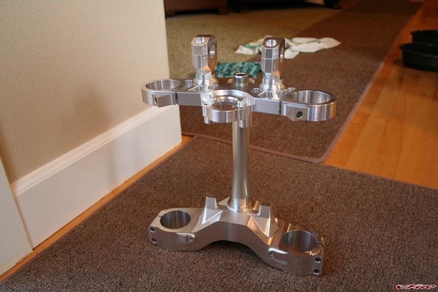
Triple Clamp Assy 072108.jpg
Here's a view of the two different size risers I had made (7mm & 17mm):
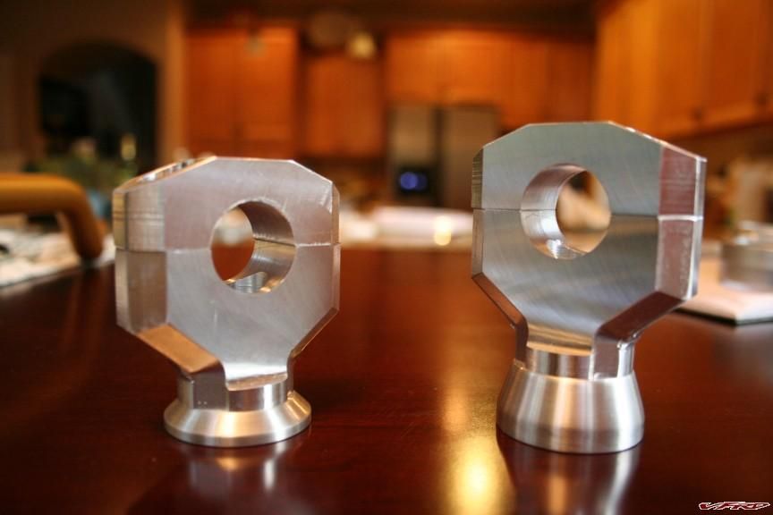
Risers 072108.jpg
The view of the bottom of the bottom clamp (massive):
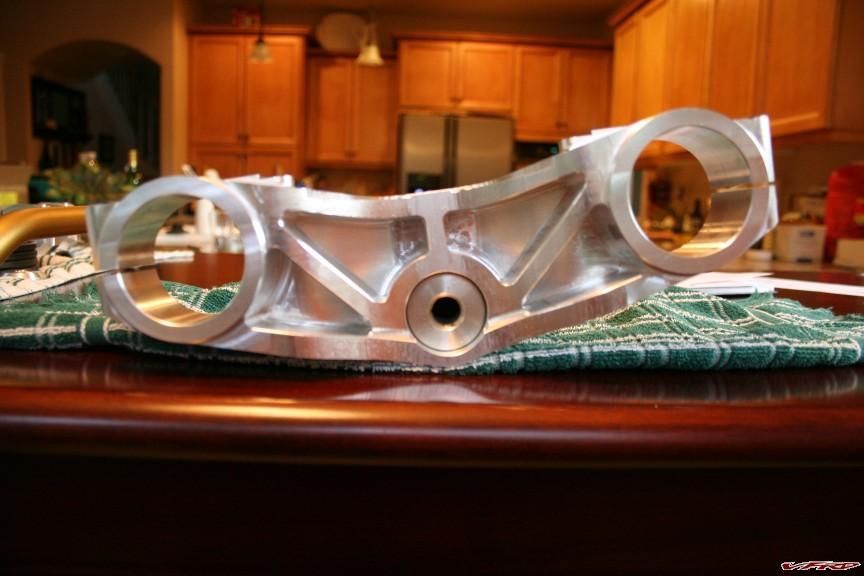
Bottom Triple 072108.jpg
And finally, a view of the bottom of the top clamp:
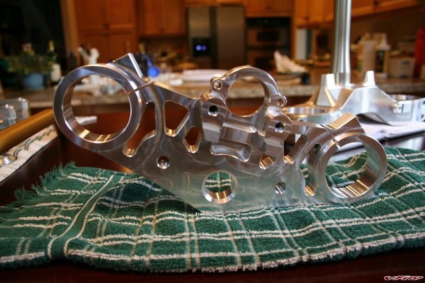
Top Triple 072108.jpg
They're off to the anodizer tomorrow. With any luck I'll have the bike back together for the Kootenay Hootenanny PNWVFRD Meet '08 in August. Woot!!!
-
Oh, and BTW, my 7075 material is in and my machinist says we're cued up to begin this weekend. If all goes well I will post up photos of the finished product early next week! Woot!
-
Spiegler USA offers the LSL superbike kit for VFR's with stock front ends.
-
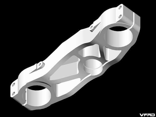
Ok, so I've got the lowers modelled (see below) and I'll meet with my CNC Machinist tonight or tomorrow to discuss the particulars. I'll probably redesign the steering stops and make them a bit more angular (easier to cut?). They still need to beefed up towards the bottom as the stock lower triple is flat and this one is gull-wing in shape based on the stock RC51 lower.
I'll post up when I get estimate on material cost, machine time, and machining costs later this week.
Lower Triple:
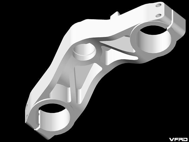
VFR Lower Triple Iso 4.jpeg
VFR Lower Triple Iso 3.jpeg
VFR Lower Triple Iso 2.jpeg
VFR Lower Triple Iso 1.jpeg
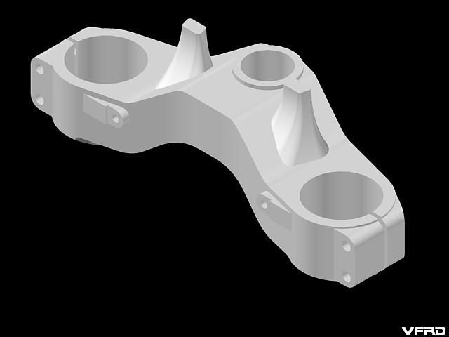
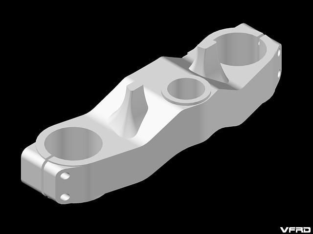
Final Assembly:
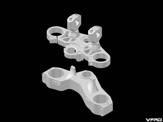
VFR Triple Assembly 1.jpeg
Memorial Stone Placement For Rich Merrill
in USA - Pacific North West
Posted
Good to hear from you Keith. It's really special looking at the picture that V-Fore posted of your garage and daydreaming about the magic of that meet at your place.
I often think about that weekend. It seems so distant sometimes but I remember so many little details and It's been too long since I've been up to see Rich.
I definitely need to make time to visit this summer.
Cheers,
-T