


tok tokkie
-
Posts
201 -
Joined
-
Last visited
Content Type
Forums
Profiles
Gallery
Blogs
Downloads
Events
Everything posted by tok tokkie
-
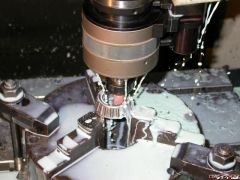
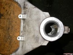
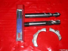
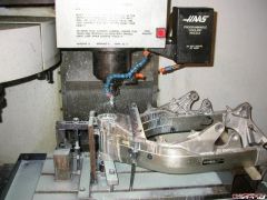
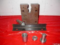
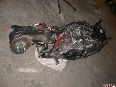
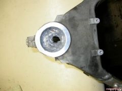
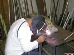
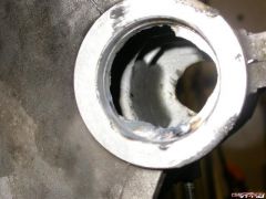
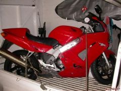
http://www.vfrdiscussion.com/uploads/1130622839/gallery_4545_662_462991.jpg[/img] I wanted to post this under ?Adventures with my VFR? but that is limited to ride reports. It could possibly go in maintenance 'How to Guides' but really it is intended to show what NOT to do and I hope no one else has to do this. I have made my contribution to the statistic of lapsed riders who return to motorcycling and quickly throw the thing down the road. It was a low side and the bike came off far better than me ? 3 cracked ribs & broken collar bone. Rashed plastics with frankenbolt holes popped & indicator pushed through to the inside & rashed muffler; would have been much less if I had a frame slider fitted. Radiator and mirror unbroken. border='0' alt='user posted image' /> Crashed & retrieved When I came to sort out the mess I found that the steering was rattlingly loose. I bought a 2001 with 58 000 km on the clock; new steering head bearings had been fitted at 24 000 when the bike was 2 years old. I was very surprised that the steering was so loose as I had not noticed it before the crash although I had done 1200 kms. I came across this link which advocates torquing the head to 50 ? 60 ft. lbs to properly seat the bearings. When I did this I heard 2 sharp cracks almost like bearing balls cracking but thought it was the sticktion as the bearing races settled properly against the seats, just as the article said they would. But things were obviously not right so I had to strip the front end off & see what was going on. When I got the steering stem out I found that the cracking noise was the cast in collar against which the lower bearing seats being broken off. I felt sick, sort of faint. From a relatively mildly damaged bike I had progressed it to being truly hugely damaged. Slept on the problem and decided to weld it up. This is going to be my final bike, I have no intention of selling it; will give it to my son when I am done with it. There is no way that I could sell a bike with a welded steering head to someone else but I am willing to ride it as I am confident in the repairs. I have a tig welder but have never done aluminium tig welding. Next to me at work is a API(?) certified welder who has worked on oil rigs in the Persian Gulf and been an instructor at a local welding school ? I would get Ridwaan to do the welding. I have a cnc machining centre. A machining centre is like a milling machine but they are called machining centres for some reason ? there are horizontal or vertical ones. I have a Haas VF2 vmc made in California. So between the two machines I have and with Ridwaan?s help I should be able to fix this thing. I stripped the frame off the bike; not too difficult as there was not much more that I needed to take off since the fairing was at the spray painter & the front end was out. Just take the tank right off and the tail section and loosen the wiring harness & the frame lifts off the remainder. border='0' alt='user posted image' /> no frame 3.jpg Frame stripped off. Remains resting on sandbag Ridwaan welded it up although it was quite difficult working within the confined space of the steering head. I then put the frame on the table of the Haas and sorted out how I was going to clamp it there while machining it. The vital thing is to machine the repaired lower bearing seat dead in line with the upper bearing seat. I made a steel disk that just fitted inside the upper bearing seat which I bolted to the table of the Haas and centered the spindle on it. Then I fitted the frame upside down onto that disk so the welded part was uppermost. I made another disk that just fitted the undamaged step where the dust seal fits under the lower bearing, this had a long 32mm tail that I fitted into a chuck so that it could slide up and down. I was then able to fit this into the spindle of the Haas and lower it into the steering head with the spindle accurately above the disk bolted to the table so the steering head was exactly where it needed to be. I sorted out how to clamp it in this position. border='0' alt='user posted image' /> tig 1.jpg border='0' alt='user posted image' /> welded 1.jpg Welded I machined away the excess material using a new 4-flute HSS (high speed steel) end mill. It clearly was not cutting well ? you can hear when things are cutting well or poorly. The rods that Ridwaan had used are really tough aluminium. When I had a look ? you can?t see what is going on while cutting as everything is showered in cutting oil ? I saw that this really was not the right tool as the aluminium was smeared and the job had shifted towards the back of the Haas as the clamping was not good enough. I had now overcut on the one side so Ridwaan had to fix that up again. The tool was badly worn. border='0' alt='user posted image' /> machine 1.jpg border='0' alt='user posted image' /> machinig fixture 3.jpg The fixture to secure the steering head front to back in the Haas. The two disks that fit into the steering head for aligning it in the Haas. The tool for tightening the bearing nuts. The tool for driving the lower bearing onto the steering stem. I went to Keith, who supplies me with cutters, and asked for the best cutter for aluminium. He sold me a Korean made YG Alupower tungsten carbide cutter. Normally hss tools have a sharper edge than tc but these tools are specially designed for aluminium by having a different geometry to the cutting edge. To better secure the job front to back in the Haas I machined a slot in a heavy steel plate that just fitted over the lugs at the front of the steering head (onto which the frame for the instruments is bolted). This I welded to a piece of angle iron which I bolted to the table. Now I had the frame properly anchored front to back & side to side. border='0' alt='user posted image' /> cutters.jpg Cutter at back is Alupower. Front cutter is badly worn end mill. Two pieces that broke out of the steering head. When I now machined it you could hear how sweetly the new cutter was working. On a cnc machine you simply specify the center and radius of a circle you want to cut & the tool orbits around the center point. You can cut to bearing tolerances. The OD of the lower bearing is 55mm but I was using a 12mm cutter to machine this. On the control panel of the machine you can set the off-set for the tool from the defined path. For a bearing you leave 0,5mm to start with then use light finishing cuts to the final size. The off-set can be set to 0.001 mm (1 micron, or more correctly 1 micrometer = 0.00004 inches) but the machine resolves to 0.003mm. All of this is swamped by tool deflection which is why you need to do the final light cuts, measuring after each. I machined it to size & tapped the bearing race in. border='0' alt='user posted image' /> bearing in 2.jpg I chose to convert to taperd roller bearings. The lower bearing is a standard #320006 bearing but the upper bearing is non-standard. There is no AllBalls here that I can get the required bearing which has a 26mm bore. The closest is #32005 which has a 25mm bore. I got one of these & ground the bore to 26mm on my Haas. I have a 5x spindle speeder into which I fitted a little mounted point grindstone which I spun at 20 000 rpm (speeder maximum). Taking 0.02 off-set increments I ground it to 26mm. You want to have a lot of cutting oil when grinding as the dust must not get into the slideways of the machine. I am very reluctant to ever grind in my Haas. border='0' alt='user posted image' /> grind bearing 2.jpg Grinding the upper bearing to size.
-
From the album: One
-
From the album: One
-
From the album: One
-
From the album: One
-
From the album: One
-
From the album: One
-
From the album: One
-
From the album: One
-
From the album: One
-
From the album: One
-
There are three problems with getting stuff sent in: 1. Customs duty. I once brought in a load of CD's direct from Rhino. The duties ended up at THREE times the cost of the CD's. At that stage you simply have to pay. 2. Theft in our post office. A national scandel a while ago but much improved over the last few years. 3. Paying for the things. I ordered a pair of binoculars from a US site about 4 months ago & they said my credit card would not work. The big places like Amazon have no problem with it but smaller places seem to have difficulty. So I hope to get my binoculars this month through a person comming to Cape Town on a visit. Huge advantage as he has the binoculars as part of his stuff so no customs duty problem. Any VFRD members comming to Cape Town let me know. Can use my bike (when it's fixed as I dropped it last month). I particularly would like to do BLS 'titanium butt' mod. You guys really have something in EBay that I envy. Finally, I like to make things myself. I have a cnc mill so could easily make the spider wheel myself; it is just a matter of time & priorities.
-
The bore of the Factory Pro star wheel looks much smaller than the stockie in your photo. Must be an optical illusion since it all fitted together no problem. What is to prevent you from simply replacing the plain wheel on the stock arm with a ball bearing? I appreciate that you will not have the revised star wheel profile & slightly stiffer spring. Factory Pro is unlikely to be available to me here.
-
Me too; same as for Swiffer's fairing copy process.
-
Me too. Images are all missing, were they from before the Great Crash?
-
 The shot looking down the valley with the road twisting & twisting & twisting down really impresses the size of your mountains on me. Awesome.