bsujanto
-
Posts
48 -
Joined
-
Last visited
bsujanto's Achievements
")


-
Did you do it on Compression Gold Valve or Rebound Gold Valve? I had no issue to do it on Compression Gold Valve. Anyway I had a reply from Race Tech. "In this situation we drill the hole at a slight angle, so if you drill it on one of the ports on the bottom of the oring slot you should have enough material there to drill it."
-
Not decide it yet, but thinking of it :biggrin:
-
The Ohlins has 1092-69 spring which is 170 N/mm = 17.3 kg/mm. Without special request, this rate should come stock for Ohlins HO 605 A little story when I ordered this Ohlins. At the beginning, this Ohlins came with -64 = 160 N as I requested it after consulting with Ohlins USA. They said it is suiable for 140-155 lbs rider weight. I found out that it felt soft. It needed a lot of compression damping to settle it. Well, obviously it was undersprung with 160 N. I should have left it stock from Ohlins. Finally, I bought a 170 spring and install it myself. The Ohlins is up by 13% compared to stock shock spring. If the maintaining balance theory is right, I should go +13% at front which is 0.83 --> 0.85 spring. That would be something to consider. The oil level is 10 cm now.
-
Race Tech manual says if your bike does not have any external rebound adjusters (on fork cap) you will need to drill a small bleed into one of the three round ports between the valve stack and Teflon band of Rebound Gold Valve using 1.3 mm diameter drill bit. This rule is applied to VFR, but the space between valve stack and Teflon band is 1.5 mm. If I make the bleed hole right beside the Teflon band, there is only 0.2 mm left at the port wall for the valve to stick to. That's obviously too risky and I decided not to drill it and just installed it. Any idea what I should expect without this bleed hole?
-
racetech calculation gives me .94. I'm just afraid that my bike becomes harsh with this higher rate spring. So far I feel it's ok and quite in rhythm with Ohlins at the back.
-
Only 147 (67kg). I guess stock spring is ok for me
-
Anyone knows the stock fork spring rate for 2002+ VFR? Is it similar to 98-02 VFR at 0.74 kg/mm? I'm moving rebound gold valve from CBR600 to my VTEC. It needs the spring rate to recalculate the valve stack.
-
I agree with you it's pretty lean. I also wonder if it's a wild number, but considering that on 40% it gets steadily leaner from 6000 and up. So I guess this 17.3 at 8750 is not that wild, is it. From the left side of the bike, I use the more accessible O2 bung. It's the one with plate protector. I guess it's coming from Front left and rear right cylinder. Sorry I always forget cylinder numbering on VFR. Which one d' you use for your autotune?
-
Yes, I did. I plugged the supply hose at the air box. What makes think of that?
-
It uses different connectors. Obviously it's not plug and play.
-
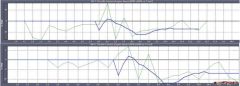
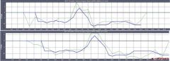
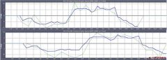
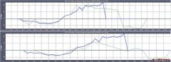
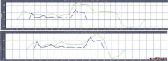
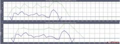
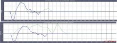
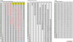
Here I have some interesting comparison between my custom map and map provided by Power Commander for US and Euro bike stock exhaust stock air filter, shown on PC III software. Bold blue line is the custom map. Top picture at each TP is comparison with US bike. Bottom with Euro bike. At 2% TP At 5% TP At 10% TP At 20% TP At 40% TP At 60% TP At 80% TP At 100% TP In many cases, the curve of the custom map looks similar to PC provided map, only that custom map is down shifted. PC provided map is more aggressive in richening the AFR. It's quite in line with the quote from my DynoJet source. The humidity here is 70-90% all day. The higher the humidity, the less oxygen available, the less gasoline needed to reach target AFR. PC provided maps are designed for less humid country and it is too rich for my use. The custom map somehow proves it right.
-
AFR Before n After PC Custom Map
Images added to a gallery album owned by bsujanto in Member's Gallery
AFR Before n After PC Custom Map -
-
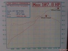
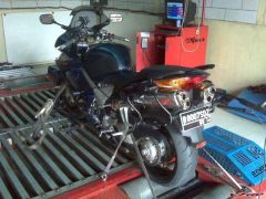
A picture when it's on dyno Why not get this besides AFR
-
Yes, it is. Thanks. I worked out my custom map calculation based on the table as target AFR and the cumulative actual AFR from dyno session and street riding. Dyno session takes care of high rpm and high tp area, while street riding takes care of low n med rpm at low tp. Before being taken to calculation sheet, I put all actual AFR data at each TP steps on graphics so I could see and delete any irregular datas. This irregular datas are represented by dots or spikes that are clearly outside the main stream of data. Anyway, I got the custom map uploaded into PC III and had the AFR logged afterward on the street. I didn't get feedback for all cells though, but we can see AFR is improved towards the target at many cells. I will keep doing this everytime I ride and get more and more valid datas to adjust the custom map further. Regarding the bike itself, I feel it is significantly smoother at "parking lot" speed and the vtec transition has also improved. I haven't got a chance to measure the gas mileage, but the custom map indicates that it could be worse now.
-
I did the test just now. It's on centre stand. I forgot what gear it's in, but it's on 5%TP, 4.7K RPM, around 80km/h indicated speed. Starting from 74 - 111 deg C, I can say that AFR is flickering around 13.6-13.8, constantly along the temp range. Above 105 deg C, I reckon that 13.5 and 13.6 showed up in a blink or two, but I think we can omit it. Though the theory that ECU dumps more fuel at high temp is not proven at this test, we should remember that it is done only at 5%TP. I think it's not conclusive enough.