

yogisays09
-
Posts
30 -
Joined
-
Last visited
Content Type
Forums
Profiles
Gallery
Blogs
Downloads
Events
Posts posted by yogisays09
-
-
On 8/12/2018 at 10:24 PM, rhoderage said:
Any thoughts on whether this will work with a SpeedoDRD inline? (If I understand things correctly, these both plug into the same port... can they be piggy-backed?)
If so, any particular order they should be installed?
I am -1+2 geared so I don't want to give up the speedo correction, but a gear indicator thats plug and play would be a good addition IMHO
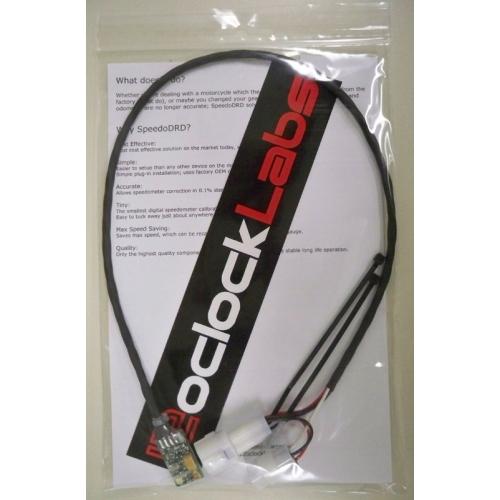
yes you can install both together, you will have to follow the Healtechs X type installation instructions.
https://www.healtech-electronics.com/docs/GPXT_UsersGuide_en.pdf
On 8/20/2018 at 12:59 AM, JAlves said:Hi, I'm looking for something like this, where did you connect it?
Do you have the instructions?
Thank you
Download the healtech X type gear indicator manual. it has all the installation information need
https://www.healtech-electronics.com/docs/GPXT_UsersGuide_en.pdf
-
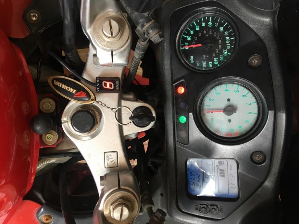
Installed and it works great
.thumb.JPG.91bf86b2966c90b3b068fb2209520905.JPG)
-
 2
2
-
 1
1
-
-
On 7/22/2018 at 8:54 PM, MadScientist said:
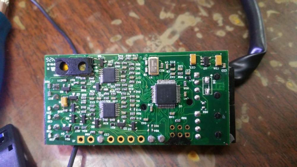
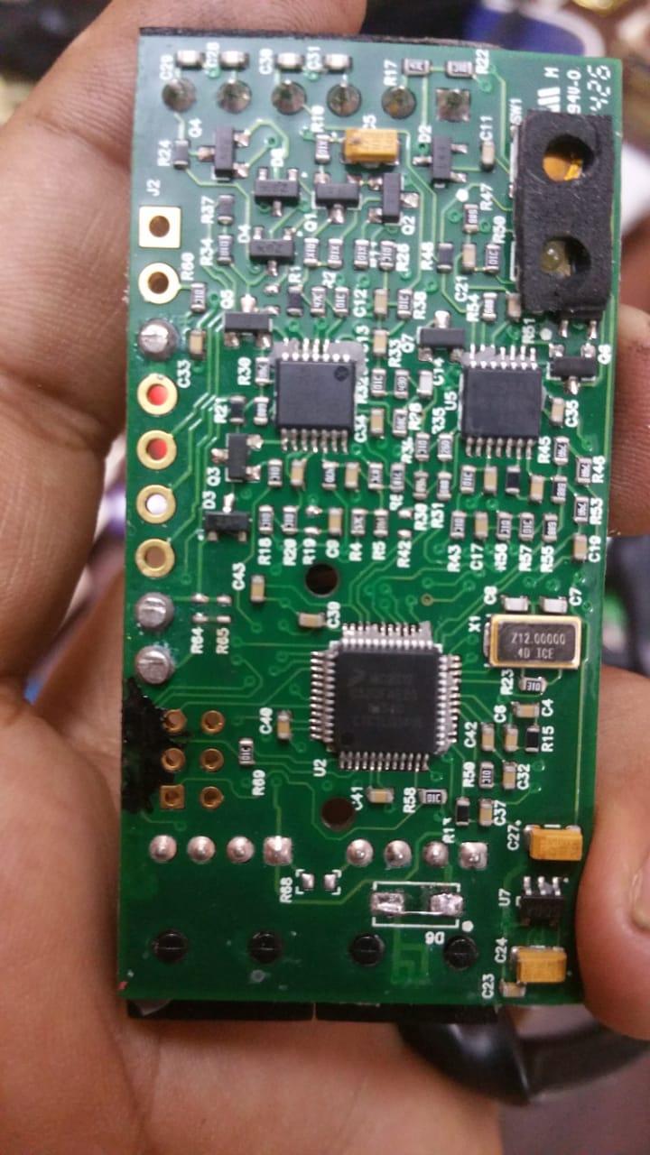
I just noticed R19 is missing from the bottom(?) side of the board, there may not have been a resistor installed at that position though. Check out the solder pads for evidence of broken solder and maybe check in the potting material to see if it got stuck upon removal. R64, R65, and R68 appear to have virgin solder pads, so I think they were not installed. This is somewhat common, I would bet they are populated on different versions of the board.
I assume you know a diode allows directional control of current flow. You may have to try both orientations when you replace it, unless you were able to determine the direction of the original diode.
Thanks for the pictures!
Nothing is missing on R19, it was blank. Pads are virgin on all the blank plots.
Yes i learnt what a diode it and before removing the old ones i noted down the direction in which it was placed.
I have tried and tested the module several times and on 2 different bikes as well, it doesn't work. Have no other choice and have to throw this unit. Without the circuit diagram it is not possibel to proceed.
-
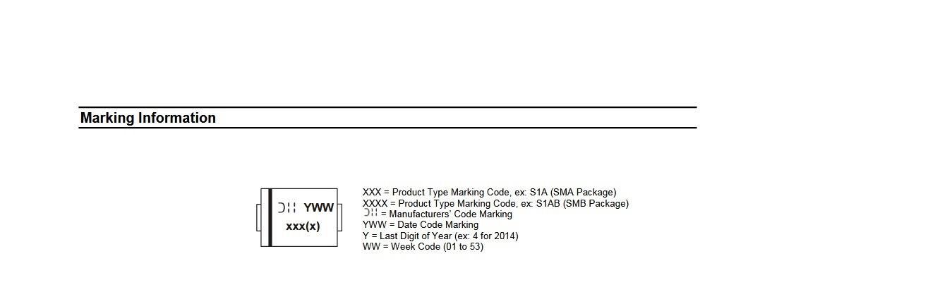
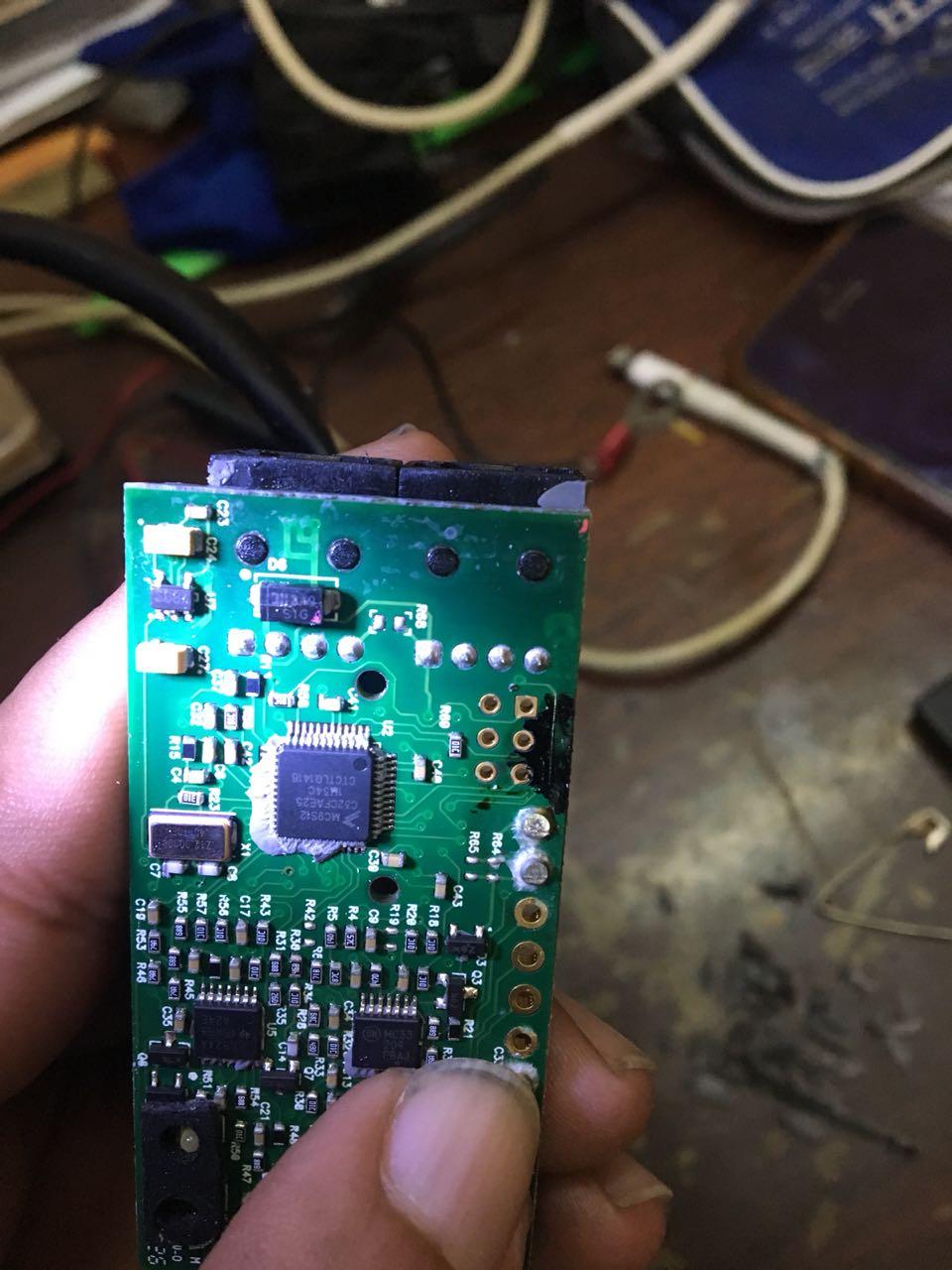
Finally decoded the Diode 🤗
]:: 349 = Made in 49th Week of 2013
S1G is the type of the diode.

-
1
-
-
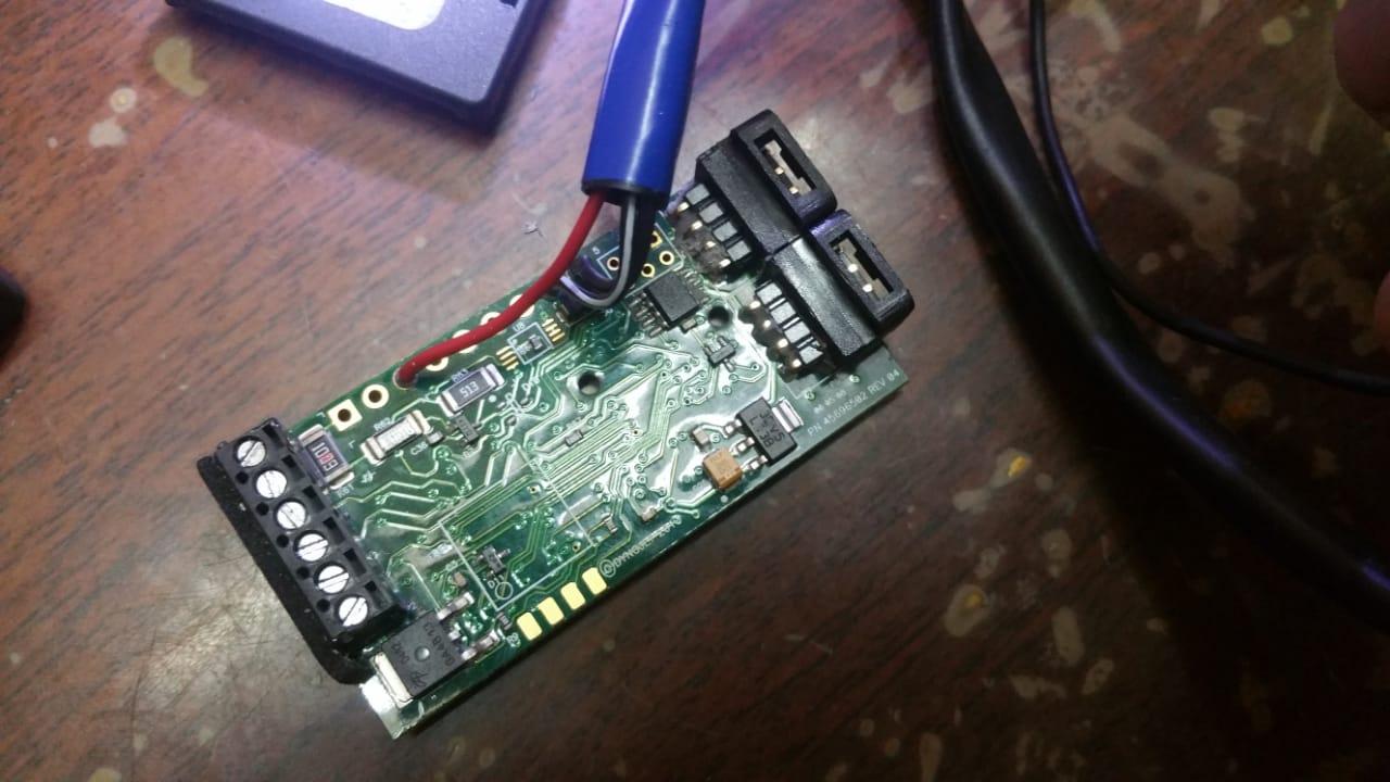
Looking at this pic i can see 4 legs (4 golden pads) which can be the connectors to connect this module to the computer using USB2 but not sure.
-
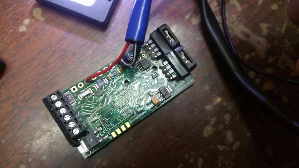
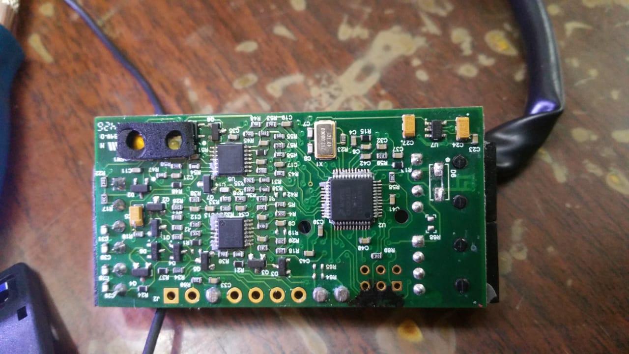
On 7/13/2018 at 2:19 AM, MadScientist said:
I wouldn't mind some more detailed pictures of the front and back of the board, if possible.
Here you go , some more pics of the module. Removed the unit from the bike and will search for a S1G diode rectifier and retry. Meanwhile no positive reply from Dynojet. They wont share the circuit diagram I am sure.
.thumb.jpeg.f3b05cd1cdfd2e2f96a412279ceb20a7.jpeg)

.thumb.jpeg.ec3afc324cf89825c1e75f75802c73c9.jpeg)

-
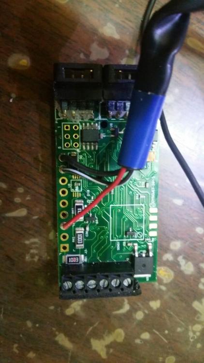
Thanks a ton MadScientist for the reply . I used this method to remove the old diode " The other method I use is to melt a tiny amount of solder onto the pads, place the component on top and hold it in place as I re-melt the solder on the pads. " and jumped the pads with a wire.
UNFORTUNATELY the unit is not functioning as it should, its flashing green light and AFR reads as 9.99. My CBR1000 also has an Autotune which flashes red light upon start up and not green.
I have emailed DJ again with another name and email just to see what they reply.
By the way i am installing this on my 2011 GSF1250 bandit.
-
Success at step 1 achieved. there i a similar diode on the back side of the board and upon checking the continuity on the meter it as a direct 1:1 connection and following laymans proceedure i removed the busted diode from the board and jumped the 2 points with a very thin wire element and to my surprise the unit came back to life on bench testing. Will be installing it to on the bike and do a live test.
-
1
-
-
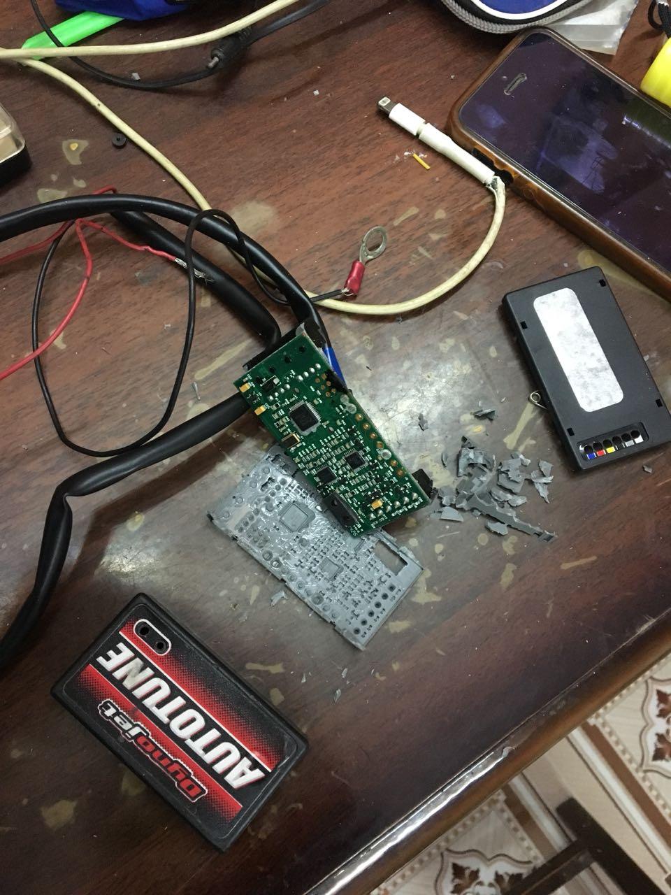
Dear tech Gurus
I bought an used Autotune module but the unit never turned on. out of curiosity i disassembled the entire unit and this is what i found on the board. I tried to contact DJ but they were unable to help. my google skills explains me that the burnt component is a diode.
Currently I tried t power the unit with a 9V adapter (9.62V on multimeter) and tested the output at the burnt diode which was 2.64Volts. I gave direct 9.6V to the output side of the diode still the unit did not turn up.
techies pls help to bring my autotune back to life.

.thumb.jpeg.a370d3532bf732109ec4c8a8cf3d949b.jpeg)

-
1
-
-
3 hours ago, JZH said:
Anyone know which Denso pn. the VFR1200 uses?
Ciao,
Denso part number means like this ? 129700-5370
-
Here is the link for the gear indicator for the 5th Gen.
Looks like replica of the Healtech X Type , so the wiring would be the same , the male female plugs in tho speedo sensor which is on the sprocket cover. and the single wire green one taken signal from the ECM RPM wire. which is A18 yellow wire with green trace.
-
1
-
-
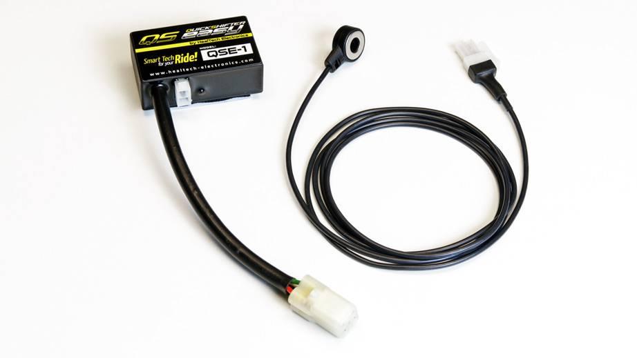
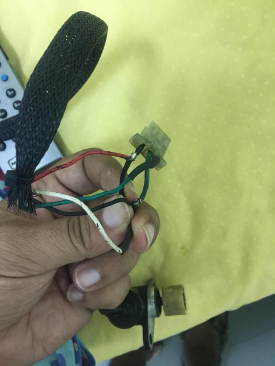
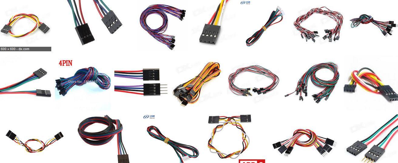
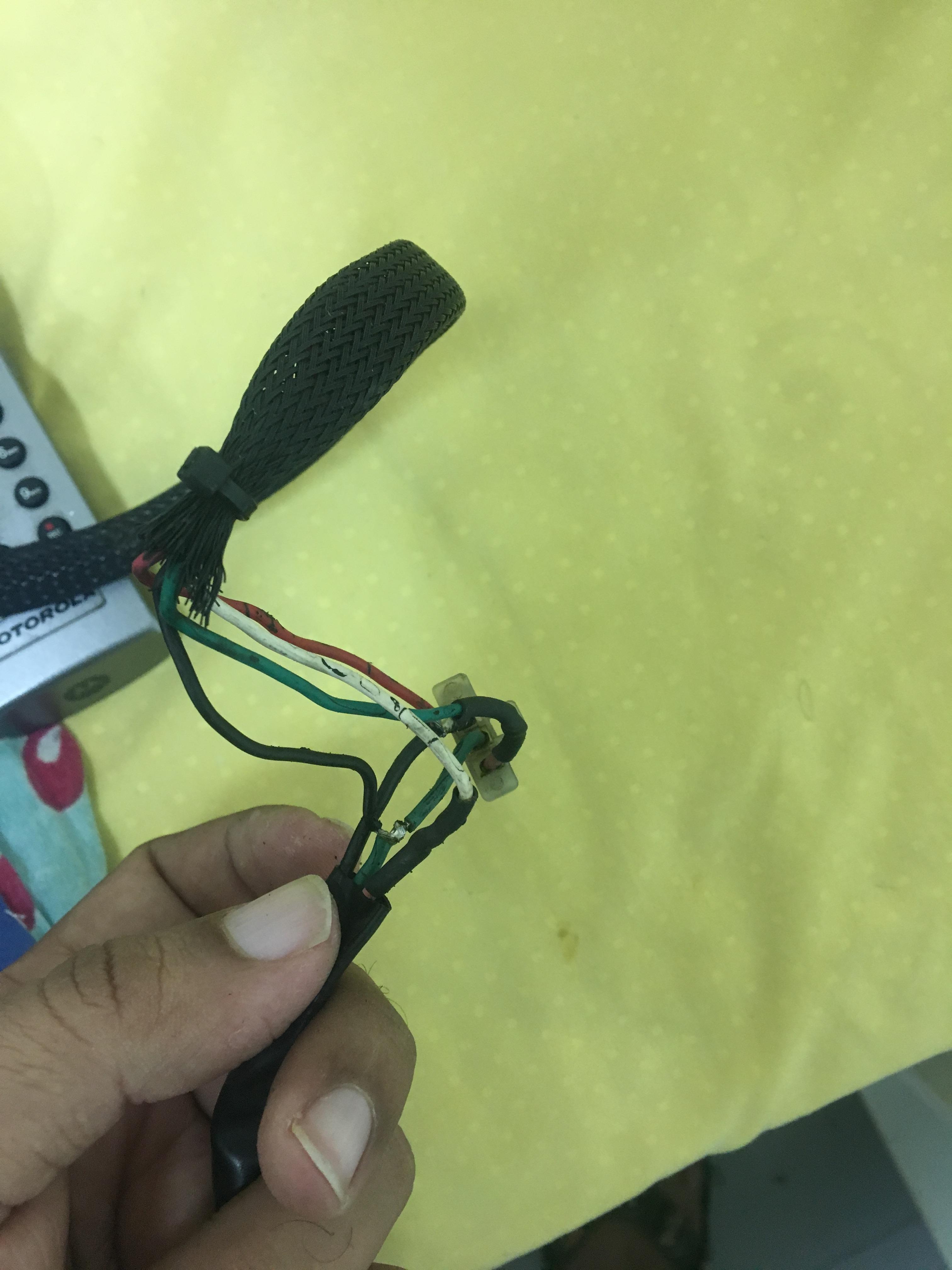
Hello People,
I was searching for a cheap quickshifter to add to my CBR which runs a power commander 5. During the search found that healtech sells the IQSE sensor separately for $50ish. I bought it thinking that it would work like a normal push or pull type quickshift which closes the circuit inside the sensor upon upshift or downshift action of the gear lever.
But this Healtech ring sensor seems to be some kind of Strain gauge or stress gauge and not an open circuit managed sensor. In short it was useless for me and the Power commander needs a circuit operated sensor.
Does anybody know how this ring sensor works? and if there a way i can get this working with the PC5, its a 2 wire sensor.
I have attached a photo of the unit, I have just got the sensor harness only and not the unit.
-
Hey John, if you find these connectors pls do share with us, I check with manufacturers of Alibaba as well and no one could identify these.
-
3 hours ago, JZH said:
Thanks, Yogi. I'm still going to try to find the same locking connector that DynoJet used, but if I can't find it I will use the computer connector.
Cheers,
Most welcome John, i tried a lot to find this connector online as well as with Chinese manufacturers of sockets. but could not find it. Probably made to order for Dynojet by manufacturer.
it is very difficult to find these things India as well and the prices are like you can buy 100 pcs computer 4 wire thingy for the price of 1 link cable at the dynojet.
-
Use 4 pin/wire female dupont cable of the computer. This CAN termination plug has a 180-220 Ohms resistor running accross the first and the last pin. if you wish to make your own plug , use the 4 pin dupont and remove the middle 2 wires from the socket and solder and 180-220 ohms resistor accross the first and last pin.
If you just want a link cable use the 4 wire female - female dupont , its direct snug fit. Using the same on my 07 1000RR

-
9 hours ago, JZH said:
Yes, but the pre-made Triumph lead costs less than $10 online!
Ciao,
Wow i just checked this triumph T2500676 , this is a plug and play OEM thing. Thanks John
-
-
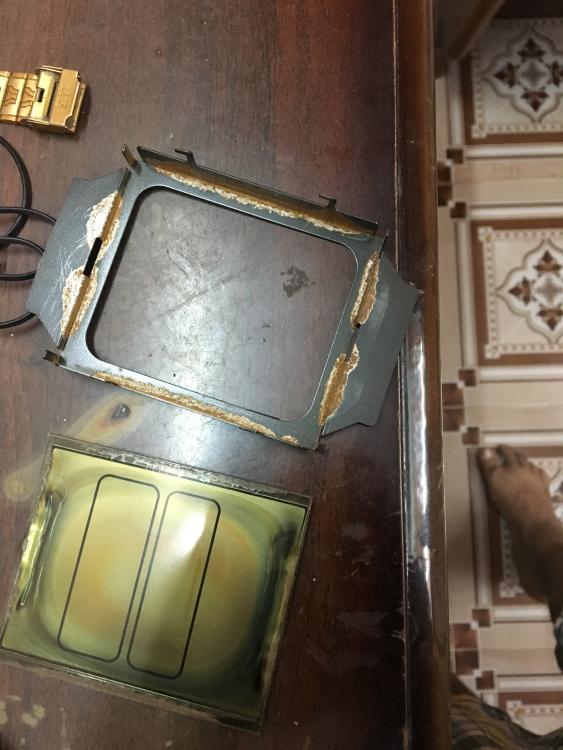
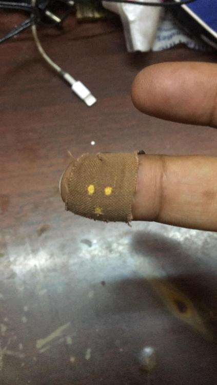
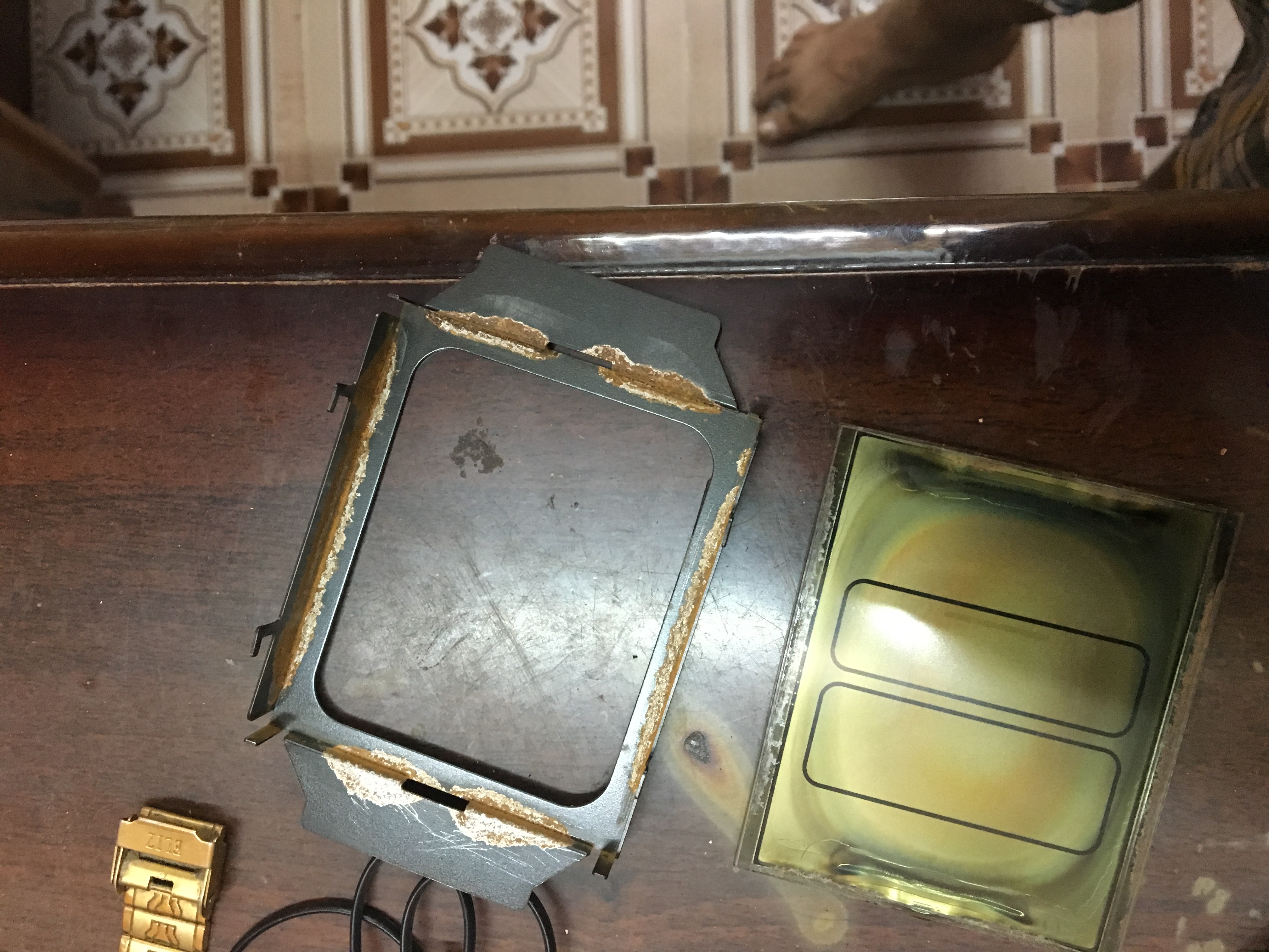
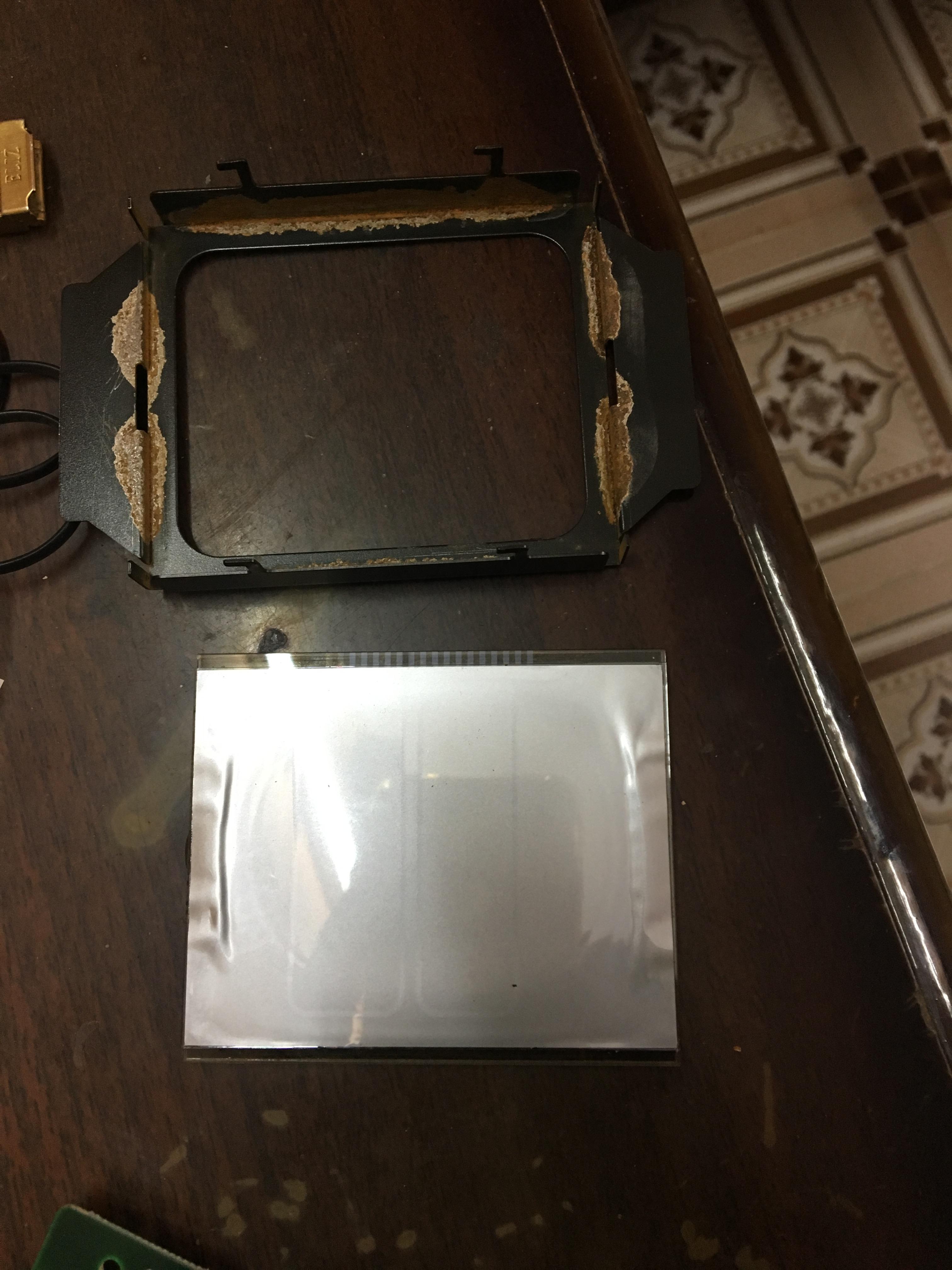
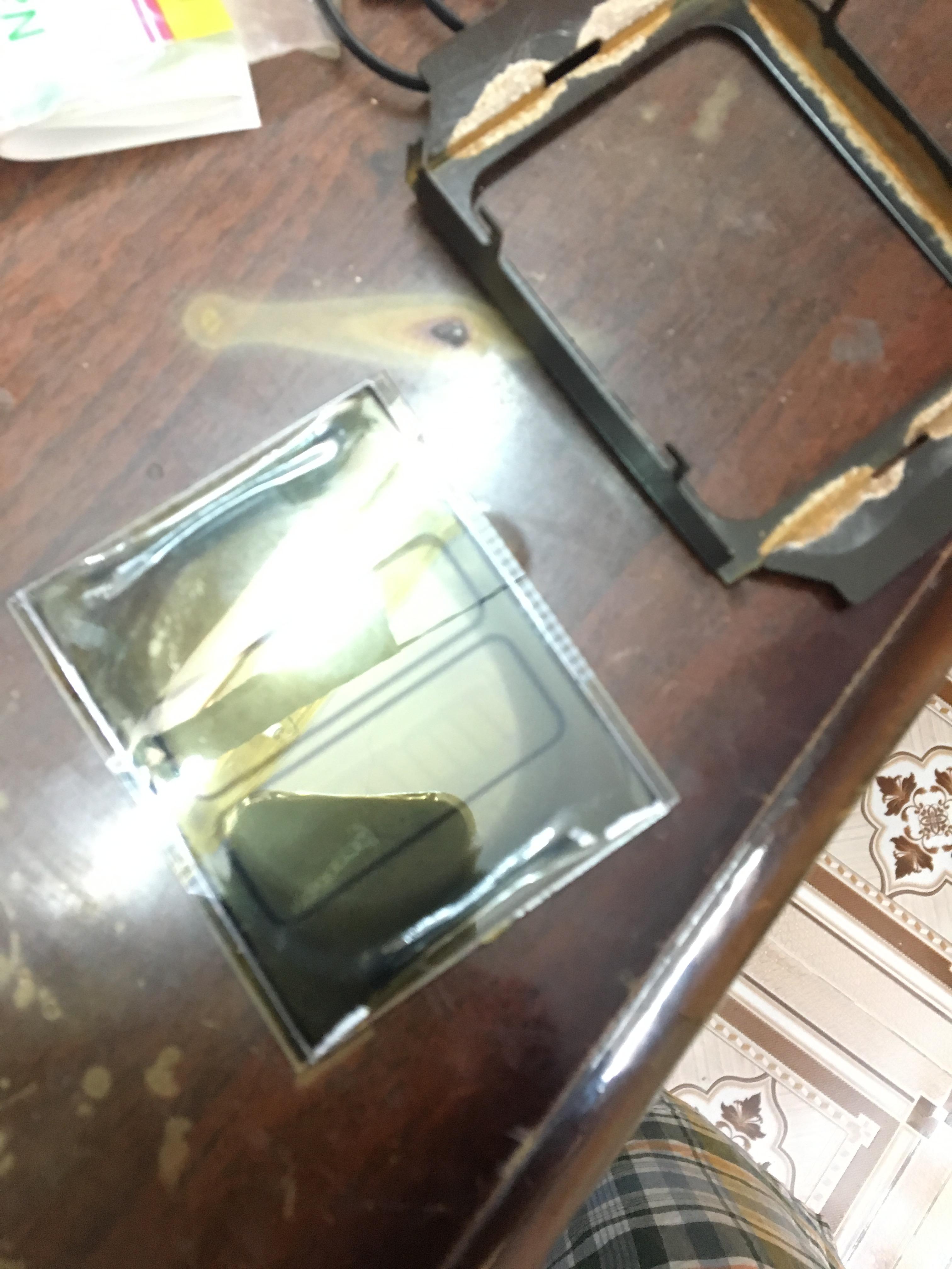
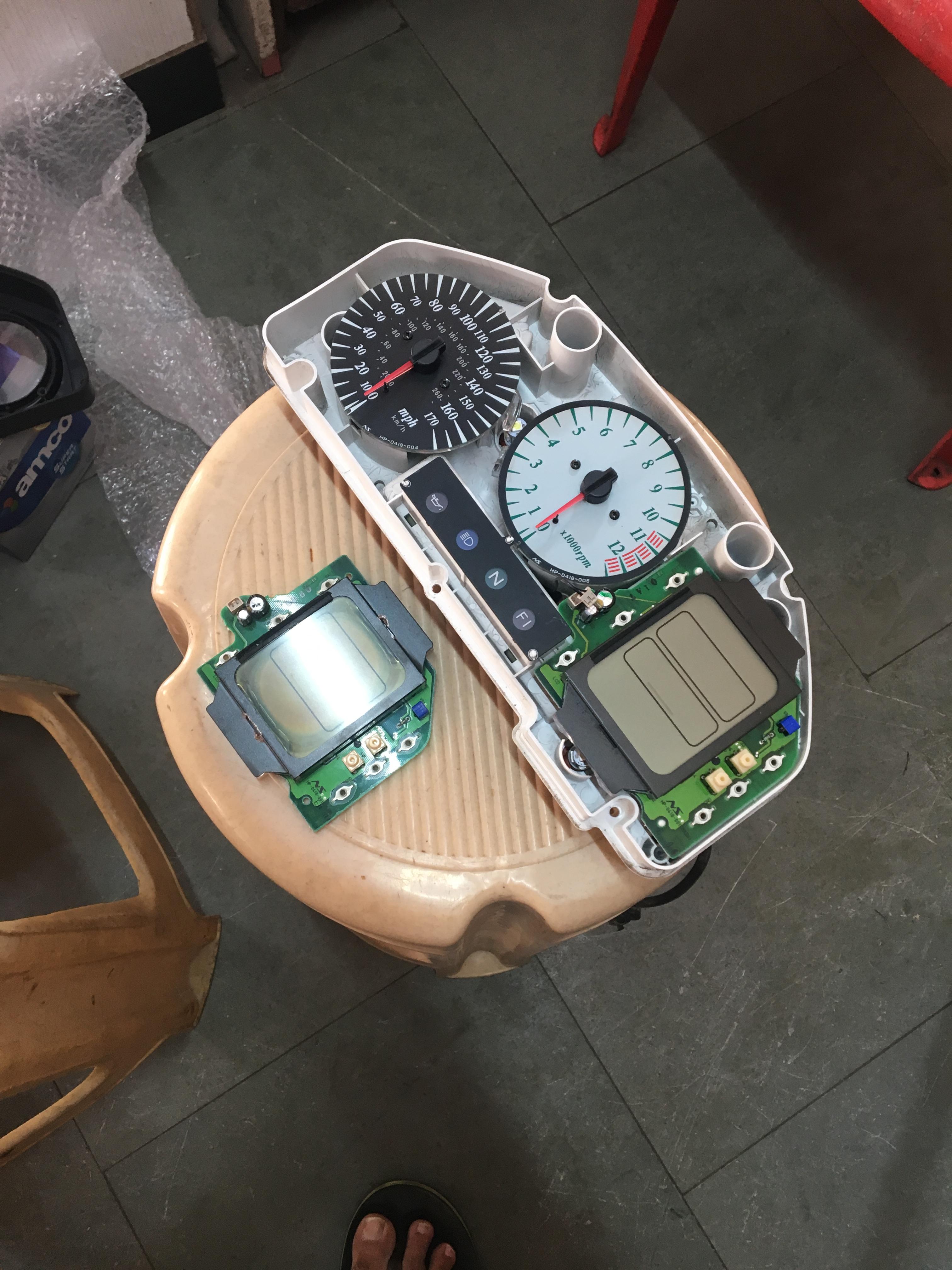
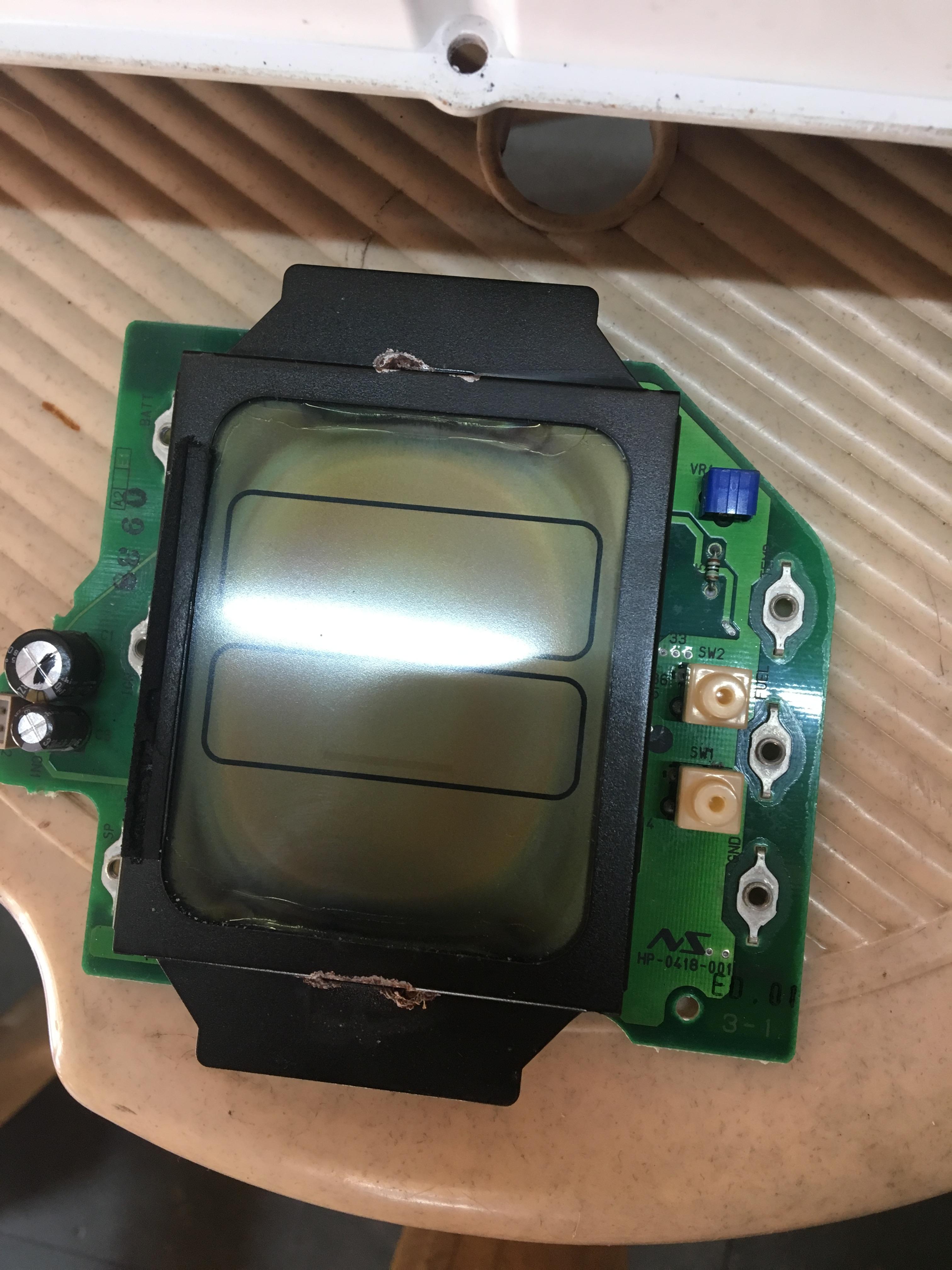
Did some DiY on the old LCD unit. Seems like water damage. The glass of the lcd is very sharp at the edge and it deep cut my finger.
the bottom polarization film is busted and i am planning to use film from a samsung phone. Lets see how it works. I was expecting the top film to be bad but that was absolutely fine.


-
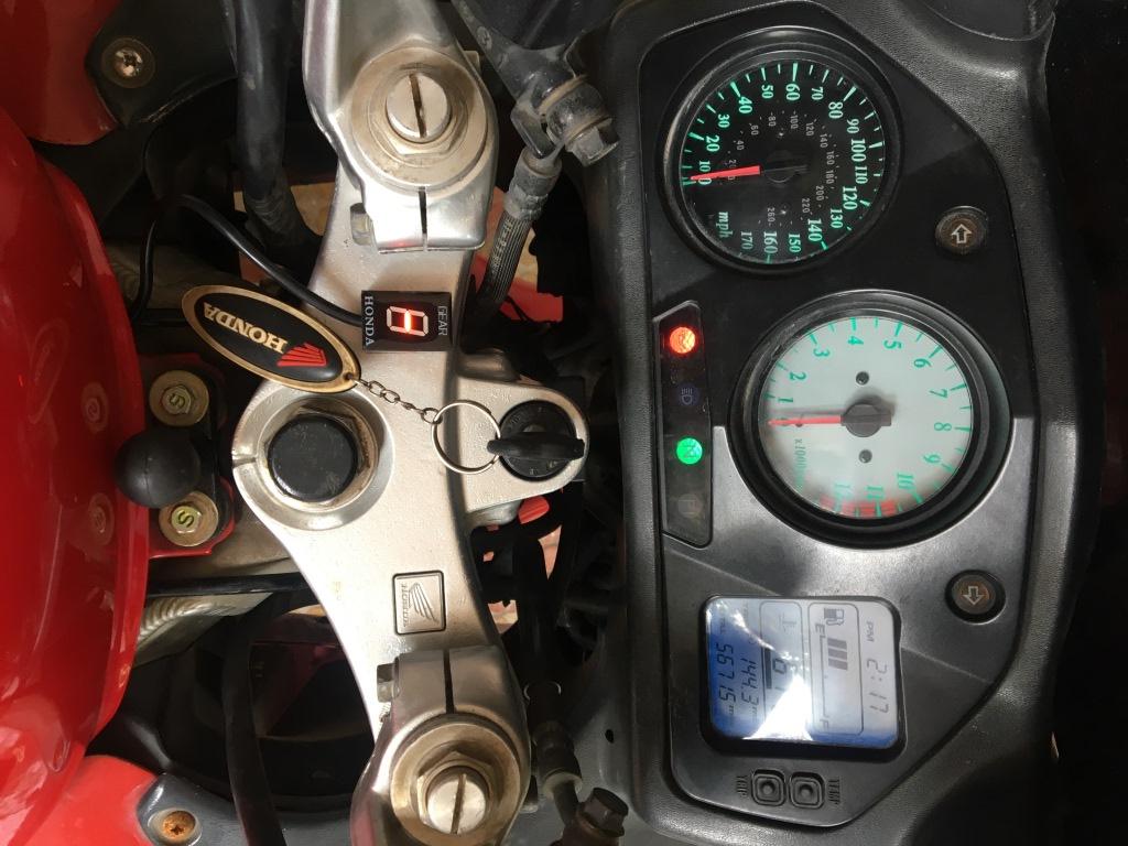
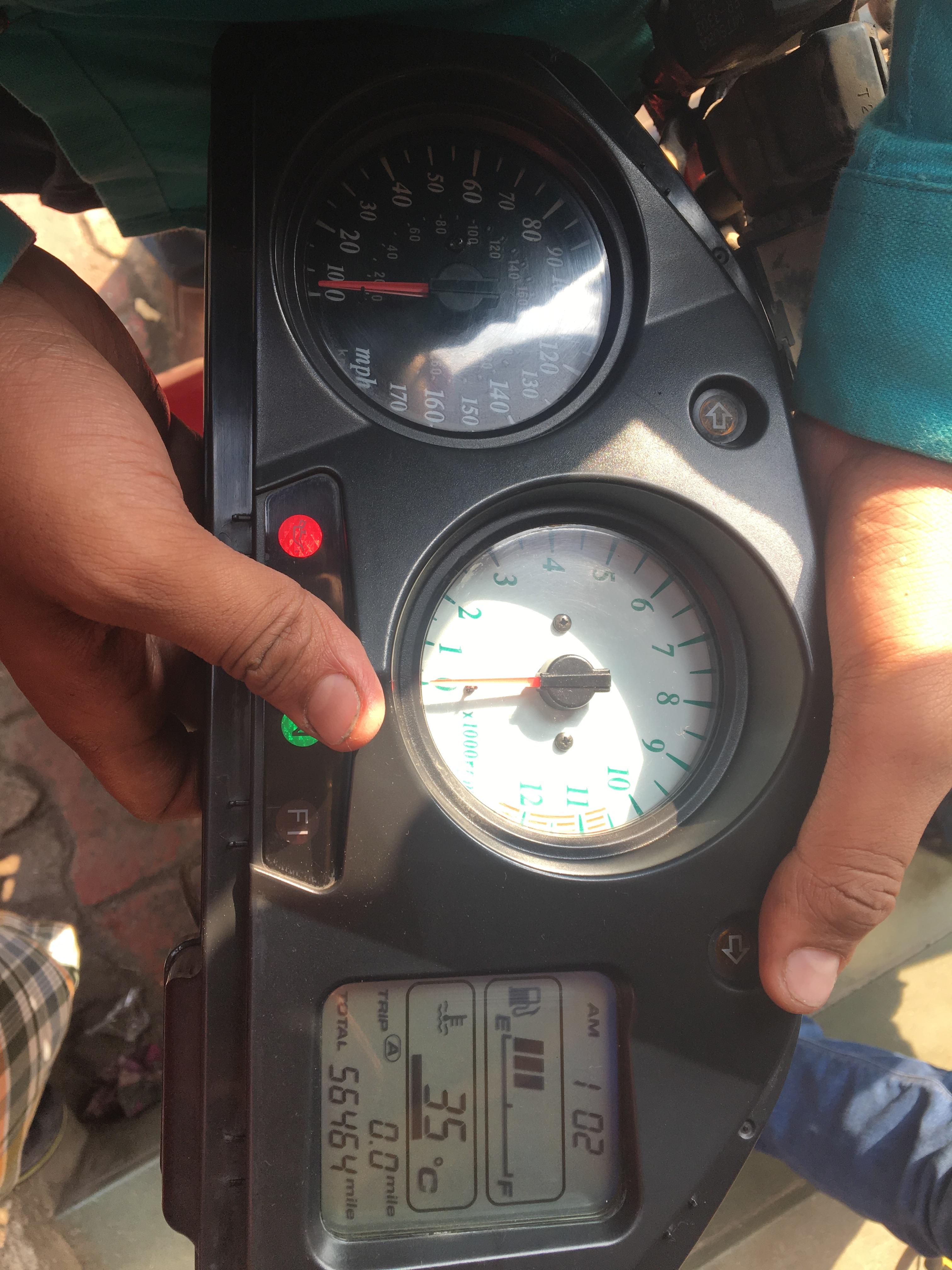
22 hours ago, JZH said:
Looks like your bike gained some miles! But I'm glad it worked.
Ciao,
Hahaha yes , it did gain a few miles but for good. Odo reading does not really matter here in India
-
Thanks a lot John. Speedo sorted for life.


-
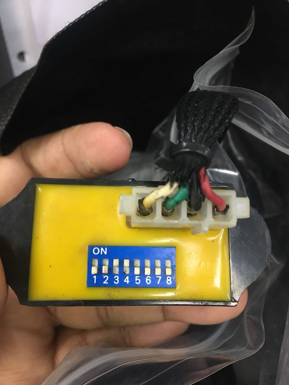
Okay gents, after a lot of scratching google b@lls , found out what this thing is. its a speedo calibrator from Yellr. This device is called the Yellow Box V3
-
On 1/9/2018 at 3:48 PM, Mohawk said:
Speedo adjuster = Yes, BUT is it an accurisor as in speedo healer ? or a Fixer as in designed to fool the ECU about bike speed to beeat the JDM 180K limit ?
On 1/9/2018 at 7:19 PM, JZH said:Possibly the latter, but why would they need DIP switches to do that?
(The LCD is on its way, Yogi.)
Ciao,
Thanks a lot John for the LCD, really appreciate your help.
To clear the confusion the speedo sensor thing, last time my VFR threw an error code for the speed sensor after which i cleaned it and reinstalled. Worked fine there after but i ordered a used sensor for bad times and the used one came with this adapter kind of thing. I did not knew what this extra attachment was until i received the sensor today.
Here is the clear pic of the adapter and I still dont have any idea what this thing is. Can you pls help identifying what this thing is.
There are no stickers nothing no brand name on this black box.


-
These immobilizer keys are very cheap if you get the ID46 transponders separately and blanks keys separate. 10pcs chips n 10pcs keys shouldnot cost more than $20.
And programming is free as you do it urself.
Thanks to the chinese at our help these bits cost peanuts.
-
On 1/9/2018 at 7:19 PM, JZH said:
Possibly the latter, but why would they need DIP switches to do that?
(The LCD is on its way, Yogi.)
Ciao,
Dear John,
I have sent you a PM , can you pls help on that.
.JPG.9ff6a3fb28e3dee1d60085236dd3f475.JPG)

.jpeg.a36b253c98005a4c81648a0ef0e40670.jpeg)
.jpeg.d50a015a31a4b953ba80aa7f98ca4407.jpeg)

.jpeg.5ef2b9859505d1f02d087b1e65ad0f77.jpeg)


Cheaper gear indicator option for the VFR800
in Fifth Generation VFR's
Posted
Yes looks like its not mentioned in there, but i fairly remember ready in some instructions where you can run both of them together.
to me this is how the wiring will need to be done , have a look the hand made diagram. Ignore the bad hand writing please.